

Tinytag Ultra 2 TGU-4550 User Manual
…………………………………………………………………………….
inytag Ultra 2
Tinytag Ultra 2
T
Tinytag Ultra 2 Tinytag Ultra 2
Thermocouple Manual
Thermocouple Manual
Thermocouple ManualThermocouple Manual
TGU
TGU----4550
TGUTGU
4550
45504550
Warnings
Warnings
WarningsWarnings
• This logger must be used in accordance with the information provided in this
manual.
• This equipment contains a lithium battery. Do not cut open, incinerate,
recharge or expose to temperatures in excess of 100°C (212°F). Danger of
explosion if the battery is incorrectly fitted.
• The battery should only be replaced with the battery type specified in this
document, observing the correct polarity.
• This equipment should only be connected to a computer using a CAB-0007-
USB interface cable.
• This equipment should be used within the temperature range and other
environmental conditions specified in this manual.
Getting Started
Getting Started
Getting StartedGetting Started
To use a Tinytag Ultra 2 thermocouple data logger you will require the following
items:
• A copy of the Tinytag Explorer software
• A CAB-0007-USB download cable
Install Tinytag Explorer and the USB download cable, as described in the
software’s quick start guide and plug the USB cable into the socket on the front of
the logger.
For further information on how to start the data logger recording and how to view
the results from the unit, please see the Tinytag Explorer quick start guide.
Thermocouple Specific Configuration Options
Thermocouple Specific Configuration Options
Thermocouple Specific Configuration Options Thermocouple Specific Configuration Options
in Tinytag Explorer
in Tinytag Explorer
in Tinytag Explorerin Tinytag Explorer
When starting a thermocouple data logger in Tinytag Explorer you will see two
options specific to this type of logger that are not mentioned in the software’s
quick start guide.
Thermocouple Type
Thermocouple Type
Thermocouple TypeThermocouple Type
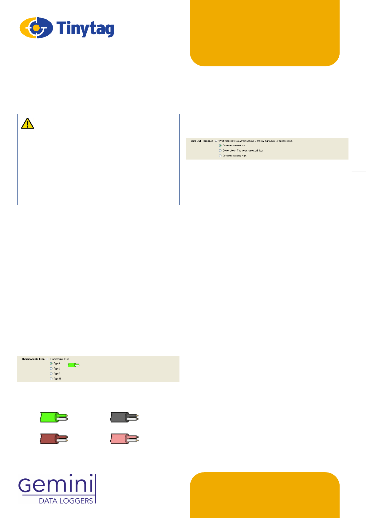
Select the thermocouple type you are using from the options listed.
If you are unsure what type of thermocouple you have, the plug or cable on it may
be coloured coded and you can match this to the diagram next to each option.
Colours for the different types of thermocouple are as follows:
ThermocoupleLogger
Burnout Response
Burnout Response
Burnout ResponseBurnout Response
The burnout response option allows you to tell the data logger what to do in the
event of a problem with the thermocouple being used.
If a faulty thermocouple is attached to the data logger it is possible for the logger
to show readings that may appear to be correct. The burnout response can
deliberately drive readings low or high in the event of a problem, to make it clear
to the user that there is a problem.
Choose what you want the data logger to do from the options listed.
Using the Thermocouple Data Logger
Using the Thermocouple Data Logger
Using the Thermocouple Data LoggerUsing the Thermocouple Data Logger
To get the best results, ensure that the data logger and the thermocouple plug
have sufficient time to reach the same temperature before recording begins. If the
thermocouple has been stored at a significantly different temperature from the
logger, allow 30 minutes for stabilisation.
It is advisable to keep the logger at a constant temperature whilst recording, and
to avoid large temperature gradients across the unit (for example, avoid placing
the logger on a very hot or very cold surface).
Large fluctuations in logger temperature can cause temporary errors in the probe
measurement, although these are unlikely to exceed 1°C.
Measurement Specification
Measurement Specification
Measurement SpecificationMeasurement Specification
Thermocouple
Thermocouple
Thermocouple Thermocouple
Sensor Type Type K, J, T or N Thermocouple
Sensor Type
ensor Type Sensor Type
S
Range
Range
RangeRange
Type K
Type K -270 to +1370°C (-454 to 2498°F)
Type KType K
Type J
Type J -210 to +1200°C (-346 to 2192°F)
Type JType J
Type T
Type T -270 to +400°C (-454 to 752°F)
Type TType T
Type N
Type N -270 to +1300°C (-454 to 2372°F)
Type NType N
Reading Resolution
Reading Resolution 0.01°C
Reading Resolution Reading Resolution
Cold Junction Compensation
Cold Junction Compensation -10 to +70°C
Cold Junction CompensationCold Junction Compensation
Accuracy
Accuracy Better than ±1.0°C across all thermocouple
AccuracyAccuracy
Note: The above accuracy figures do not include the thermocouple probe.
Logger Temperature
Logger Temperature
Logger TemperatureLogger Temperature
Range
Range -40 to +85°C (-40 to +185°F)
RangeRange
Sensor Type
Sensor Type 10K NTC Thermistor
Sensor Type Sensor Type
Response Time
Response Time 20 mins to 90% FSD in moving air
Response TimeResponse Time
Reading Resolution
Reading Resolution 0.02°C or better
Reading Resolution Reading Resolution
Accuracy
Accuracy Better than ±0.5°C
AccuracyAccuracy
ranges when the logger is between
-10 & +70°C.
Type K
Type K Type J
Type KType K
Type T
Type T Type N
Type TType T
…………………………………………………………………………….
Type J
Type JType J
Type N
Type NType N
ThermocoupleL
ogger
………………………………………………………………………
Physical Specification
Physical Specification
Ph
ysical SpecificationPhysical Specification
Logger
Logger
LoggerLogger
IP Rating
IP Rating IP51
IP RatingIP Rating
Working Temperature Range
Working Temperature Range -40 to +85°C (-40 to +185°F)
Working Temperature RangeWorking Temperature Range
Case Dimensions
Case Dimensions
Case DimensionsCase Dimensions
Height
Height 42mm / 2.83”
HeightHeight
Width
Width 60mm / 2.36”
WidthWidth
Depth
Depth 33mm / 1.30”
DepthDepth
Weight
Weight 65g / 2.29oz
WeightWeight
Supplied Type K Thermocouple
Supplied Type K Thermocouple
Supplied Type K ThermocoupleSupplied Type K Thermocouple
Temperature Range
Temperature Range -100 to +250°C (-148 to 482°F)
Temperature RangeTemperature Range
Lead length
Lead length 1m / 39.37”
Lead length Lead length
Battery Information
Battery Information
B
attery InformationBattery Information
Battery Type
Battery Type Tekcell SBAA02P;
Battery TypeBattery Type
The logger will operate with other ½AA 3.6V Lithium (Li-SOCl2) batteries but
performance cannot be guaranteed.
Replacement Interval
Replacement Interval Annually
Replacement Interval Replacement Interval
Before replacing the battery the data logger must be stopped.
Data stored on the logger will be retained after a battery is replaced.
LED Flash Patterns
LED Flash Patterns
LE
D Flash PatternsLED Flash Patterns
When logging, status LEDs on the front of the logger will flash as follows:
Flash Pattern
Flash Pattern Indication
Flash PatternFlash Pattern
A green flash every 4 seconds Logging
A green flash every 8 seconds Waiting to log (set for a delayed start)
A red flash every 4 seconds Alarm limit breached
For more information on the alarms and how they work, please see the Tinytag
Explorer quick start guide and help file.
Notes
Notes
N
otesNotes
If used at low temperatures the data logger should be allowed to warm to room
temperature before it is opened to avoid condensation forming inside it.
The IP51 rating is valid only when the logger’s connector cover is fitted and the
unit is orientated with it’s hanging tab uppermost.
Trigger Start
Trigger Start
Trigger Start Trigger Start
The trigger start option allows a logger to be set up as required and then started
at a later time with a magnet. The position of the trigger start switch is indicated
by the • • • marking on the back of the logger. When the "Wait until trigger
event" option is selected in the Tinytag Explorer software the green LED on the
logger will flash once every eight seconds to indicate that it is waiting to start.
When a magnet is swiped past the • • • marking, the green LED will light to
indicate the switch is closed. After the magnet has been removed, the green LED
will flash every four seconds to indicate that the logger is recording.
SAFT LS14250 or LST14250
Indication
IndicationIndication
…….
Calibration
Calibration
C
alibrationCalibration
This logger is configured to meet Gemini’s quoted specification during its
manufacture.
We recommend that the calibration of the logger should be checked annually
against a calibrated reference meter.
A certificate of calibration, traceable to national standards, can be supplied for an
additional charge either at the point of purchase, or if the logger is returned for a
service calibration.
Approvals
Approvals
A
pprovalsApprovals
Gemini Data Loggers (UK) Ltd. operates a Business Management System which
conforms to ISO 9001 and ISO 14001.
Warranty
Warranty
W
arrantyWarranty
This product carries a manufacturing defects warranty of 12 months from the date
of purchase. Units returned under warranty will be repaired or replaced at the
manufacturer’s discretion. This warranty does not cover mishandling, modification
or battery replacement and is subject to the standard Terms and Conditions of
Sale, a copy of which is available on request.
The equipment/goods are sold “as is” and with “all faults” (applies in USA).
The equipment/goods are sold “as is” and with “all faults” (applies in USA).
The equipment/goods are sold “as is” and with “all faults” (applies in USA). The equipment/goods are sold “as is” and with “all faults” (applies in USA).
Claims under warranty should be referred to the point of sale.
Claims under warranty should be referred to the point of sale.
Claims under warranty should be referred to the point of sale.Claims under warranty should be referred to the point of sale.
Disposal
Disposal
D
isposalDisposal
Data loggers, accessories and batteries should be disposed of at
organised facilities, where available, in compliance with local
regulations.
In accordance with the WEEE directive Gemini Data Loggers (UK) Ltd.
will take back and dispose of any equipment purchased directly.
Equipment not purchased directly should be returned to the point of
sale for disposal.
Further Information
Further Information
rther InformationFurther Information
Fu
Further information on Tinytag data loggers, software and accessories can be
found on our web site at:
www.micronmeters.com
If you should have any further questions, please contact your distributor or:
Gemini Technical Support
Gemini Technical Support
Gemini Technical SupportGemini Technical Support
metersinfo@micronmeters.com
………………………………………………………………….
…………
9800-0116: Issue 3 (17th October 2014)
 Loading...