

Page 1
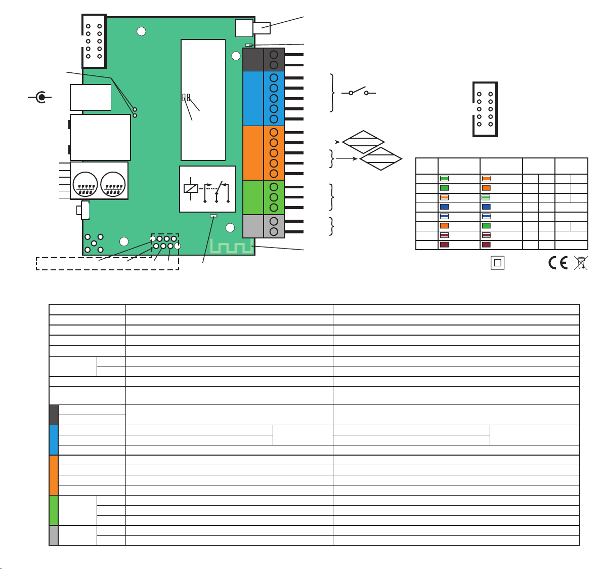
passive PoE
–
green LED
orange LED
SCL – 1
+5V – 2
SDA – 3
1wire – 4
GND – 5
+3,3V – 6
Firmware update – via website.
2101
IDC10
jumper
+
9
POWER
max 58 V
ETHERNET
Modbus
module
RX LED
TX LED
100 Mbit
PoE 802.3af
RJ12
1WIRE
RESET
BUTTON
Console pins
Component/PIN Description Opis
power LED LED indicator on – power on board Świecąca dioda LED oznacza zasilanie płytki
relay LED LED indicator on – relay active Świecąca dioda LED sygnalizuje aktywność przekaźnika
Ethernet LED
RESET button
INPD4, INPD3, IN PD2 Logical inputs; Low= 0 ÷ 1.0 V, High= 1.3 ÷ 30 V
INPA 2, IN PA1 Analog inputs; voltage range 0.1÷3.3 V or 0÷58 V Wejścia analogowe; napięcie 0,1÷3,3 V lub 0÷58 V
OUT1
OUT6
Aktualizacja rmware – przez stronę internetową.
I2C
TX console +5V Reset
GND
Power Power supply 8 ÷ 58 V DC Napięcie zasilające 8 ÷ 58 V DC
IDC10 Outputs: PWM1÷PWM3 / OUT2÷OUT5 / +5 V / POWER Wyjścia: PWM1÷PWM3 / OUT2÷OUT5 / +5 V / POWER
green LED indicator on – eth link active Świecąca dioda LED sygnalizuje aktywne połączenie Ethernet
orange LED indicator on – data transmitted Świecąca dioda LED sygnalizuje przesyłanie danych
RJ 12 1WIRE and I2C buses for sensors Magistrale 1WIRE i I2C dla czujników
B–
A+
INPD1 Logical inputs; Low= 0 ÷ 0.3 V, High= 0.8 ÷ 30 V Wejścia logiczne; Low= 0 ÷ 0,3 V, High= 0,8 ÷ 30 V
GND Ground for analog and digital inputs Ogólna masa dla wejść analogowych i cyfrowych
+3.3 V Only for sensors supply Wyłącznie do zasilania czujników
INPA 3 Analog inputs; voltage range 0.1÷5 V or 0÷58 V Wejścia analogowe; napięcie 0,1÷5 V lub 0÷58 V
+5V Only for sensors supply Wyłącznie do zasilania czujników
short press – reverse relay output
long press – relay click double – restore default settings
Modbus RTU connector złącze Modbus RTU
NC Relay OUT1, normally closed contact Przekaźnik OUT1, normalnie zamknięty
C Relay OUT1, common contact Przekaźnik OUT1, styk wspólny
NO Relay OUT1, normally open contact Przekaźnik OUT1, styk normalnie otwarty
PWR Transistor output (+), voltage = power supply, max 0.75 A Wyjście tranzystorowe (+), napięcie = zasilanie, max 0,75 A
GND Ground for transistor output (–) Masa dla wyjść tranzystorowych (–)
OUT1
NO NCC
relay LED
LTE antenna (*)
(*) depending on
the device version
power LED
B–
A+
INPD4
INPD3
INPD2
INPD1
GND
+3.3 V
INPA3
INPA2
INPA1
+5 V
NC
C
NO
PWR
GND
Wi–Fi antenna
Also support
a pulse counter
LK4 terminal diagram
LOGIN/PASS: admin / admin
IP address: use LK Tools for checking IP adress
4x
0÷30V
A
0.1÷5 / 58V
A
0.1÷3,3 / 58V
OUT1
OUT6
www.tinycontrol.eu
krótkie naciśnięcie – odwrócenie wyjścia przekaźnikowego
długie naciśnięcie – podwójne kliknięcie przekaźnika – przywraca ustawienia fabryczne
Wejścia logiczne; Low= 0 ÷ 1,0 V, High= 1,3 ÷ 30 V
1–
PWM1
3–
+5 V
5–
GND
7–
PWM3
9–
POWER
Ethernet PoE info
Plug Colors A
Pin1
white-green
Pin2
green
Pin3
white-orange
Pin4
blue
Pin5
white-blue
Pin6
orange
Pin7
white-brown
Pin8
brown
IDC10
2101
PWM2
9
Colors B
white-orange
orange
white-green
blue
white-blue
green
white-brown
brown
Obsługują dodatkowo
licznik impulsów
OUT5
OUT4
OUT3
OUT2
IP20
–2
–4
–6
–8
–10
jumper option
Alternative B
Rx+
Rx–
Tx+
Tx–
DC+
DC+
DC–
DC–
default
Alternative A
Rx+ DC+
Rx– DC+
Tx+ DC–
Tx– DC–
not used
not used
not used
not used
 Loading...