

Tinycontrol Lan Controller v3, LANKON-008 User Manual
LAN Controller V3.0
Manual

2
manual LAN Controller V3.0 – LANKON-008
www.tinycontrol.eu
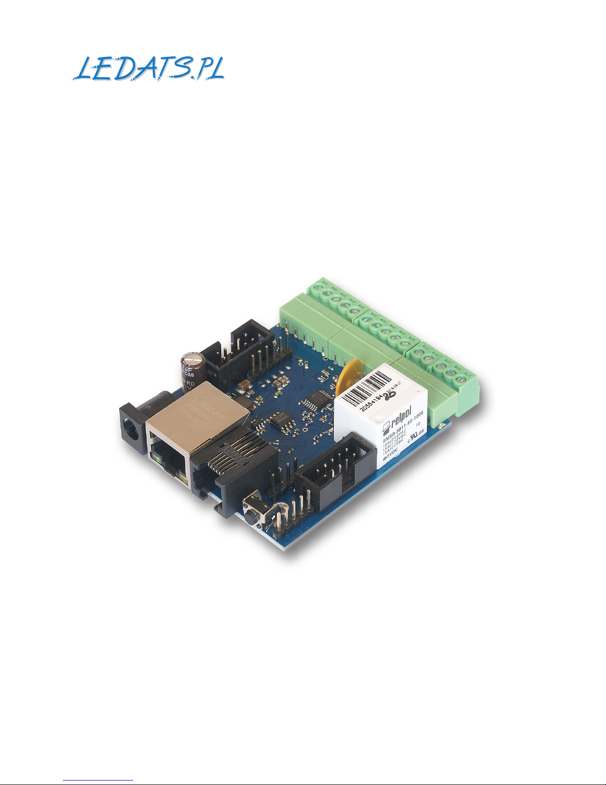
LAN Kontroler
Lan Controller v3 is a completely new version of device produced from 2011y.
A small board works as a web server which presents the various sensor readings: temperature, humidity, voltage, current, events and allows you to remotely control up to 10
outputs.
Modern 32bit processor, additional ash chip, regulated amplier for measurements allow not only for more features but innovative web interface. Thanks communication between hardware and web browser by XML les it is possible to design own web interface,
which t much better to end customer demands as our universal and should be easiest to
use for specic functionality. We hope to acquire new applications thanks it.
Lan Controller talks with computers and Internet network using universal protocols
like HTTP and SNMP. In new version we add support for MQTT now and we launched free
(up to 5 devices) cloud mqtt.ats.pl. It allow to collect, processing and present as a graph
all data sent by Lan Controller.
Specic functionality of MQTT protocol allow control outputs from Internet even if device is located in local network behind router.
Example of applications
•in industry: machines, technological lines, working environment monitoring;
•in markets: refrigerators remote monitoring;
•in oces and workplaces: cooperation with access systems, observation
of environmental conditions;
•at home: for heaters automation, lighting according dust sensor or scheduler,
garden watering systems;
•at home: for controlling temperature in heating installations, heat pumps,
solar installations;
•renewable energy: measurements of productivity of PV installations, battery charging,
AC power consumption and production measurements;
•in farms and garden: monitoring and controlling greenhouses, watering, food dispensing
machines for animals.
We invite you to visit our website
www.tinycontrol.eu
There you will nd the rmware updates and information about the new possibilities.
MQTT broker
cloud services
router

manual LAN Controller V3.0 – LANKON-008
3
www.tinycontrol.eu
Monitoring, Controlling, Restarting
FEATURES:
•4 analog inputs
•2 analog inputs up to 3,3V - for DC voltage, DC current or other physical quantities by
voltage output sensors,
•digital buses: 1wire - up to 6 DS18B20 temperature sensors, I2C - up to 2 sensors, for
example AM2320 humidity sensor,
•4 logical inputs, as state (high, low) sensors (open, close, PIR) and for pulse counters
from energy meters,
•1 relay on board, (NZ,C,NO),
•1 transistor output, same voltage as supply, for loads up to 1A,
•4 outputs OC standard, for switching relays or small power loads
•4 PWM outputs, works as PWM, on/o and servos control*
•UART port for communication with PV DC/AC Inverters like Duraluxe, SDS011 AIR quali-
ty sensor or other devices
•communication option for LoRa and GSM modules*
•temperature and supply monitor on board
•modern and convenient web interface with pule down menu
•possibility of modication web interface or build new from scratch by www generator
•possibility of conguration Status panel, upload own background (with drawing of in-
stallation) and setting of sensor and outputs windows visibility
•logging as administrator for conguration and user for status preview
•advanced Even Cong with checking if 2 conditions are fullled
•support for: SNMP, HTTP GET/POST request or all MQTT protocols
•free access (up to 5 devices) to mqtt.ats.pl cloud for collecting, computing and visuali-
zation of data.
•remote controlling of outputs from Internet and mobile device even if LAN Controller
is behind router*,
* option possible in future.
Lan Controller is innovative device for remote controlling and measuring by LAN network
and internet. Because of many measurement features, many conguration possibilities
and embedded automatization are of application is only limited by user imagination. But
it cause that our company as a producer is not able to test all possible congurations and
it could happen that ones of setting will not work according to your expectations. In all
such cases please mail to info@tinycontrol.pl
But in rst place we ask to read this manual carefully. As a rich source of information
also serves user forum http://tinycontrol.pl/forum/
You are invited to use and share you experience!

4
manual LAN Controller V3.0 – LANKON-008
www.tinycontrol.eu
FACTORY SETTINGS
•IP address of the module: 192.168.1.100
•administrator: admin password: admin
•user: user password: user
TECHNICAL SPECIFICATIONS
•supply voltage: 8 ÷ 55 V DC
•power consumption: 0,5W - without an attached relays
•PoE supply: YES, passive (PoE max. <55 V)
•Protection from wrong supply polarization: YES
•interface: Ethernet 100 Mbit/s
•relay: 255 V AC 10 A
•operating temperature: –20 to +85 °C
•weight: 50 g
•dimensions: 67 x 68 x 39 mm + DIN socket (can be mounted on DIN rail)
INPUT / OUTPUT:
•4 ANALOG INPUTS INPA1÷INPA4 WITH AMPLIFIER - 2 input voltage ranges:
The scope of of measured voltage for a range of 3.3 V
gain=1 from 0 to 3300 mV
gain=10 from 0 to 330 mV
gain=50 from 0 to 60 mV
The scope of of measured voltage for a range of 33 V
gain=1 from 0 to 33000 mV
gain=10 from 0 to 3300 mV
gain=50 from 0 to 600 mV
for voltages between 0 ÷ 5 mV, the measurement is not sure.
•2 ANALOG INPUT WITHOUT GAIN INPA5÷INPA6:
range of measured voltage of 0.1÷3.3 V
•1 DIGITAL INPUT in standard 1-WIRE and I2C (connector 6P6C RJ12):
measurement 6 temperature probes DS18B20 and the temperature and humidity sensor AM2320
•4 LOGIC INPUT:
VLow - max 1,1 V
VHigh - min 1,5 V, max 12 V
•1 RELAY:
10 A / 240 V AC, 15 A / 24 V DC
3 styki: NZ, NO, C
•1 TRANSISTOR OUTPUT:
giving adequate voltage to control receivers with current consumption up to 1A
•4 OUTPUT OUT1÷OUT4 (connector IDC10-2):
OC output of 100 mA, controlled downside to switching relays, transistors, etc.
•4 PWM OUTPUT:
the output frequency range of 50 Hz to 100 kHz
•UART - serial - console preview functioning of the Lan Controller system:
Transmission parameters: 115200 bitrate, 8 N 1
manual LAN Controller V3.0 – LANKON-008
5
www.tinycontrol.eu
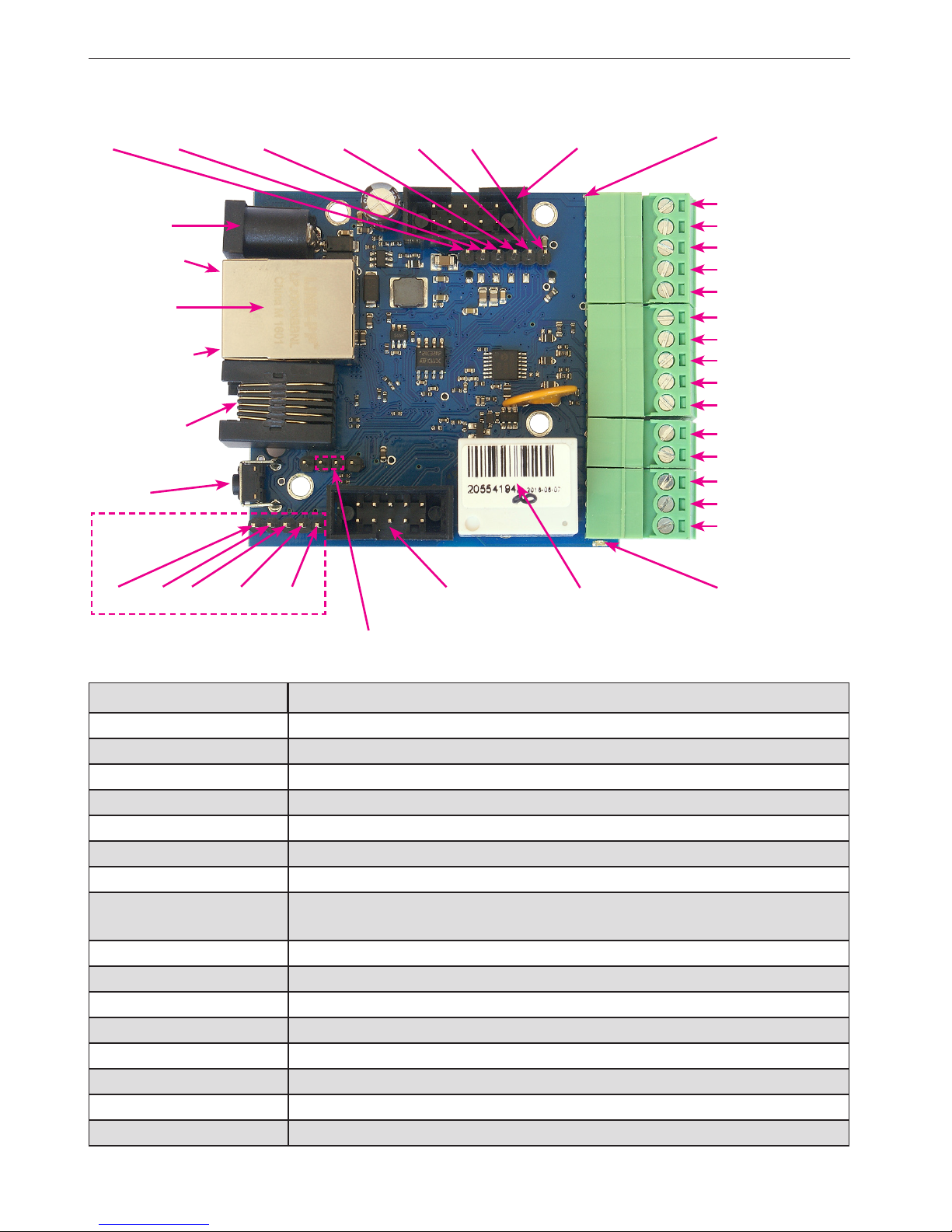
PINS and COMPONENTS DESCRIPTION
service jumper pins
Ethernet
100 Mbit.
PoE max 55V
IDC10-1
INP3D
INP4D
+5V
OUT5=V power
GND
NC
C
NO
Zasilanie
max 55V
power LED
relay LED
INP6
RJ12 6p6c
1wire
REL AY OUT0
INP1D
INP2D
GND*
- Ground for analog
and digital inputs
IDC10-2
RESET
green LED
orange LED
digital
inputs
}
PIN/Component Description
Power Power supply 8V ÷ 55V DC
power LED LED indicator on – power on board
relay LED LED indicator on – relay active
green LED LED indicator on – eth link active
orange LED LED indicator on – data transmitted
IDC10-1 Additional Inputs / Outputs PWM1÷3
IDC10-2 Additional outputs transistor OC standard, for example, relays
INP1D÷INP4D
Logical inputs Low=0~0,8V, High=0,8V~20V
Also supports a pulse counter
+5V For sensors supply
GND* Ground for analog and digital inputs
INPA1÷A4 Analog inputs
OUT5 Transistor output (+), voltage = power supply, max 1A
GND Ground for transistor output (–)
NC Relay OUT0, normally closed contact
C Relay OUT0, common contact
NO Relay OUT0, normally open contact
INPA3
INPA4
GND*
INPA1
INPA2
analog
inputs
}
GND SPI_SDO SPI_SCK SPI_SDI SPI_CS +3,3V
GND RX TX +3,3 V +5 V
Console pins
6
manual LAN Controller V3.0 – LANKON-008
www.tinycontrol.eu
Outputs connection - relay OUT0:
NC – contact normaly closed
C – common contact
NO – contact normaly open
CAUTION: Although the relays are able to switch alternating voltage 255VAC 10A,
the same Lan Controller does not meet the safety requirements for connection to
dangerous voltages for unauthorized persons (unsecured plugs, no ground). Such
a system can make a person authorized and properly secure the device in a closed
box, eg. Electricity. It is safer to also use external relays eg. DIN rail switching high
voltage and only the controlled from Lan Controller.
NO C NC
RESET BUTTON
Pressing for about 0.5 seconds to change state relays, and hold for longer - up to around
ve seconds will change all settings (both network and conguration) on the factory reset. Conrmation of the settings is fast switching on and o the relay (click-click), not to be
confused with the change of status and exclusion of the relay after a reboot.
login as an administrator: user: admin password: admin
IP: 192.168.1.100
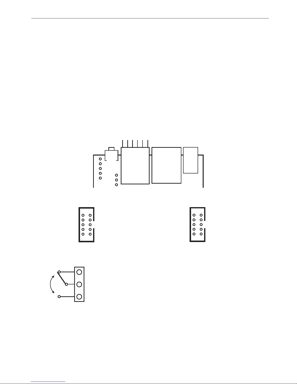
IDC10-1
9 – +5V
7 – UART_RX
5 – GND
3 – +3,3 V
1 – UART_TX
GPIO1 –10
GPIO2 – 8
PWM3 – 6
PWM2 – 4
PWM1 – 2
IDC10-2
9 – POWER
7 – PWM0
5 – GND
3 – +5V
1 – INPA5
OUT1 –10
OUT2 – 8
OUT3 – 6
OUT4 – 4
INPA6 – 2
ETHERNET
100 Mbit
PoE max 55 V
SCL – 1
+5V – 2
SDA – 3
1wire – 4
GND – 5
+3,3V – 6
INP6
RJ-12 6p6c
1wire
RESET
POWER
max 55 V
DESCRIPTION OF CONNECTORS:
RJ12 6P6C (1-wire bus, I2C), IDC10-1, IDC10-2:
manual LAN Controller V3.0 – LANKON-008
7
www.tinycontrol.eu
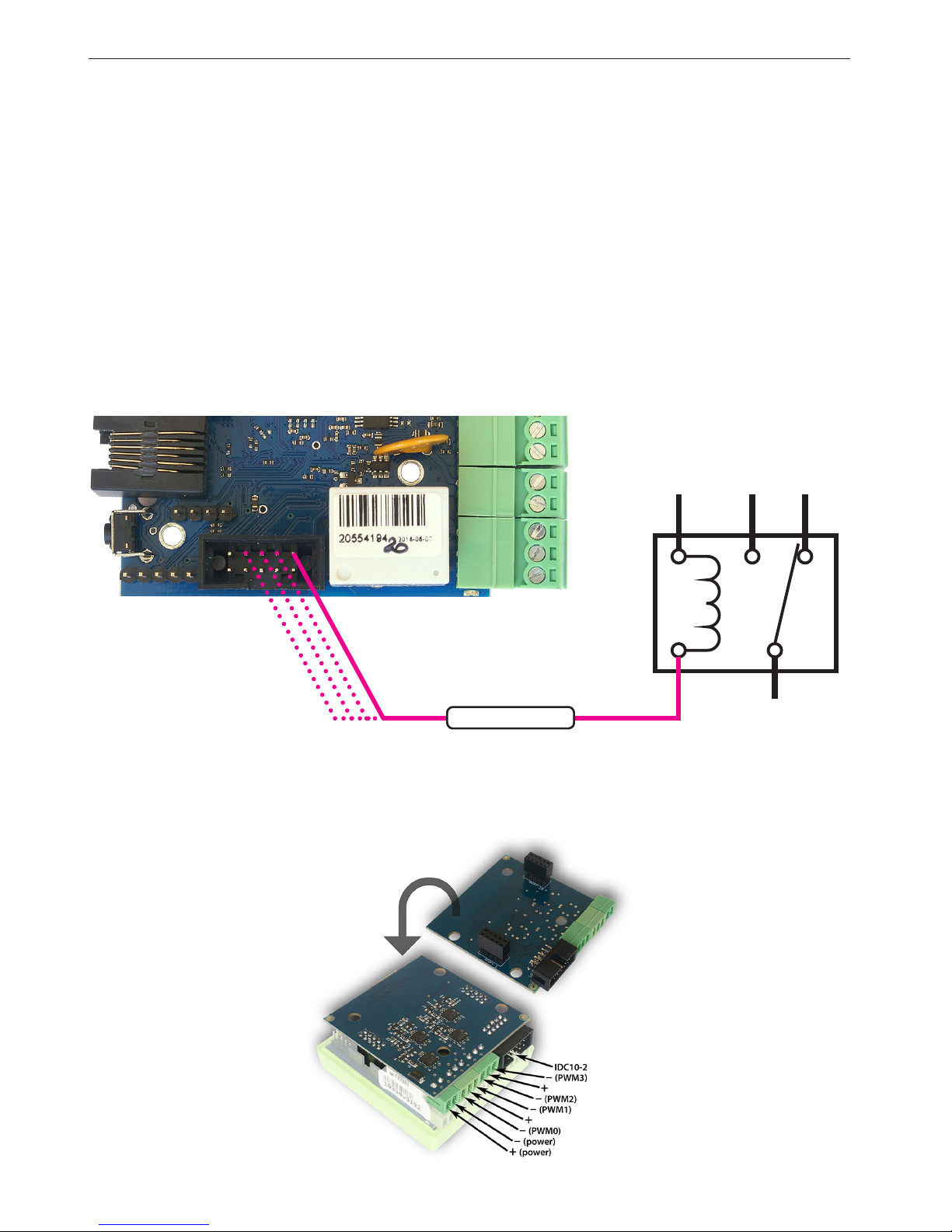
IDC10-2 socket: Connection OUT1÷OUT4
OUT1÷OUT4 are open collector, it means that the switching means connecting mass of
the system.
So, it can be actuated, for example relays, motors of low power (fans), connecting on the
one hand to the output OUT "–" (mass), and on the other hand, "+" supply.
For relays with 12V coils or fans use an external 12V power supply.
In the case of the nished plate 4-ch relay can plug them supplied with them tape outlet
IDC10-2. The relays are then fed from the internal 5V.
CAUTION: For relays with more power switched due to the higher power consumption,
it is recommended to use an external power supply, for example, 12V or 24V. + 5V voltage from the Lan Controller board is also used to power sensors and should not be
charged more strongly than 300mA.
Connecting the PWM outputs on transistor circuit extension (optional)
+12V
OUT1÷OUT4
coil relay
8
manual LAN Controller V3.0 – LANKON-008
www.tinycontrol.eu
SENSORS CONNECT
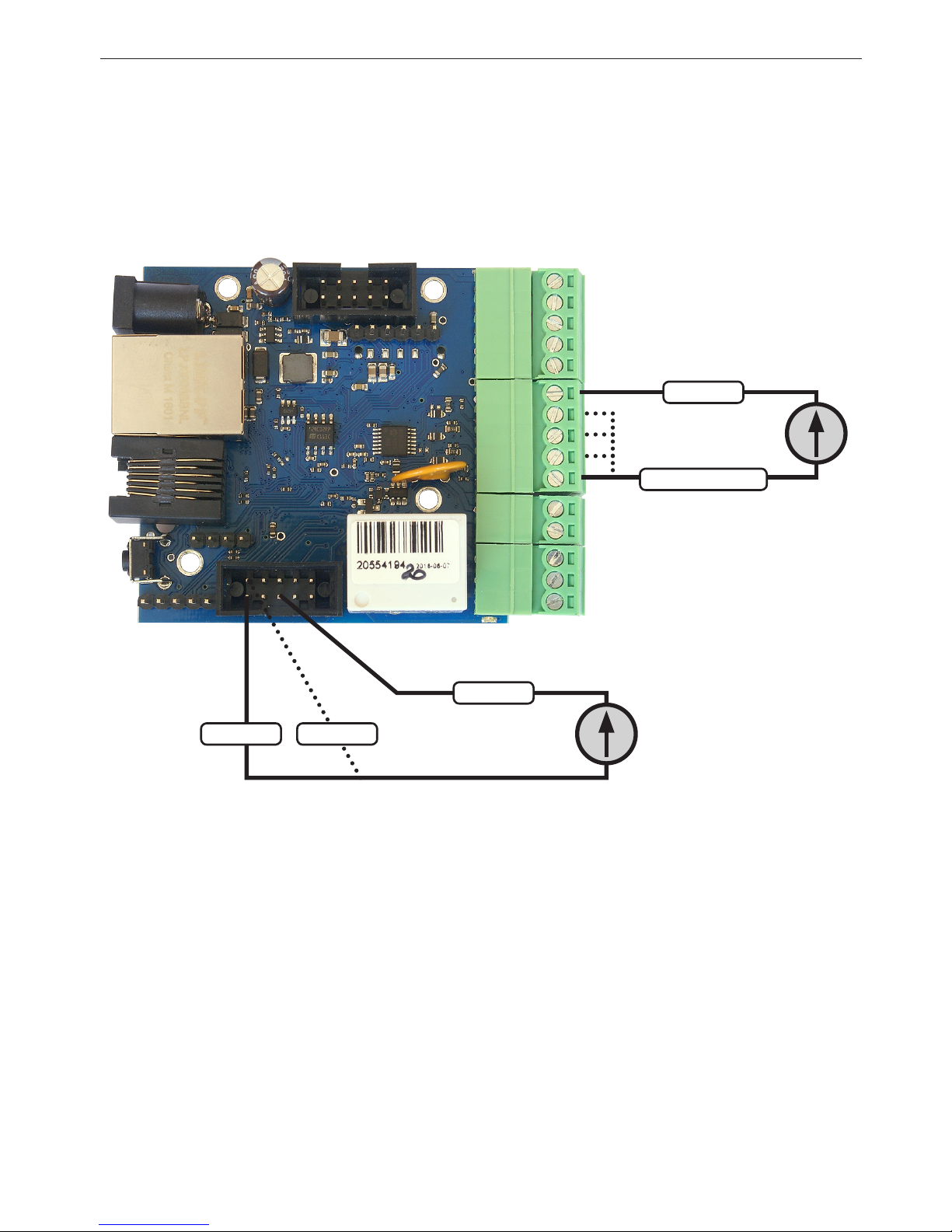
1. Measurement of DC voltage at the inputs INPA1÷INPA4 (3÷33V)
To enable the measurement to be in the "Input" to choose for INPA1÷INPA4 range
Vin = 3.3V or 33V, and possibly small signal strengthening GAIN.
For INPA5 and INPA6 can turn on only 3.3V range.
Measured voltage:
0 ÷ 3.3 V DC
Measured
voltage:
0 ÷ 3.3 V DC
0r
0 ÷ 33 V DC
GND
GND
INPA6
Pin5
Pin2Pin1
INPA1÷INPA4
INPA5
manual LAN Controller V3.0 – LANKON-008
9
www.tinycontrol.eu
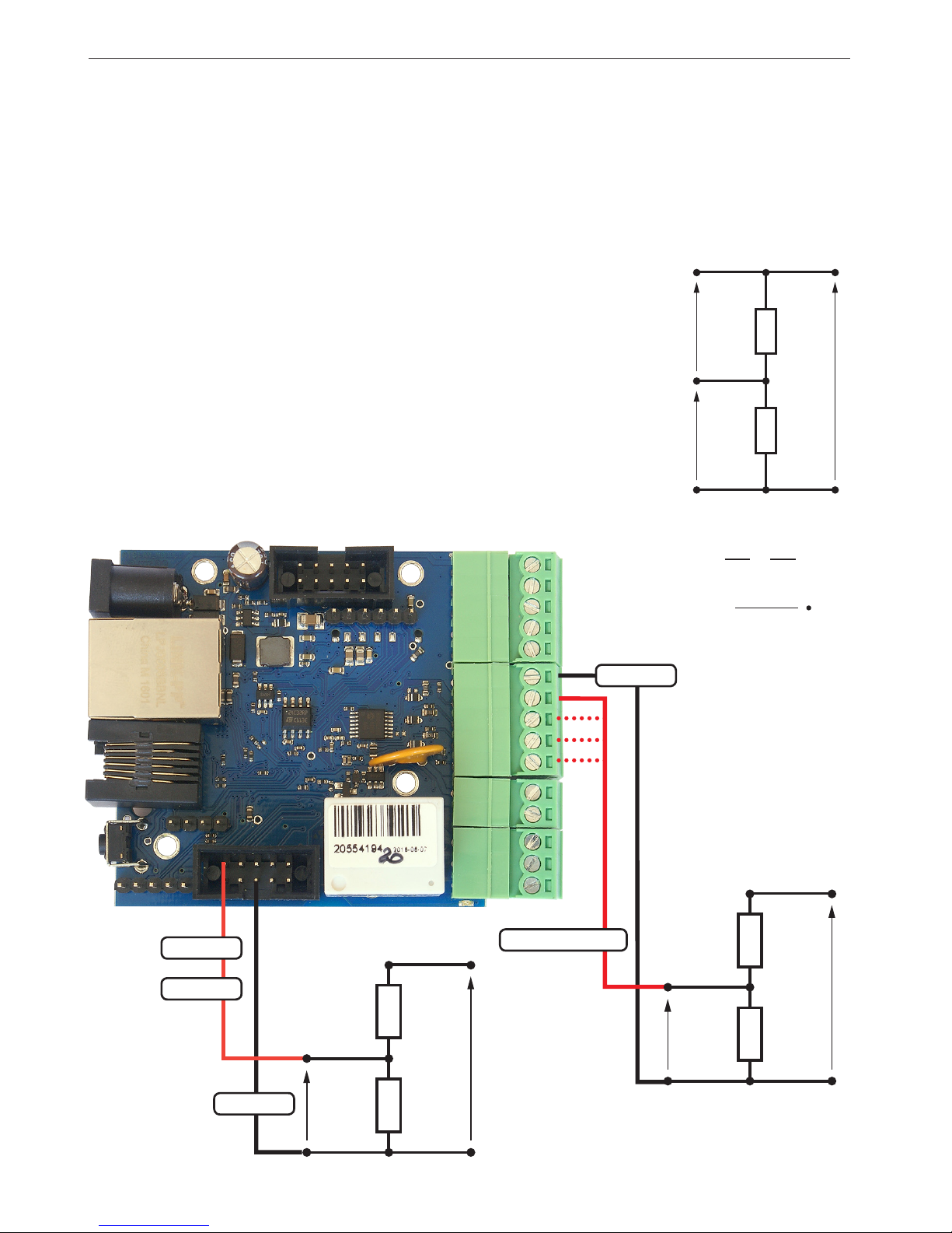
2. Measurement of the DC voltage through resistive divider
If you need to measure the voltage higher than 33V to INPA1÷INPA4 or 3.3V on INPA5,
INPA6 use a resistive divider. U voltage dividers connected to the terminals should be safe,
or properly protected against accidental shock hazard.
WARNING: The supply voltage of long cables exposed to lightning, for example, the photovoltaic system can result in the transfer of electrical charge on the sensitive input Lan
Controller and can cause damage.
R
1
R
1
U
U = U
1
+ U2
U
=
R
2
R
2
U
1
U
1
U
2
U
2
R1 + R
2
=
R
2
U
2
EXAMPLE
U – Input voltage for the measurement
U2 – the voltage at the input INPA1÷INPA4 or INPA5, INPA6
for the measurement of up to 33 V at the input INPA5 or INPA6 (max. 3.3 V)
should be used divider:
R1 = 9 kΩ, R2 = 1 kΩ,
for the measurement of up to 360 V at the input INPA1÷INPA4 (max. 33 V)
should be used divider:
R1 = 99 kΩ, R2 = 10 kΩ,
As a result of the multiplier enter of sharing: U / U
2
Pin1
GND
INPA1÷INPA4
R
1
U
R
2
U
2
R
1
U
R
2
U
2
GND
INPA6
Pin2
Pin5
INPA5
10
manual LAN Controller V3.0 – LANKON-008
www.tinycontrol.eu
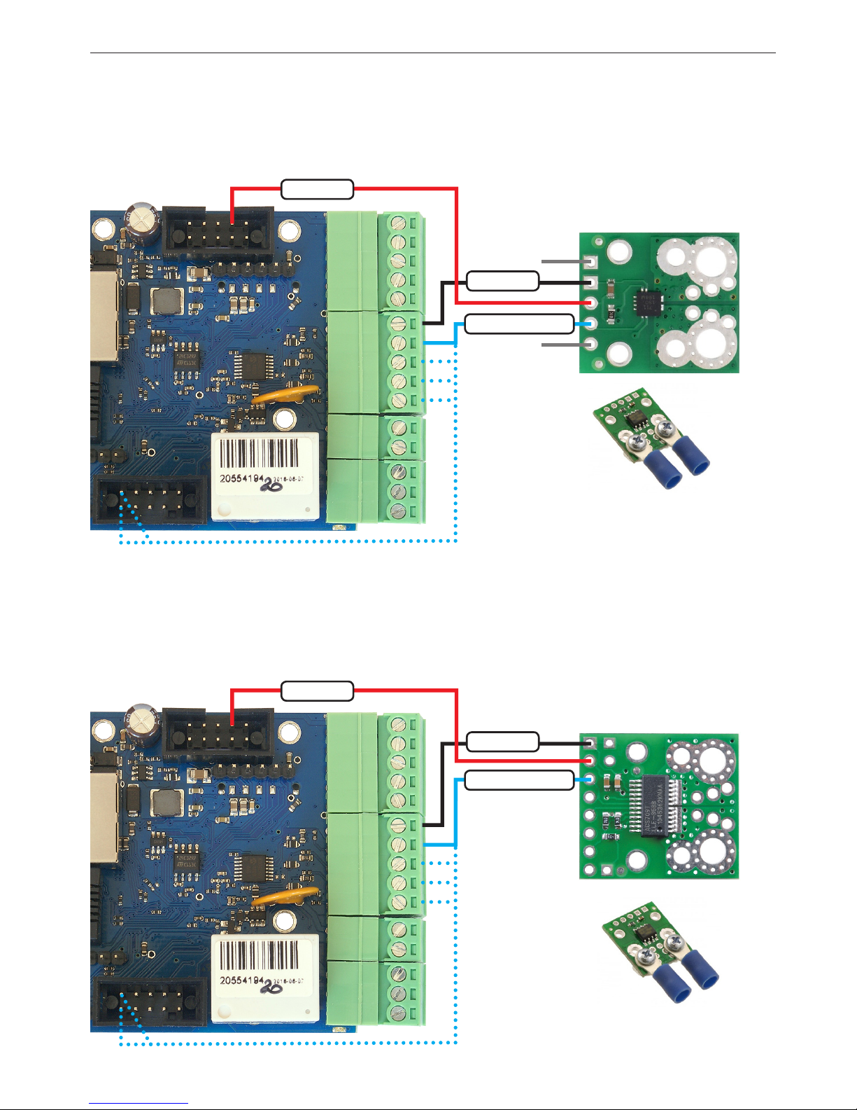
4. Connection the current sensor ACS709
GND
FAU LT
Recommended
installation of cables
Recommended
installation of cables
3. Connection the current sensor ACS711ex
IP+
IP+
IP–
IP–
The sensor can measure DC currents to 15A or 30A (depending on the version of the sensor).
It can be connected to all analog inputs: INPA1÷INPA6.
Power supply: + 3.3V (pin 3 of the output IDC10-1).
The sensor can measure DC currents to
75A.
It can be connected to all analog inputs: INPA1÷INPA6.
Power supply: + 3.3V (pin 3 of the output IDC10-1).
GND
GND
Pin3
Pin3
INPA1÷INPA6
INPA1÷INPA6
+3,3V
+3,3V
manual LAN Controller V3.0 – LANKON-008
11
www.tinycontrol.eu
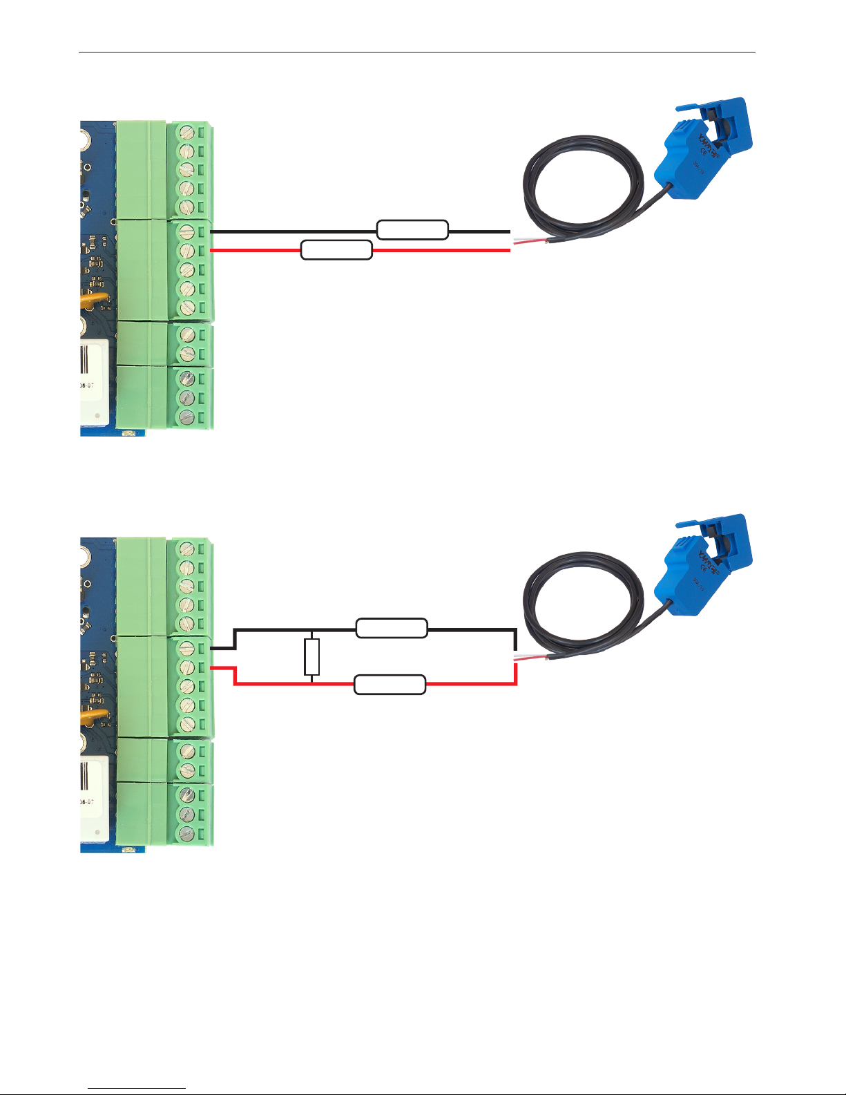
5. Connection of the AC sensor SCT 013 030
6. Connection of the AC sensor SCT 013 000
The sensor can measure AC currents up to 30A with a resolution of
about 50mA, but for a power supplies of low PF, measurement inaccuracies can be signicant. The sensor does not require a separate
power supply.
red
red
INPA1
GND
white
white
180 Ω
The sensor can measure the AC current. This model does not have an internal resistor
which is conducted to measure, and therefore for a measurements to about 26A, connect
the 180 Ω resistor in parallel to the terminals (INP and GND). The displayed value will be
real. For measurements higher currents should give smaller resistor and proportionally
multiply displayed current.
For example: to increase the range x3 (78A) must be used resistor 60,4 Ω
to increase the range x4 (104A), use a resistor of 45,3 Ω
INPA1
GND
 Loading...