

Page 1

Manual
LAN Controller V2.0
Firmware:
HOME: from 3.13
ISP: from 2.09
Page 2

manual LAN Controller V2.0 – Firmware: HOME v. 3.13 and ISP v. 2.09 – LANKONT-002
LAN Controller
LAN Controller is a simple, but innovative device which has long been lacking in the market network solutions. A small board serves as a web server which presents the various
sensor readings and allows you to remotely control up to 6 outputs. For far rom socket
installation board could be powered by passive PoE. In order to expand the uses of our
Lan Controller we introduced two types of management software (rmware) suitable for
dierent applications. In both versions, in addition to the main page of the Control Pa-
nel from the sensor readings are tabs: Events Cong for programming an array of events,
Scheduler for programming timed events and the Network Cong for all other settings.
Dierences (described further below) between rmware versions are as follows: 2.XX - ISP
version - contains an additional tab to set Watchdog to monitor 5-ve network devices.
3.XX - Home edition - is devoid of tabs Watchdog, but have been added: supports sen-
sor DHT22, reading to 6 temperature probes DS18B20, working digital inputs as bistable
switches - to use wall light switches. Changing the rmware is possible by the user program LAN Controller Tools.exe (Windows XP) or via the TFTP protocol - as described in this
manual at p. 25. In Accessory (www.tinycontrol.eu) are presented all sensors and upgrade
kits compatible with Lan Controller.
Examples of applications
ISP
• watchdog function to checking TCP/IP connection and launch outputs if hanging happen
•temperature, supply voltage and person occupancy control in server rooms
•weather condition report on the occasion of IP cameras views
Home control
•home electric stove control (automatically or remote)
•turning on/o home lightening remote, by scheduler or by event, controlling intensity
•turning o TV box if remote is other person hands ;-)
•irrigation control - you don’t need visit your garage to modify irrigation time or you can
turn sprayer precisely in the moment when your favorite neighbor passes near ;-)
Home installations
•temperature controlling and simple automation in your heating system
•temperature and pressure controlling in solar thermal installations
•measurements of heat pump operation
•monitoring of grid voltage and automatic switching to backup with mail notication
•remote control (by LAN or wirelesslan) understands as forwarding command to one of
output of Lan controller from input of other Lan controller
Renewable energy
•measurements of solar cells work
•measurements of wind turbines
•measurements of charging battery
•measurements of power consuming
Agriculture
•Irigation systems
•Animal food processing automatization
2
www.tinycontrol.eu
Page 3

manual LAN Controller V2.0 – Firmware: HOME v. 3.13 and ISP v. 2.09 – LANKONT-002
RESTARTER, MONITOR, CONTROLLER
FEATURES:
•WWW or SNMP v2 management
•rmware upgrade via TFTP
•read data in real time without refreshing page
•possibility switch on/o to 5 relay direct and 1 transistor output up to 1A from page
WWW
•events panel to self-programming by user
•Scheduler (switch on/o output for denite time in week days)
•IP watchdog to ve IP device (only v. 2.09)
•monitoring additional devices eg. PIR sensors
•environmental temperature and supply voltage on board measurement
•temperature and current measurement from connected sensors
•temperature and humidity measurement by DTH22 sensor (only v. 3.13)
•power measurement for DC voltage
•power measurement from grid by elecricity meterer impulse (only v. 3.13)
•possibility to connecting of the additional boards: with 4 switched PoE ports or 4 relays
•set time manualy or by server NTP
•posisibility sensors calibration
•frequency and duty modied PWM output
•remote control: each output of Lan controller setup as server can be controlled remo-
telly by LAN network from inputs of others Lan controllers
•e-mail notication about programmed events
•SNMP TRAP notication about programmed events
•automaticaly send state or value inputs to SNMP server by POST or GET commands
•implemented protocols: HTTP, SNMP, SMTP, SNTP, ICMP, DNS, DHCP.
•supported temperature sensors: PT1000, DS18B20
•support 1wire protocol
We hope that the LAN controller will have new applications not only in the ISP networks,
but most of all as a simple home automation, control the status of any type of installation, the measurement of renewable energy sources or as a simple measure of the energy
consumption of the various receivers. Therefore, the range of sensors will be expanded to
implement such measurements.
(may vary depending on the rmware version):
We invite you to visit our website
www.tinycontrol.eu
There you will nd the rmware updates
and information about the new possibilities.
3
www.tinycontrol.eu
Page 4

manual LAN Controller V2.0 – Firmware: HOME v. 3.13 and ISP v. 2.09 – LANKONT-002
FACTORY SETTINGS
IP address of the module: 192.168.1.100
user: admin
password: admin
TECHNICAL SPECIFICATIONS
•supply voltage: 8÷28 V DC
•power consumption : about 1W
•PoE supply: YES, passive (PoE max. <28V)
•Protection from wrong supply polarization: YES
•interface: ethernet 10Mbit/s
•relay: 255VAC 10A
•operating temperature: –20 to +85 °C
•weight: 50g
•dimensions (in a housing without plugs) 66 x 68 x 40 mm
INPUT/OUTPUT:
•5 ANALOG INPUTS:
temperature, voltage, current (by additional boards) and another physics measurements
•DIGITAL INPUT for 1WIRE bus (connector RJ11):
support for 4
•DIGITAL INPUT:
support temperature and humidity sensor DHT22
•4 LOGICAL INPUTS:
for monitoring, as a pulse counter from energy meter
•1 RELAY OUTPUT:
(NO, NC, C)
•1 TRANSISTOR OUTPUT:
up to 1A
•4 OUTPUTS (Connector IDC10-2):
to switch relays or transistors
•4 PWM OUTPUT:
2,6 KHz do 4 MHz
•measuring the temperature and supply voltage LAN Controller board
•reverse polarization protection
(v. 2.09)
or 6
(v. 3.13)
temperature sensors DS18B20
(only v. 3.13)
(only v. 3.13)
4
www.tinycontrol.eu
Page 5
manual LAN Controller V2.0 – Firmware: HOME v. 3.13 and ISP v. 2.09 – LANKONT-002
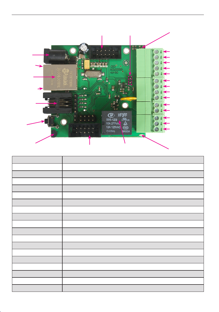
PINS and COMPONENTS DESCRIPTION
ID C10-1
Power
max 28V
green LED
Ethernet
10Mbit.
PoE max 28V
orange LED
INP6 - RJ11-
bus
1-Wire for
DS18B20
RESET
Temp. board sensor
PIN / Component Description
Power Power supply 8V ÷ 28V DC
power LED Shine LED means power on board
relay LED Shine means relay active
green LED Shine LED means eth link active
orange LED Shine means data transmitted
ID C10 -1 Additional outputs, for example, relays
IDC10-2 Additional Inputs / Outputs PWM1÷3
INP1÷4D Logical inputs Low=0~0,8V, High=0,8V~20V
INP4D
INP1 Input for voltage measure 0 ÷ 7.2V (3.6V if jumper on)
INP2 Input for voltage meas. 0 ÷ 36V
INP3 Input for PT1000 sensor for high temp. measure
GND General ground
OUT5 Transistor output (+), voltage = power supply, max 1A
GND Ground for transistor output (–)
NC Relay OUT0, normally closed contact
C Relay OUT0, common contact
NO Relay OUT0, normally open contact
Also supports a pulse counter
IDC10-2
jumper pins
REL AY OUT0
(only v. 3.13)
power LED
INP1D
INP2D
INP3D
INP4D
GND
INP1 - U 0÷7,2 V
INP2 - U 0÷36 V
INP3 - PT1000
GND
OUT5=Usupply
GND
NC
C
NO
relay LED
}
digital
inputs
5
www.tinycontrol.eu
Page 6
manual LAN Controller V2.0 – Firmware: HOME v. 3.13 and ISP v. 2.09 – LANKONT-002
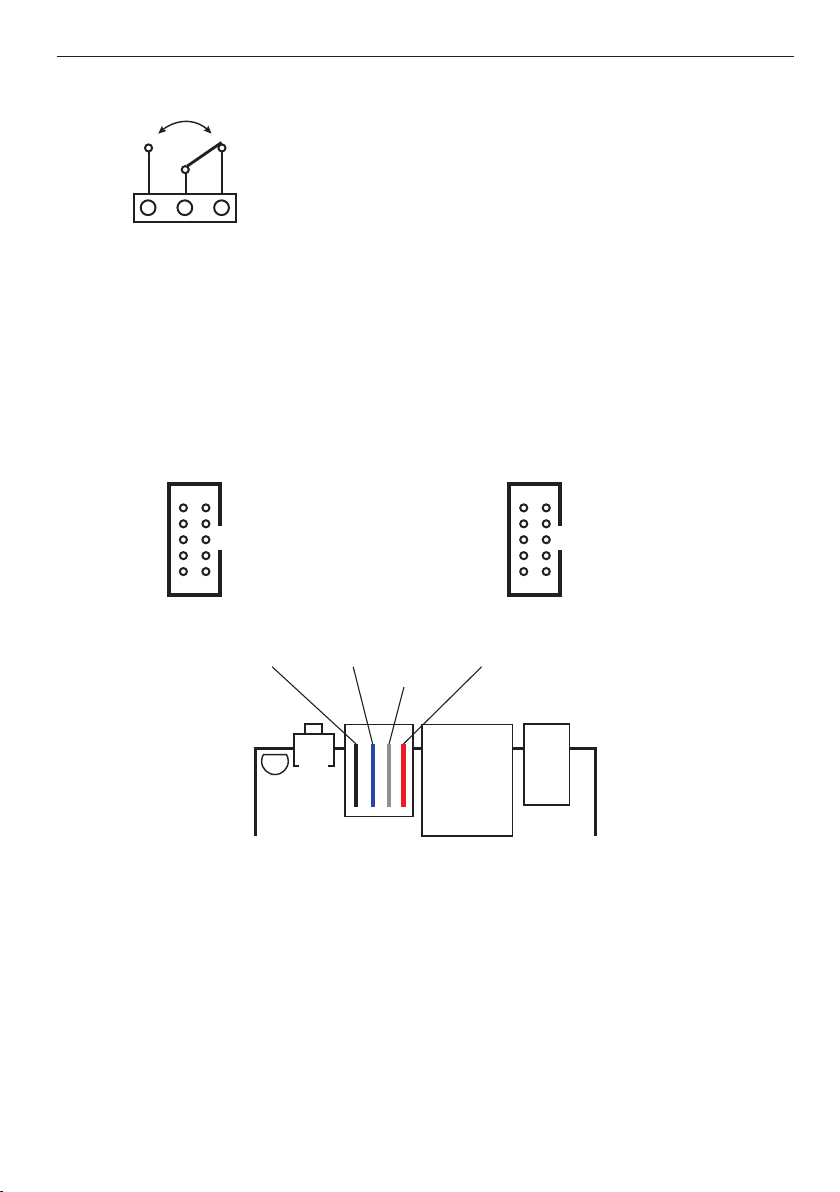
RELAY BOND:
NO – contact normaly open
C – common contact
NC – contact normaly closed
NO C NC
ATTENTION: In spite of that relay can switch AC voltage 255 VAC 10A, board fail to comply with safety requirements (lack housing, earthing). Therefore that receiver connect
with the assistance safety external relays eg. on DIN bus, controlled by relay on board.
IDC10-1, IDC10-2 and RJ11 (bus 1-WIRE):
OUT1–10
OUT2 – 8
OUT3 – 6
OUT4 – 4
– 2
IDC10-1
9 – VCC
INP5 –10
7 – PWM
5 – GND
3 – +3,6 V
1 –
GND 1-Wire VCC=3.6V
PWM2 – 6
PWM3 – 4
PWM1 – 2
not
IDC10-2
– 8
9 – VCC
7 – INP4
5 – GND
3 – +3,6 V
1 – DHT22
(only v. 3.13)
use
RESET
PoE max 28 V
10 Mbit
max 28 V
ETHERNET
POWER
RESET BUTTON
Pressing for about 0.5 seconds to change state relays, and withstand longer to near 5 seconds (when we’re not logged by the Web module) will reset the module, further detention for about 10 seconds to change all settings (both network and conguration ) on the
factory, reset conrmation of the settings is fast switching on and o the relay (click-click),
not to be confused with the change of status and exclusion of the relay after a reboot.
User and password: admin
IP: 192.168.1.100
6
www.tinycontrol.eu
Page 7
manual LAN Controller V2.0 – Firmware: HOME v. 3.13 and ISP v. 2.09 – LANKONT-002
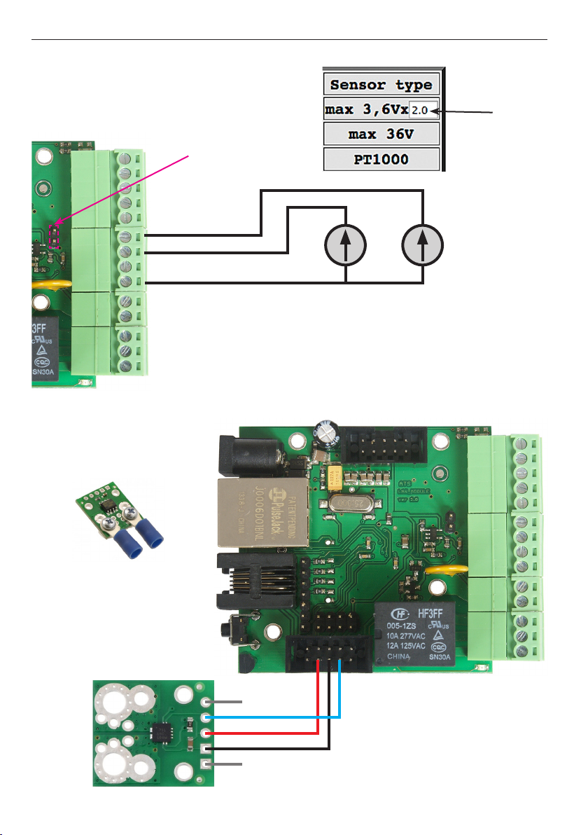
SENSORS CONNECT
1. Voltage measurement
jumper
INP1
INP2
GND
Measure voltage:
0 ÷ 36 V DC
multiplier
Measure voltage:
0 ÷ 7.2 V DC
(multiplier 2.0) or
0 ÷ 3.6 V DC
after using jumper
and adjusting the
multiplier (multi-
plier 1.0)
2. Connecting the current sensor ACS711ex
Recommended
installation of cables
IP+
FAU LT
OUT – Pin7
Vcc – Pin3
GND – Pin5
GND
IP–
7
www.tinycontrol.eu
ID C10-1
IDC10-2
Page 8
manual LAN Controller V2.0 – Firmware: HOME v. 3.13 and ISP v. 2.09 – LANKONT-002
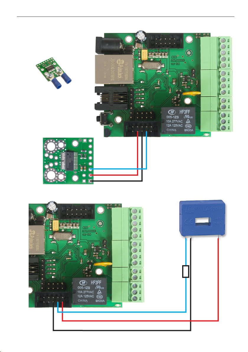
3. Connecting the current sensor ACS709
ID C10-1
Recommended
installation of cables
IDC10-2
IP+
OUT – Pin7
IP–
Vcc – Pin3
GND – Pin5
4. Connecting the sensor LA100-P
ID C10-1
IDC10-2
www.tinycontrol.eu
– +
72 Ω
INP4
Vcc – Pin9 (12V)
GND – Pin5
8
Page 9

manual LAN Controller V2.0 – Firmware: HOME v. 3.13 and ISP v. 2.09 – LANKONT-002
5. Voltage connections to INP5 using a resistive divider
ID C10-1
U
1
R
1
U
U
1
U
2
R1 + R
+ U2
1
=
R
2
R
2
R
1
R
2
U
2
U
U = U
U
2
2
=
IDC10-2
EXAMPLE
U – Input voltage for the measurement
U
– the voltage at the input INP5 (max. 3.6 V)
2
for the measurement of up to 36 V, use the divider:
R1 = 9 kΩ, R2 = 1 kΩ,
for the measurement of up to 360 V, use the divider:
R1 = 99 kΩ, R2 = 1 kΩ,
As a result of sharing multiplier enter: U / U
2
INP5 – Pin10
GND – Pin5
R
1
U
U
2
R
2
6. Set the sensor type INP4 and the value of the multiplier INP5
ACS = 0 – No Reading
ACS = 1.0 – 15A (ACS711 ex )
ACS = 2.0 – 30A (AC S7 11e x)
ACS = 3.0 – 75A (ACS709)
ACS = 4.0 – resistor 0,1Ω
ACS = 5.0 – LA100-P (through resistor 75Ω)
multiplier
9
www.tinycontrol.eu
Page 10
manual LAN Controller V2.0 – Firmware: HOME v. 3.13 and ISP v. 2.09 – LANKONT-002
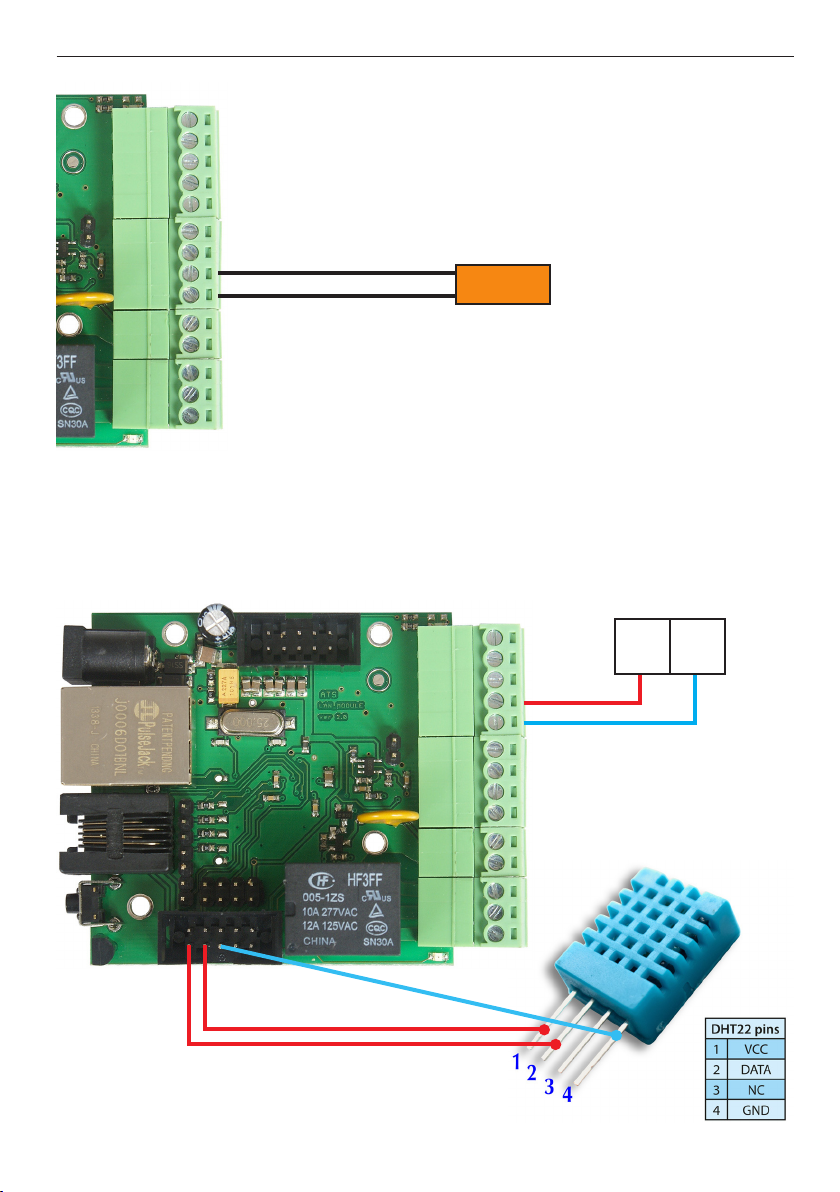
7. Temperature measurement
INP3
PT1000
GND
8. DHT22 sensor and pulse output from the counter (v. 3.13)
The maximum frequency of counting pulses is 10 pulses per 1 second.
output terminals
of the meter pulse energy
for dierent counters
ID C10-1
may dier markings
IDC10-2
10
www.tinycontrol.eu
+
20 21
–
Page 11
manual LAN Controller V2.0 – Firmware: HOME v. 3.13 and ISP v. 2.09 – LANKONT-002
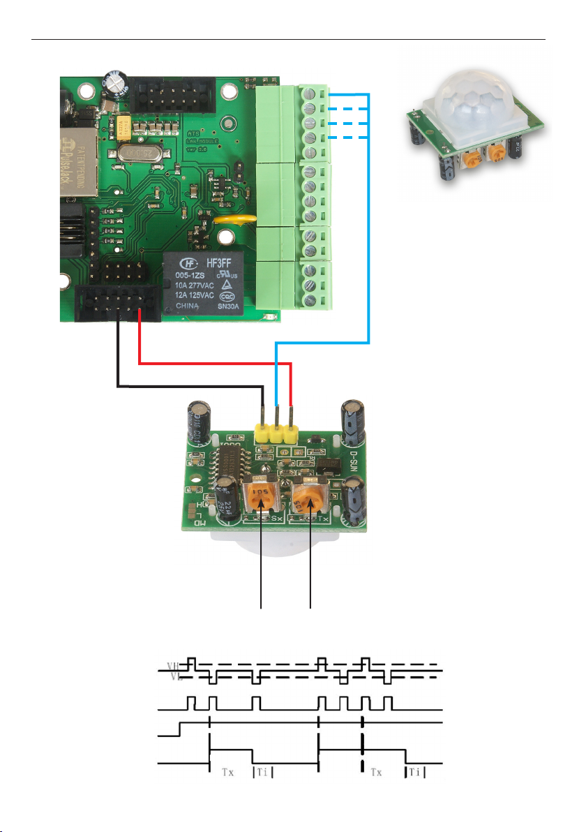
9. PIR motion sensor interface
ID C10-1
IDC10-2
Vcc – Pin9 (9÷24V)
GND – Pin5
delay setting after which
the loss of movement
can actuated output again
PIR
sensor
Detected
motion
Jumper
setting
Output
INP1D÷INP4D
setup
operation time
low state 0~0,8V
high state 0,8V~20V
11
www.tinycontrol.eu
Page 12
manual LAN Controller V2.0 – Firmware: HOME v. 3.13 and ISP v. 2.09 – LANKONT-002
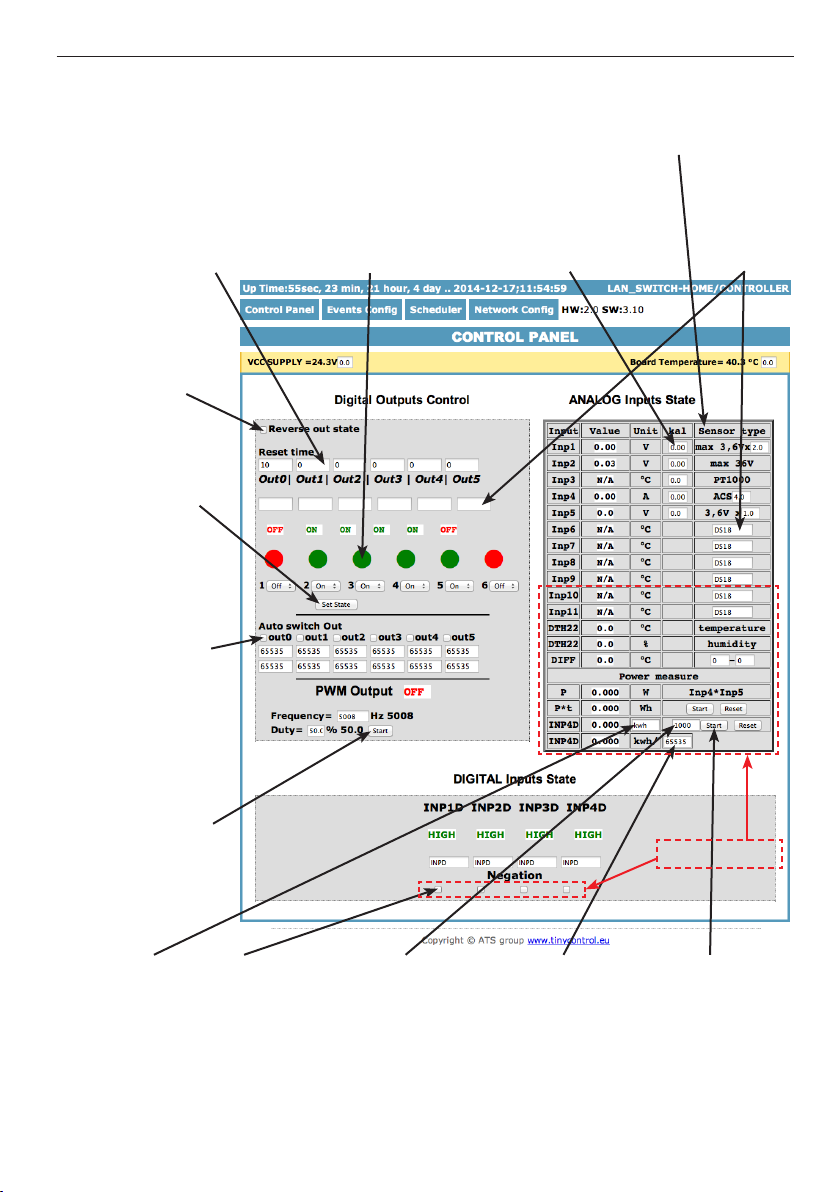
Management by WWW.
1. Control Panel
Reset time – „0” for normal
outputs work (ON/OFF) ,
for time > 0 output change
state and return to state before after the specied time
in seconds (max 65534).
Change outputs
state display
Set State
All output
simultaneously
according to
combo box
automatic socket
arming at xed
time (two panes:
one - time arming,
second - break
time)
click cause
change relay
state on opposite
(OUT0 relay on
board)
Select the type of sensor
connected to the corre-
sponding input
Value of calibration
- adds to or subtracts
the desired value
Any text
description,
max 8 chars
Run PWM genera-
tor (when chan-
ging frequency or
ll does not need
to turn o the
generator)
Any description
of the measured
physical
quantity,
such as kWh,
L/min, etc.
(only v. 3.13)
Negation for
digital input
for Even Con-
(only v. 3.13)
g tripping
Divider pulse counter
- for example as ours
energy meter sends 1000
pulses per 1 kWh is enter
1000, as it sends 1600
pulses enter 1600, etc.
(only v. 3.13)
12
www.tinycontrol.eu
Time avera-
ged over
a values
of power
measurement
(in minutes)
(only v. 3.13)
only v. 3.13
Run Power
measure from
INP3 (voltage)
and INP5 (current)
(only v. 3.13)
Page 13
manual LAN Controller V2.0 – Firmware: HOME v. 3.13 and ISP v. 2.09 – LANKONT-002
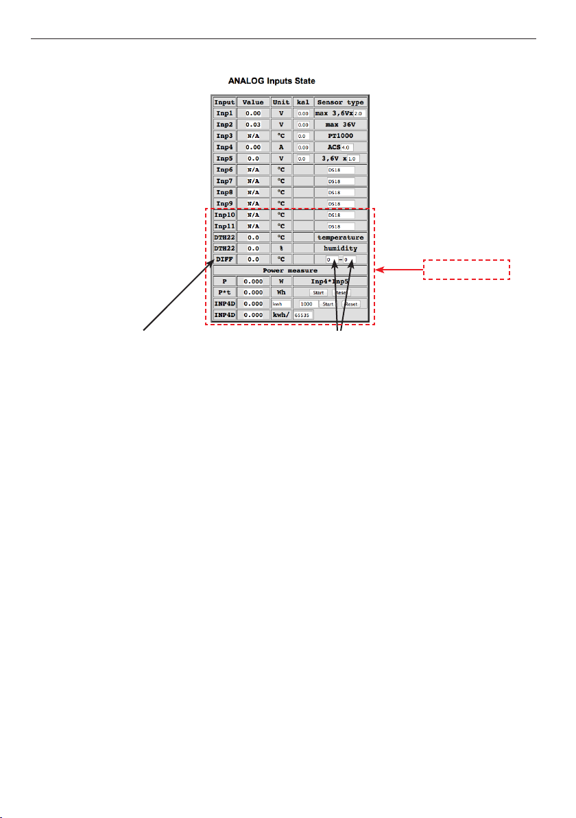
1.1 ANALOG Inputs State (Control Panel)
only v. 3.13
Added measurement of temperature dierence with the selected temperature sensors
- the value of DIFF in the table.
(enter the numbers of temperature sensors in
the boxes - in the „DIFF” shows the dierence
of their values).
The numbers of sensors:
0 – inserts 0 value, (then receive a value
from one sensor, positive or negative,
depending on which window (rst or
second) enter zero, and what temp. (+ or –)
indicates a sensor)
3 – pt1000
4 – temp
6 – inp6 (DS18B20)
7 – inp7 (DS18B20)
8 – inp8 (DS18B20)
9 – inp9 (DS18B20)
10 – inp10 (DS18B20)
11 – inp11 (DS18B20)
12 – DTH22 temperature
NOTE: The calculation of the value of DIFF is:
[value (+ or –) temp. sensor in field 1] – [value (+ or –) temp. sensor in field 2] = DIFF
Examples:
[+25 °C] – [+5 °C] = +20 °C [+5 °C] – [+25 °C] = –20 °C
[+25 °C] – [–5 °C] = +30 °C [+5 °C] – [–25 °C] = +30 °C
[–25 °C] – [+5 °C] = –30 °C [–5 °C] – [+25 °C] = –30 °C
[–25 °C] – [–5 °C] = –20 °C [–5 °C] – [–25 °C] = +20 °C
[no sensor (typed 0)] – [+10 °C ] = –10 °C
[no sensor (typed 0)] – [–10 °C] = +10 °C
[+10 °C] – [no sensor (typed 0)] = +10 °C
[–10 °C] – [no sensor (typed 0)] = –10 °C
13
www.tinycontrol.eu
Page 14
manual LAN Controller V2.0 – Firmware: HOME v. 3.13 and ISP v. 2.09 – LANKONT-002
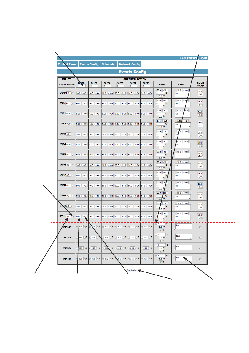
2. Events Cong
Delay of set outputs
after occur events,
in seconds max 65535
inclusion
of an input
If checked it responds
to a change of state,
otherwise no reaction (o)
The hysteresis
value for
a given input.
After exceeding
a preset value
upwards will be:
the inclusion
of an exit /
PWM generator /
send e-mail /
SNMP Trap
After crossing
the setpoint down
will be:
the inclusion
of an exit /
PWM generator /
send e-mail /
SNMP Trap
14
www.tinycontrol.eu
Save setings
(ON/OFF
input
you don’t
must save)
tylko
v. 3.13
tylko
v. 2.09
Email text taht
will be send if
events occurance,
max amount char
is 79. Chars „=”
and „&” are not
allowed
Page 15
manual LAN Controller V2.0 – Firmware: HOME v. 3.13 and ISP v. 2.09 – LANKONT-002
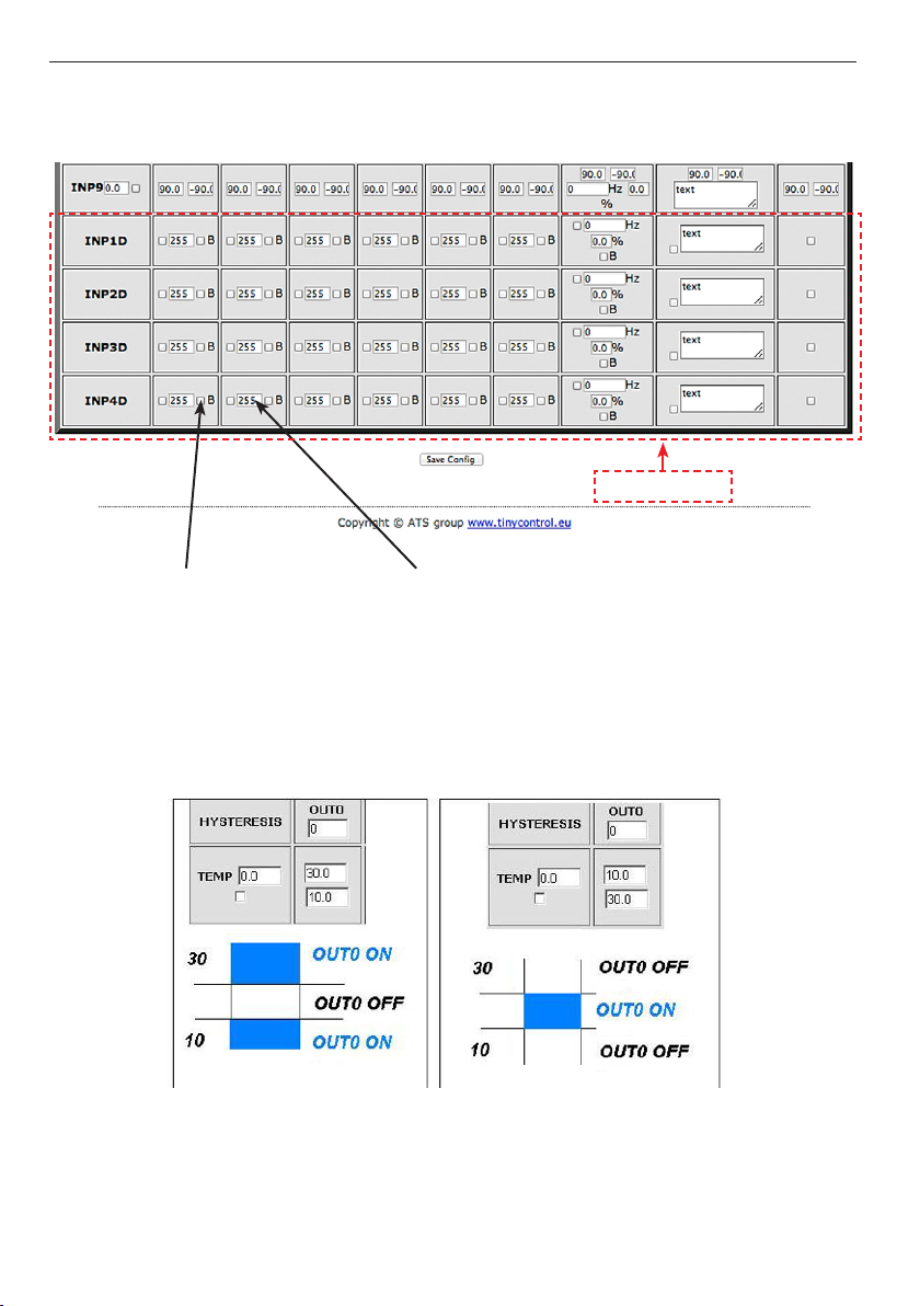
For logical input INP1D ÷ INP4D, e-mail and SNMP Trap notication are send when input level change from 1 to 0 or 0 to 1, additional to email text (at end) will be add value
1 or 0 mark actual input state.
tylko v. 2.09
Bistable operation input
- the rst change at INPD
to turn on output, the
second amendment to
disable output
If a value greater than 0,
is at work bistable output
is automatically switched
o after this time,
max 255 seconds
Functional Description Event Table
With this change, you can exibly dene thresholds and intervals in which such slot is to
be enabled / disabled.
If you have the proper checks the condition of a number of sensors is to force the state
OUTX outputs and setting the PWM generator to be that was last registered event.
15
www.tinycontrol.eu
Page 16
manual LAN Controller V2.0 – Firmware: HOME v. 3.13 and ISP v. 2.09 – LANKONT-002
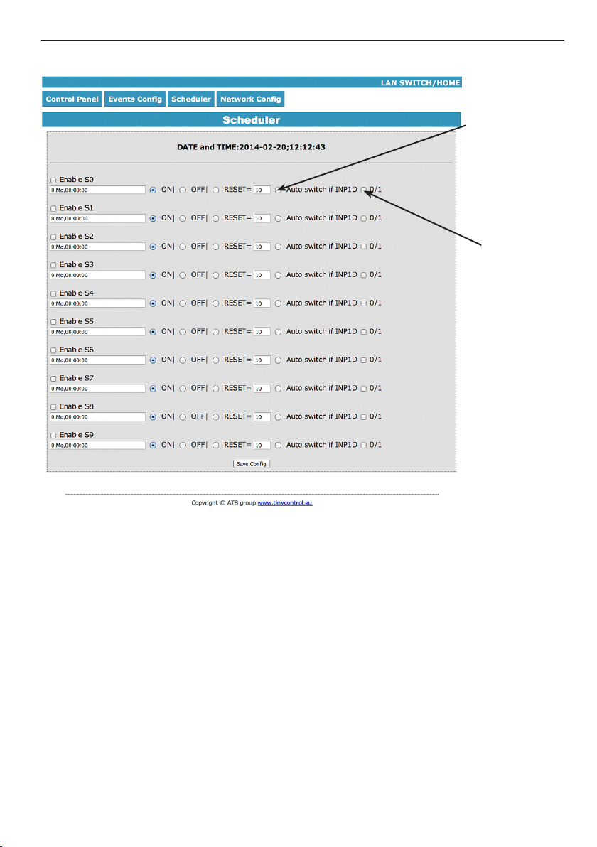
3. Scheduler
Allows you to
block actions
of Scheduler,
if you change
the input state
INP1D
allows you
to choose which
state INP1D
turn on
the lock
Format: number output (from 0 to 4),day1,day2,day3,day4,day5,day6, xx:xx:xx(time)
Week Day: Mo - Monday, Tu- Tuesday, We - Wednesday, Th - Thursday, Fi - Friday, Sa - Sa-
turday, Su - Sunday, ## - all week day. Letter size is important.
Example:
0,Mo,12:23:00 - sets out0 every Monday at 12:23:00
1,Sa;Fi,Mo,23:22:03 - sets out1 every Saturday, Friday and Monday at 23:22:03
1,Sa;Fi,Mo,Tu,Su,Th,23:22:03 - sets out1 every Saturday, Friday, Monday, Tuesday, Sunday
and Thursday at 23:22:03
0,##,12:01:30 - sets out0 every week day at 12:01:30
The eect of this may be the inclusion of a relay, switched o or reset (turn on and o) for
a limited period in seconds. (max 65535).
16
www.tinycontrol.eu
Page 17
manual LAN Controller V2.0 – Firmware: HOME v. 3.13 and ISP v. 2.09 – LANKONT-002
NOTE:
Some servers (eg. Google) require authentication outgoing mail.
Unfortunately, our device does not provide this functionality.
To send e-mail messages, select the servers that do not require it.
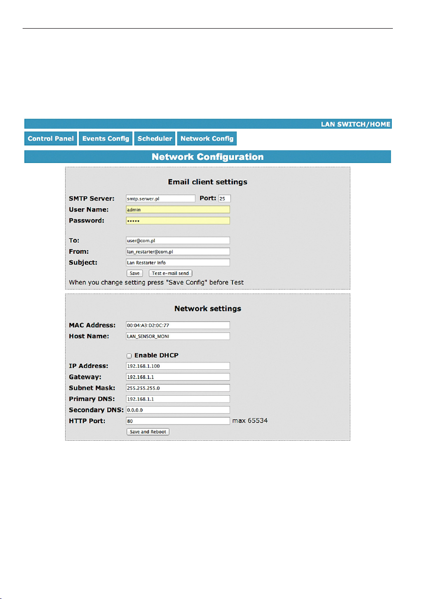
4. Network Conguration
e-mail client settings parameter.
After changing the
settings in order to
test the customer -
should be save your
settings - the „Save
Cong” button.
17
www.tinycontrol.eu
Page 18
manual LAN Controller V2.0 – Firmware: HOME v. 3.13 and ISP v. 2.09 – LANKONT-002
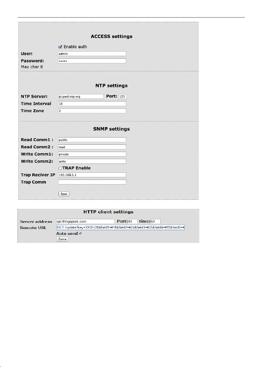
HTTP client settings - this is http client conguration.
The user name
and password
to access the
module.
You can disable
authorization.
NTP server set-
tings.
Time Interval -
the interval in
minutes between synchroniza-
tions.
Fields communi-
ty (password) for
SNMP, must be
the same in your
queries in order
to LK replied.
TRAP Enable –
enabled send
TRAP by SNMP.
This tool can easily send at specied intervals (time) value of the input or output states
on a remote server. As an example will use a free server https://www.thingspeak.com,
which allows you to show data in graphs in the timeline. To the contents of the command
to add value I/O, use the „#” and enter the number (a list of numbers p. 20).
Said sample server requires in turn give the command „GET /update?Key=” then the key
to our account (Write API key. Then, in turn attach a data eld &eld=#xx where xx is the
two-digit number of I/O, for example. „&Field=#05”
(NOTE! Record must be double digit, as we enter „5” to write „05”. If you need to send
data from several sensors are elds „eld” separated by commas.
Maximum server name is 31 characters, the maximum string RemouteURL is 127 characters. The time window, type frequency in seconds with which data will be sent to the server. In the following example, and for normal queries between „GET” and „/” is a space.
Selecting Auto send and save this state will activate the function.
18
www.tinycontrol.eu
Page 19
manual LAN Controller V2.0 – Firmware: HOME v. 3.13 and ISP v. 2.09 – LANKONT-002
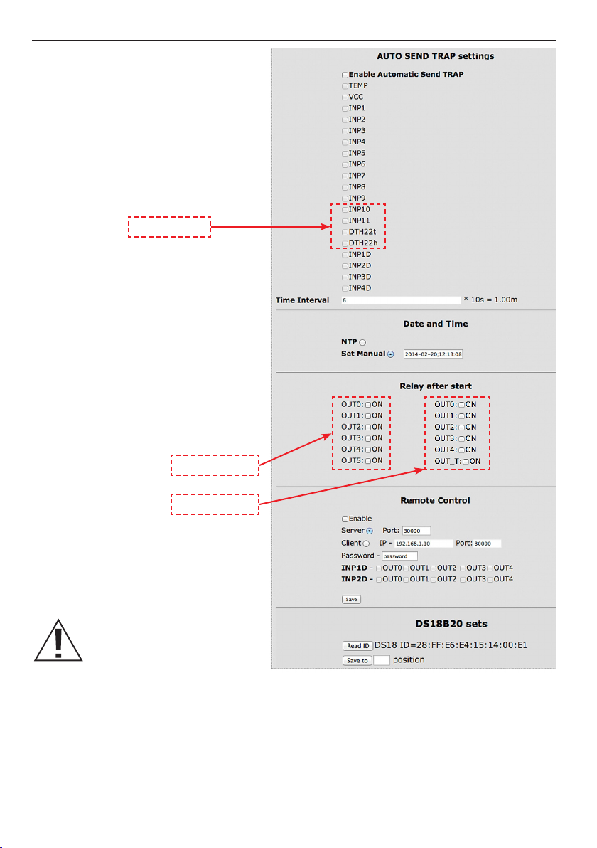
Enable Automatic Send TRAP – enable
automatic send TRAP by SNMP (above
TRAP Enable must be enable)
only v. 3.13
Time Interval (max value 10555) – period
to send TRAP from given INPUT,
accuracy 10 s
Time is set individually or with an NTP
server. When set manually each time you
reboot the machine need to set the time.
Output status when you turn on
or reboot the LAN Controller
only v. 3.13
only v. 2.09
Assigning an item number
for the currently connected
sensor DS18B20.
1. Connect chosen sensor (others should be removed), 2. Refresh the button „Read ID”, (if it does
not appear ID, reset Lan Controller), 3. Enter the position number and press „Save to” button.
The read ID number will be assigned to the desired position, where „1” corresponds to INP6,
„2” is INP7 ... and „6” is INP11.
To add additional sensors, proceed as described above CONNECTED WITH ONLY ONE,
CURRENTLY added SENSOR.
If you want to remove the assignment, refresh the „Read ID” without sensor (so that the eld
was empt) and memorize the redundant item number („Save to”).
19
www.tinycontrol.eu
Page 20
manual LAN Controller V2.0 – Firmware: HOME v. 3.13 and ISP v. 2.09 – LANKONT-002
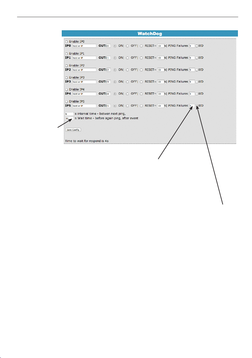
5. Watchdog (only v. 2.09)
(max 65535s).
Time to respond is 4 seconds,
after this time if no response
one PING failure is counting.
Then if it happen, during waiting for next respond PINGs to
other IP addresses are not realised. It can stretch watchdog
time to other IP addresses.
Amount PING failures, after
this one of three events will be
happen: set (ON) output, set
(OFF) output reset (ON/OFF)
output on denite time (max
65535s).
Selecting this option forces the watchdog
o when in the Event Table occur o / on
the socket.
Upon his return to the previous state out-
put watchdog is started automatically.
20
www.tinycontrol.eu
Page 21

manual LAN Controller V2.0 – Firmware: HOME v. 3.13 and ISP v. 2.09 – LANKONT-002
Remote Control - working as a server (receiving packets and enables / disables the corresponding output) or client (send packets to the server status change to INP1D or INP2D).
LK working as a server can be actuated from any number of clients, provided it is set to the
same password. Change in INP1D or INP2D low can switch outputs selected in the state of
„ON”, return to enter the high state output switches to „OFF”.
I/O TABLE NUMBERS (soft 3.XX)
#dene OUT0 (5)
#dene OUT1 (6)
#dene OUT2 (7)
#dene OUT3 (8)
#dene OUT4 (9)
#dene OUT5 (10)
#dene TEMP (11)
#dene VCC (12)
#dene INP1 (13)
#dene INP2 (14)
#dene INP3 (15)
#dene INP4 (16)
#dene INP5 (17)
#dene INP6 (18)
#dene INP7 (19)
#dene INP8 (20)
#dene INP9 (21)
#dene INP10 (22)
#dene INP11 (23)
#dene DTH22_1 (24)
#dene DTH22_2 (25)
#dene DIFT (26)
#dene I3XI5 (30)
#dene PXT (31)
#dene PINP4D (32)
#dene PINP4D_24H (33)
#dene INP1D (41)
#dene INP2D (42)
#dene INP3D (43)
#dene INP4D (44)
www.tinycontrol.eu
I/O TABLE NUMBERS (soft 2.XX)
#dene OUT0 (5)
#dene OUT1 (6)
#dene OUT2 (7)
#dene OUT3 (8)
#dene OUT4 (9)
#dene OUT5 (10)
#dene TEMP (11)
#dene VCC (12)
#dene INP1 (13)
#dene INP2 (14)
#dene INP3 (15)
#dene INP4 (16)
#dene INP5 (17)
#dene INP6 (18)
#dene INP7 (19)
#dene INP8 (20)
#dene INP9 (21)
#dene INP10 (22)
21
Page 22

manual LAN Controller V2.0 – Firmware: HOME v. 3.13 and ISP v. 2.09 – LANKONT-002
Reading XML data
Enter the IP address and the page name eg 192.168.1.100/st0.xml
The values of the sensors should be divided by 10
Control Panel:
- Dynamic data - st0.xml
- Static data - st2.xml
Events Cong: s.xml
Scheduler: sch.xml
Network Cong: board.xml
Working time: s_time.xml using the Timezone
Switching sockets http request
You can arm / switch set out without clicking on the buttons in the control panel, making
use of the following commands :
IP/outs.cgi?out=xxxxx – switches set the output to the opposite of the current
IP/outs.cgi?outx=x – disable or enable a specic output
when password authentication is enabled , the command of the following form :
user:password@IP/outs.cgi?out=xxxxx
user:password@IP/outs.cgi?outx=x
Examples:
192.168.1.10 0/outs.cgi?out=0 – changes the output state to the opposite out0
192.168.1.10 0/outs.cgi?out=2 – out2 output changes state to the opposite
192.168.1.10 0/outs.cgi?out=02 – changes the output state out0 and out2
to the opposite
192.168.1.10 0/outs.cgi?out=01234 – changes the state of the outputs of out0 to out4
the opposite
192.168.1.10 0/outs.cgi?out0=0 – turns out out0 ( ON state )
192.168.1.10 0/outs.cgi?out0=1 – turns out out0 ( OFF )
192.168.1.10 0/outs.cgi?out1=0 – turns out out1 ( ON state )
192.168.1.10 0/outs.cgi?out1=1 – turns out out1 ( OFF )
192.168.1.10 0/outs.cgi?out4=0 – turns out out4 ( ON state )
192.168.1.10 0/outs.cgi?out4=1 – turns out out4 ( OFF )
22
www.tinycontrol.eu
Page 23

manual LAN Controller V2.0 – Firmware: HOME v. 3.13 and ISP v. 2.09 – LANKONT-002
Managing PWM by HTTP GET:
change frequency
ht tp://192.168 .1.100/ind.cgi?pwmf=9777 –
change duty:
ht tp://192.168 .1.100/ind.cgi?pwmd= 855 – setup duty to 85,5%
ht tp://192.168 .1.100/ind.cgi?pwm=1 – activates pwm output
ht tp://192.168 .1.100/ind.cgi?pwm=0 – o pwm output
ht tp://192.168 .1.100/ind.cgi?pwmd=990 – setup duty cycle pwm to 99%
ht tp://192.168 .1.100/ind.cgi?pwmf =50 00 – setup 5 kHz frequency has all pwm outputs,
that is, PWM, PWM1, PWM2, PWM3
ht tp://192.168 .1.100/ind.cgi?pwm1=1 – activates pwm1 output
ht tp://192.168 .1.100/ind.cgi?pwm1=0 – o pwm1 output
ht tp://192.168 .1.100/ind.cgi?pwm2=1 – activates pwm2 output
ht tp://192.168 .1.100/ind.cgi?pwm2=0 – o pwm2 output
ht tp://192.168 .1.100/ind.cgi?pwm3=1 – activates pwm3 output
ht tp://192.168 .1.100/ind.cgi?pwm3= 0 – o pwm3 output
ht tp://192.168 .1.100/ind.cgi?pwmd1=500 – setup duty cycle pwm1 to 50%
ht tp://192.168 .1.100/ind.cgi?pwmd2=990 – setup duty cycle pwm2 to 99%
ht tp://192.168 .1.100/ind.cgi?pwmd3=100 – setup duty cycle pwm3 to 10%
:
setup frequency to
9777
An accurate description of all the settings by POST / GET
for Even Cong and the Scheduler is in a separate le
„POST / GET data description”
(downloadable from www.tinycontrol.eu)
23
www.tinycontrol.eu
Page 24

manual LAN Controller V2.0 – Firmware: HOME v. 3.13 and ISP v. 2.09 – LANKONT-002
NUMBERS OID for SNMP
#dene SYS_DESCR (99) // iso.3.6.1.2.1.1.1.0: READONLY ASCII_STRING.
#dene SYS_UP_TIME (97) // iso.3.6.1.2.1.1.3.0: READONLY TIME_TICKS.
#dene SYS_NAME (98) // iso.3.6.1.2.1.1.4.0: READWRITE ASCII_STRING.
#dene TRAP_RECEIVER_ID (1) // iso.3.6.1.4.1.17095.2.1.1.1.0: READWRITE BYTE.
#dene TRAP_RECEIVER_ENABLED (2) // iso.3.6.1.4.1.17095.2.1.1.2.0: READWRITE BYTE.
#dene TRAP_RECEIVER_IP (3) // iso.3.6.1.4.1.17095.2.1.1.3.0: READWRITE IP_ADDRESS.
#dene TRAP_COMMUNITY (4) // iso.3.6.1.4.1.17095.2.1.1.4.0: READWRITE ASCII_STRING.
#dene OUT0 (5) // iso.3.6.1.4.1.17095.3.1.0: READWRITE BYTE.
#dene OUT1 (6) // iso.3.6.1.4.1.17095.3.2.0: READWRITE BYTE.
#dene OUT2 (7) // iso.3.6.1.4.1.17095.3.3.0: READWRITE BYTE.
#dene OUT3 (8) // iso.3.6.1.4.1.17095.3.4.0: READWRITE BYTE.
#dene OUT4 (9) // iso.3.6.1.4.1.17095.3.5.0: READWRITE BYTE.
#dene ALL (90) // iso.3.6.1.4.1.17095.3.100.0: READONLY OCTET_STRING.
#dene TEMP (10) // iso.3.6.1.4.1.17095.4.1.0: READONLY ASCII_STRING.
#dene VCC (11) // iso.3.6.1.4.1.17095.4.2.0: READONLY ASCII_STRING.
#dene INP1 (12) // iso.3.6.1.4.1.17095.4.3.0: READONLY ASCII_STRING.
#dene INP2 (13) // iso.3.6.1.4.1.17095.4.4.0: READONLY ASCII_STRING.
#dene INP3 (14) // iso.3.6.1.4.1.17095.4.5.0: READONLY ASCII_STRING.
#dene INP4 (15) // iso.3.6.1.4.1.17095.4.6.0: READONLY ASCII_STRING.
#dene INP5 (16) // iso.3.6.1.4.1.17095.4.7.0: READONLY ASCII_STRING.
#dene INP6 (17) // iso.3.6.1.4.1.17095.5.1.0: READONLY ASCII_STRING.
#dene INP7 (18) // iso.3.6.1.4.1.17095.5.2.0: READONLY ASCII_STRING.
#dene INP8 (19) // iso.3.6.1.4.1.17095.5.3.0: READONLY ASCII_STRING.
#dene INP9 (20) // iso.3.6.1.4.1.17095.5.4.0: READONLY ASCII_STRING.
#dene INP10 (21) // iso.3.6.1.4.1.17095.5.5.0: READONLY ASCII_STRING.
#dene INP11 (22) // iso.3.6.1.4.1.17095.5.6.0: READONLY ASCII_STRING.
#dene DTH22_1 (23) // iso.3.6.1.4.1.17095.6.1.0: READONLY ASCII_STRING.
#dene DTH22_2 (24) // iso.3.6.1.4.1.17095.6.2.0: READONLY ASCII_STRING.
#dene I3XI5 (30) // iso.3.6.1.4.1.17095.7.1.0: READONLY ASCII_STRING.
#dene PXT (31) // iso.3.6.1.4.1.17095.7.2.0: READONLY ASCII_STRING.
#dene PINP4D (32) // iso.3.6.1.4.1.17095.7.3.0: READONLY ASCII_STRING.
#dene PINP4D_24H (33) // iso.3.6.1.4.1.17095.7.4.0: READONLY ASCII_STRING.
#d ene INP1D (41) // iso. 3.6.1.4.1.170 95.10.1. 0: RE ADON LY BY TE.
#dene INP2D (42) // iso.3.6.1.4.1.17095.10.2.0: READONLY BYTE.
#dene INP3D (43) // iso.3.6.1.4.1.17095.10.3.0: READONLY BYTE.
#dene INP4D (44) // iso.3.6.1.4.1.17095.10.4.0: READONLY BYTE.
24
www.tinycontrol.eu
Page 25
manual LAN Controller V2.0 – Firmware: HOME v. 3.13 and ISP v. 2.09 – LANKONT-002
Firmware Upgrade
In the event that there is a new version of the software or special version for application,
it is possible to load such software to the device. This can be done remotely over the network using TFTP.
You my upgrade rmware on two way:
1. By dedicate software LAN Controler Tools.exe (nd controler or put IP and click „Upgrade Firmware”).
2. By any TFTP client, description below.
Send rmware le by TFTP, you have 5 second (Green LED on RJ45 socket blink) to start
send rmware when modul run after reset (you my casus reset by click button „Save cong and Reboot” in Network conguration or „Reset” button on board or dedicate software „LAN Controler Tools”). If start transmision not happen that device start work normal.
If tftp transmision will start than wait about 90 second to nish upload rmware. After
upload device will be reset and start normal. If you want to upload upgrade le chose
„Save cong and Reboot” in Network conguration or power OFF and power ON device .
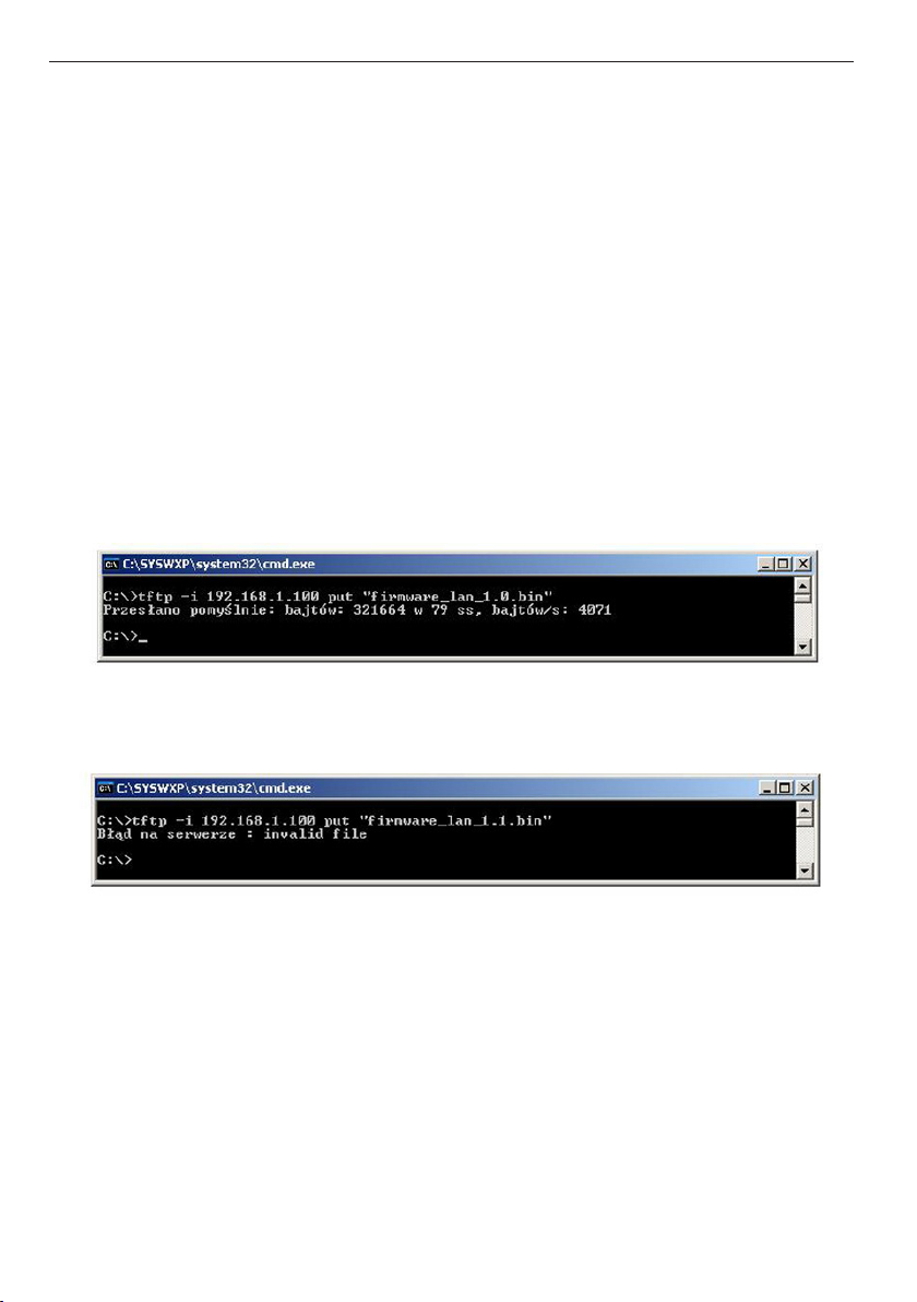
The le must be send in binary mode eg. In Windows XP tftp client
tftp –i 192.168.1.100 put „le_upgrade.bin”.
After successful loading, the device will reboot and will be ready to go.
If you try to send the wrong le get an error message „invalid le”
Contents of the instructions is regularly checked and if necessary corrected. If the observations errors or
inaccuracies, please contact us. It can not be ruled out that, despite best eorts, however, some discrepancies
arose. To get the latest version, please contact us or distributors.
Copying, duplication, reproduction whole or in part
without the consent of the owner is prohibited.
© Konsorcjum ATS Sp.J.
25
www.tinycontrol.eu
Page 26

manual LAN Controller V2.0 – Firmware: HOME v. 3.13 and ISP v. 2.09 – LANKONT-002
NOTES
26
www.tinycontrol.eu
Page 27

manual LAN Controller V2.0 – Firmware: HOME v. 3.13 and ISP v. 2.09 – LANKONT-002
NOTES
27
www.tinycontrol.eu
Page 28

Konsorcjum ATS Sp.J.
ul. Żeromskiego 75, 26–600 Radom, POLAND
tel./fax: +48 48 383 00 30, e-mail: [email protected]
www.tinycontrol.eu, www.ledats.pl, www.wirelesslan.pl, www.ats.pl
 Loading...