

Page 1

FZ200BS
Quick Guide
Page 2
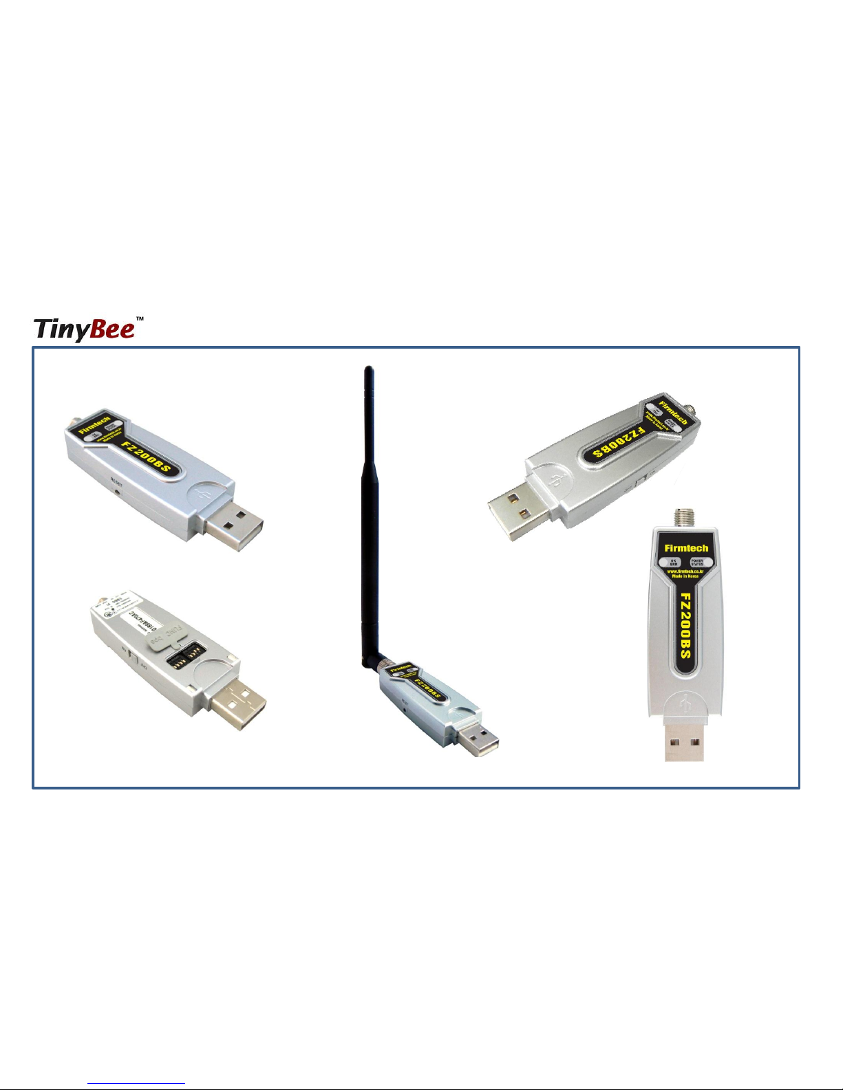
Features of FZ200BS
Page 3

< Features of Zigbee >
• It meets International Standard specifications with the aim of achieving Low power
consumption/Low cost/Low capacity
• It uses 2.4GHz ISM (Industrial, Scientific, Medical) Band which doesn’t require any
permission to use.
• It has 16 channels in 2.4GHz band
• Wireless transmission rate : 250Kbps
• It configures the ZigBee Network using Coordinator, Router and End Device
• By using ACK, whether the data is successfully transmitted can be assured.
• It can reset the route for data transmission in the ZigBee network by using the function of
data re-transmission
Page 4
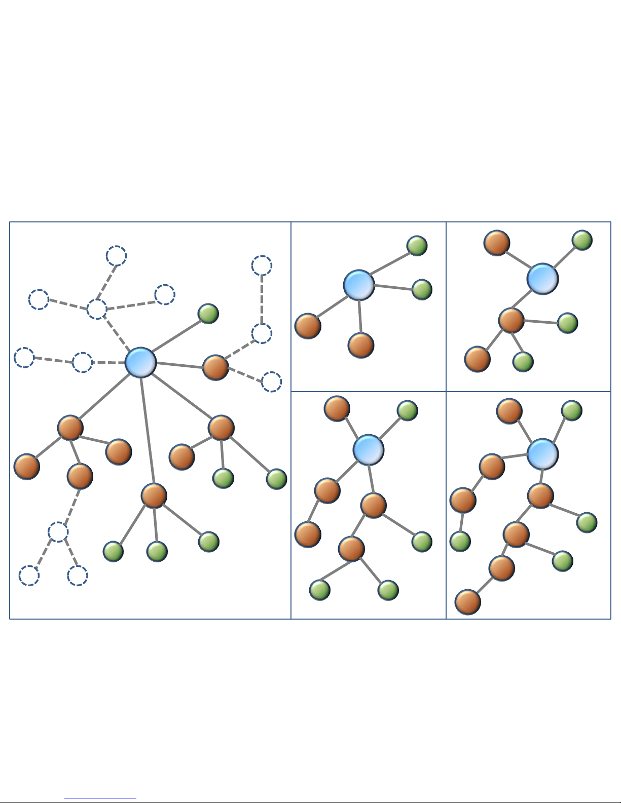
An Example of ZigBee Network configuration
router
end
router
router
router
router
router
router
router
end
end
end
end
end
end
router
router
end
end
Coordinator
Router
router
end
end
Coordinator
router
router
end
router
router
end
Coordinator
router
router
end
router
router
An example of ZigBee Network configuration
1 Depth ZigBee Network 2 Depth ZigBee Networks
router
end
router
end
router
router
end
end
Coordinator
router
end
3 Depth ZigBee Network 4 Depth ZigBee Network
coordinator
Page 5
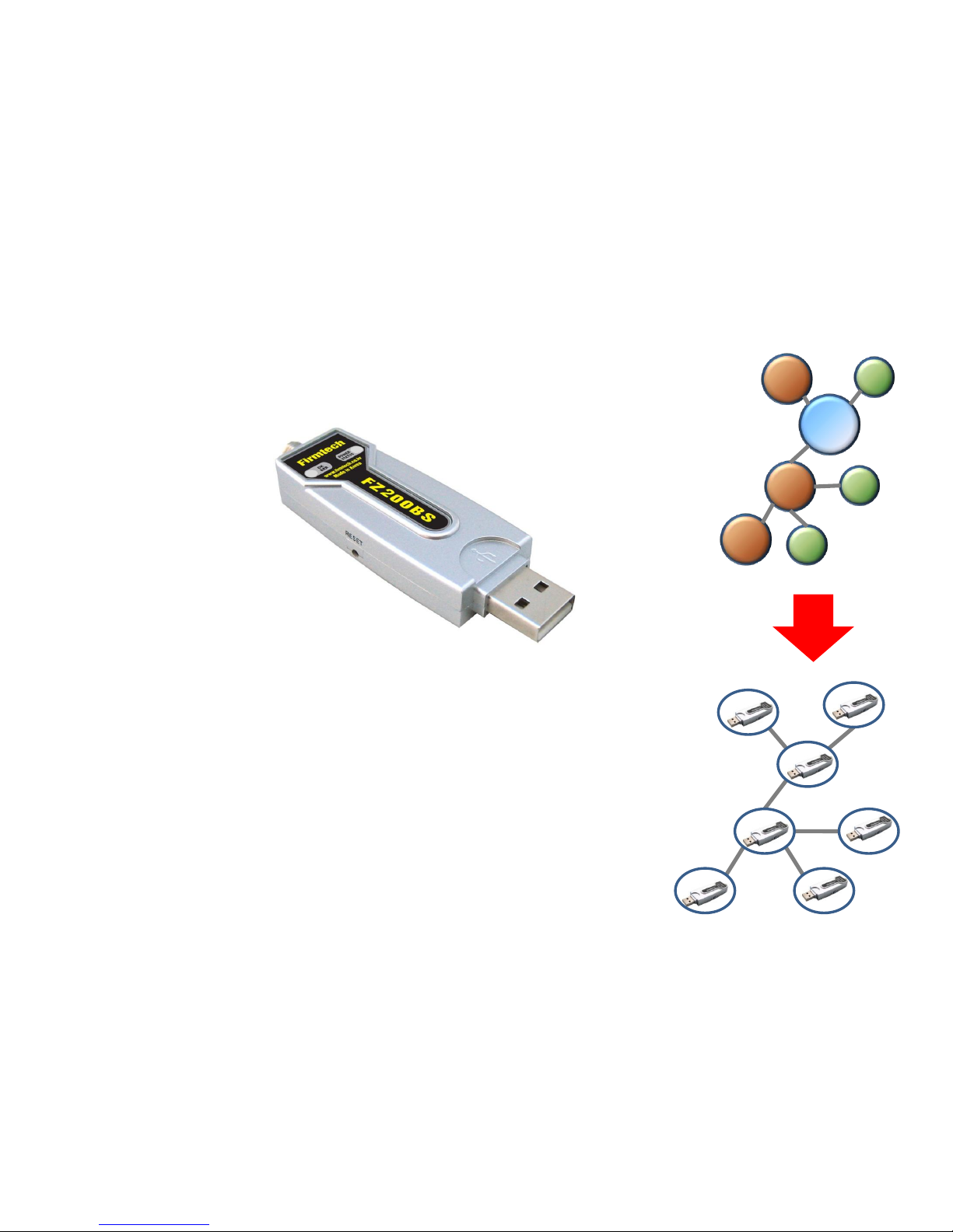
Features of FZ200BS
< FZ200BS >
• Can be freely set up as Coordinator, Router, or End device.
• Supports Mesh Network.
• Configured with USB Type.
• Controlled by AT Command
• Supports low power consumption mode in case of End Device. (Optional)
• Supports ACK function when data is transmitted.
• Provides function of data re-transmission and re-setting route.
Router
Router
End
End
Coordinator
Router
End
Page 6
C
R
E
R
R
E
E
Device Device
Device
SERIAL (RX/TX/GND)
Device
Device
PC
SERIAL (RX/TX/GND)
Router
Router
End
End
Coordinator
Router
End
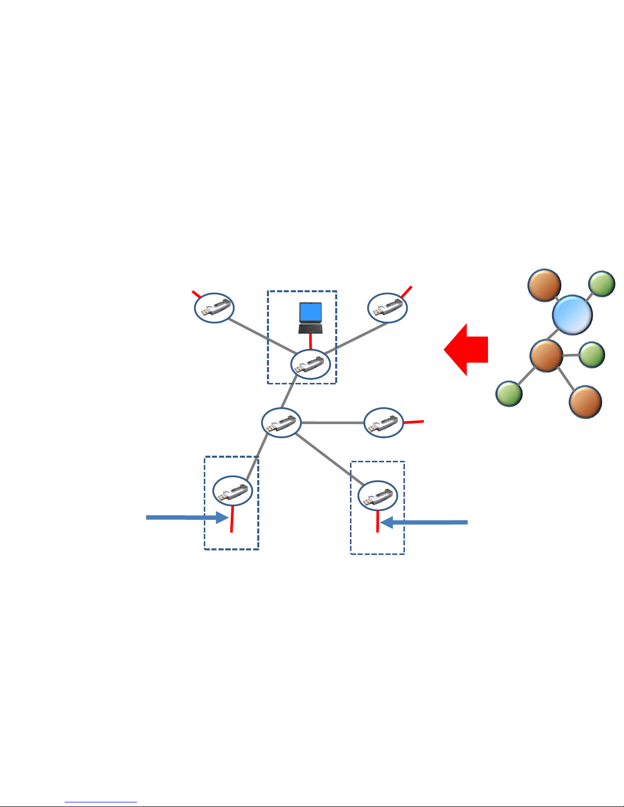
An example of a ZigBee Network Configuration using FZ200BS
Page 7

< “FZ200BS Quick Guide” >
(1) It’s Composed of 9 chapters in total.
(2) The “FZ200BS quick guide” proceeds in order.
(3) Thus, we recommend you to follow all chapters in order if you are
unfamiliar with FZ200BS.
(4) Please refer to the FZ200BS manual for further details.
Page 8

< List >
[0] component parts & Hardware installation to operate FZ200BS
[1] Setup of FZ200BS Driver
[2] Virtual Serial Port Matters to be attended to
[3] FZ200BS Operating & Reset
[4] FZ200BS set-up & Zigbee network construction
[5] FZ200BS Setting up Target Device
[6] Serial data transmission from Router to Coordinator
[7] Serial data transmission from End device to Router
[8] Serial data transmission from Coordinator to all the devices
Page 9

[0] Component parts
&
Hardware Installation to
operation FZ200BS
Page 10

1. FZ200BS ZigBee Network components
< Basic components 1 set>
• FZ200BS
• Antenna (4 dBi Gain)
(1) Basic components to operate FZ200BS (1 set)
Page 11
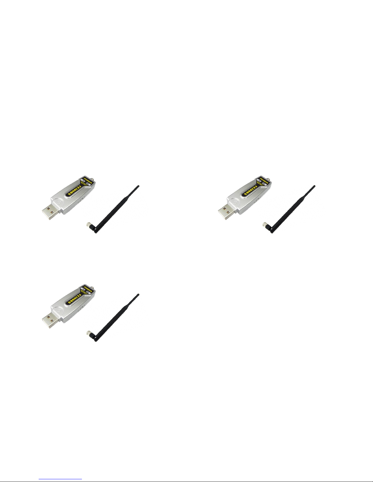
1 set for Coordinator set-up (Essential)
(2) ZigBee Network composition using 3 sets
1 set for Router set-up (Essential)
1 set for End device (Optional)
3 devices are used in “FZ200BS Quick
Guide” for explanation.
Page 12
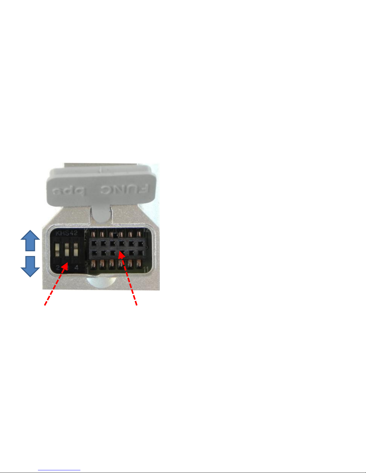
Dip Switch Interface Socket
ON
OFF
• Dip Switch Number#1 OFF
• Dip Switch Number#2 ON
• Dip Switch Number#3 OFF
• Dip Switch Number#4 OFF
• Select all the 3 FZ200BS are the
same way as above.
2. Check Dip-Switch before you install FZ200BS
For even more details of Dip-Switch and Interface
Socket, please refer to “FZx00_Appendix_3”.
Page 13
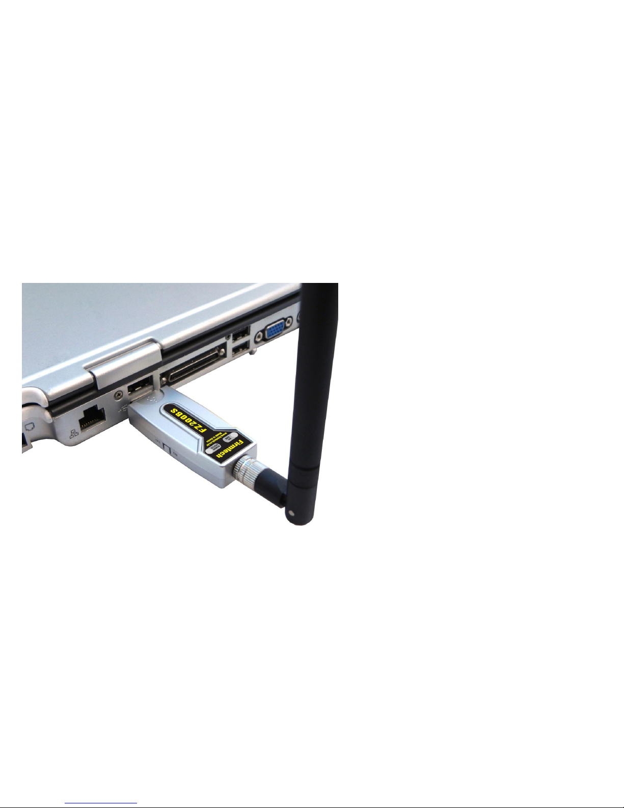
3. Product Installation
• Connect all 3 FZ200BS to the PC.
• “FZ200BS Quick Guide” explains
how to connect 1 PC to 3 FZ200BS
for convenience.
Page 14

[1] Setup of FZ200BS Driver
FZ200BS USB Driver and FB200AS USB Driver is same.
Page 15
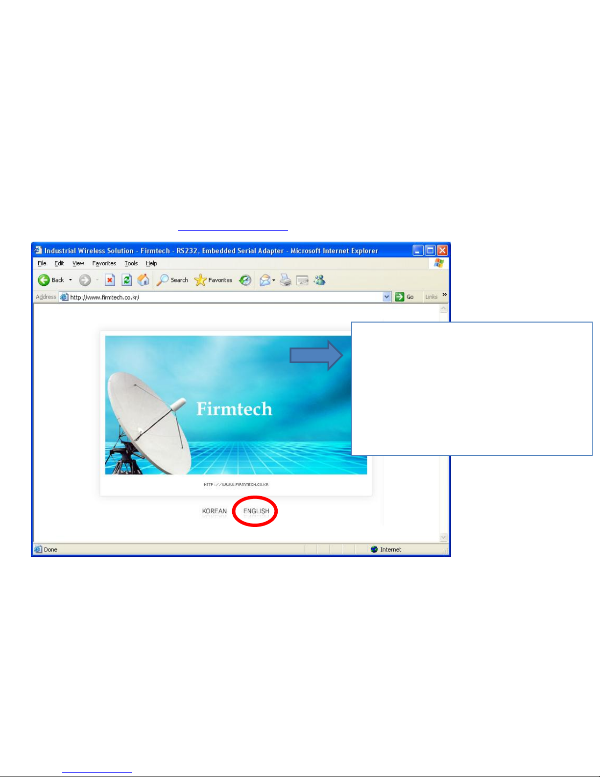
1. Download for FZ200BS Driver Installation
(1) Homepage Connection: www.firmtech.co.kr
Connect the homepage of firmtech to
download USB2Serial Driver for FZ200BS
usage.
Homepage Address: www.firmtech.co.kr.
Click “ENGLISH”.
Page 16

(2) Download Location Selection
Click "DOWNLOAD" on the homepage of
Firmtech.
Click "Utility & Source”.
Page 17
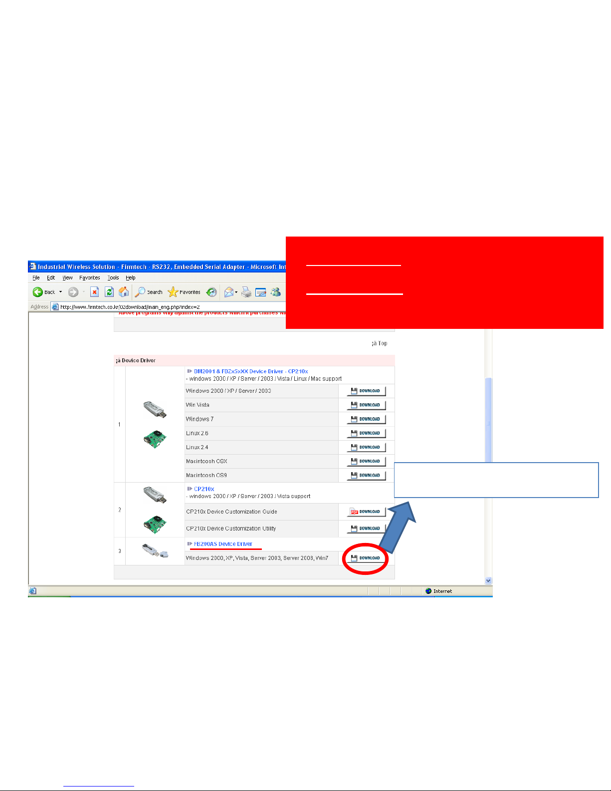
(3) “FZ200BS Device Driver” Download
Click "DOWNLOAD“ of FB200AS
device driver agenda.
“FZ200BS USB Driver” and
“FB200AS USB Driver” is
same.
Page 18
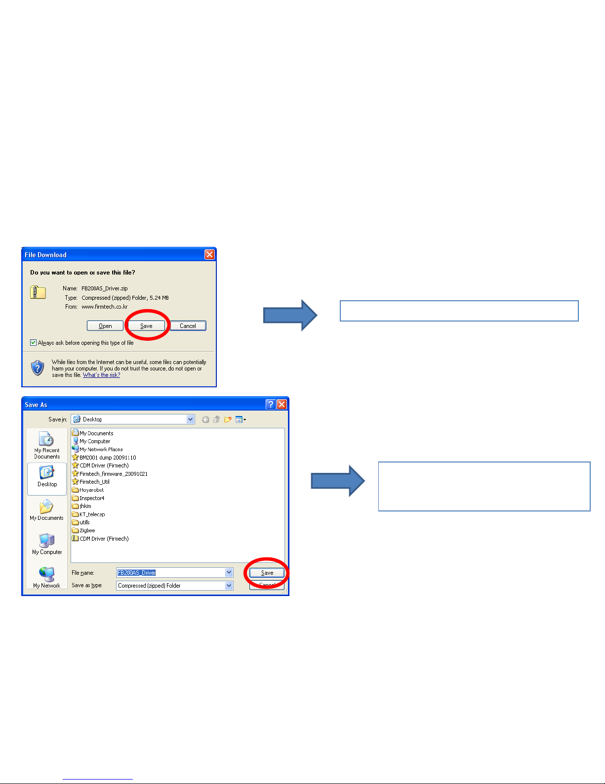
(4) File Download Window
Click "Save" in file download window.
Position saving location and click
"save".(assumption(left): save it in
Desktop on the computer).
Page 19
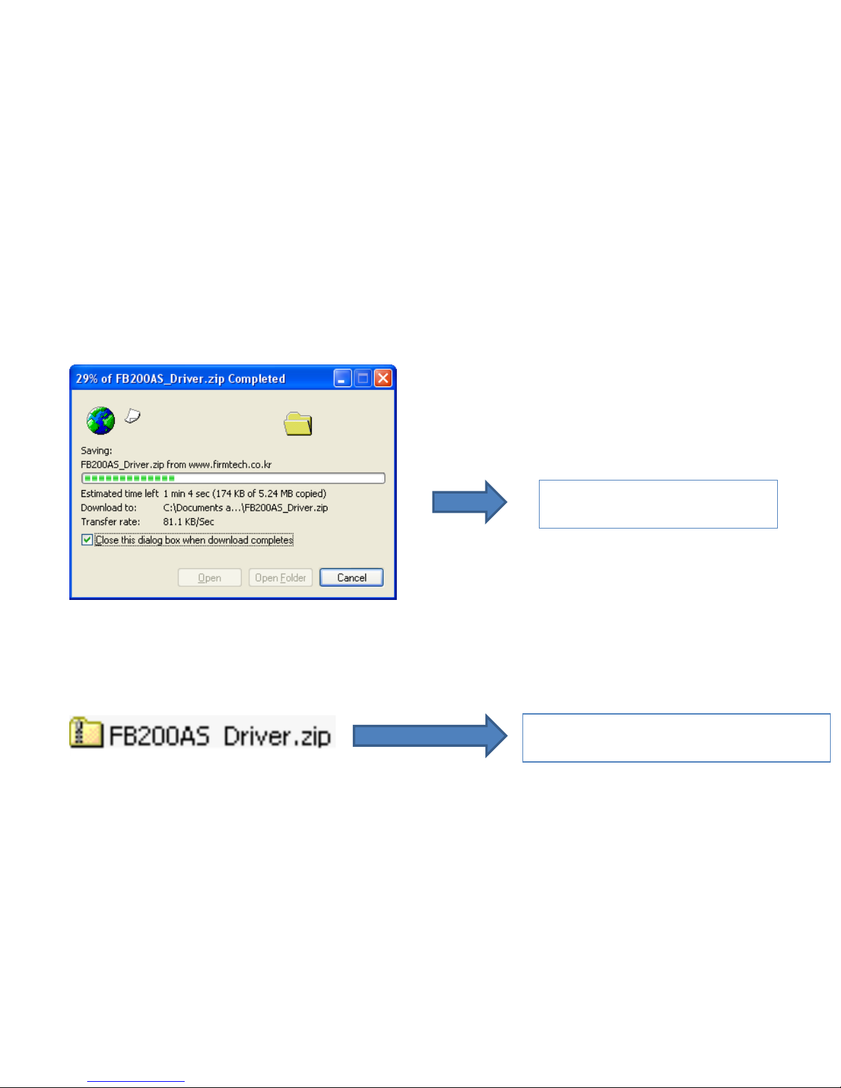
(5) Download Progress
Wait until the download is
completed.
"FB200AS_Driver.zip file is displayed
on the Desktop.
Page 20
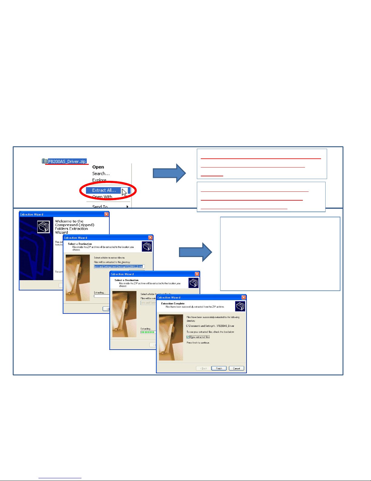
Decompressing program can be
different according to user's
environment.
Decompress a file by using a
file-decompressing program.
(assumption(left): Decompress it
in Desktop on the computer)
⑴
Decompress the FB200AS Driver.zip
file by clicking the right mouse
button
⑵
⑶
⑷
⑸
(1) Decompression
Basic assumption : A user makes
use of decompressing program
supported by Windows XP
2. Downloaded File Copy
Page 21
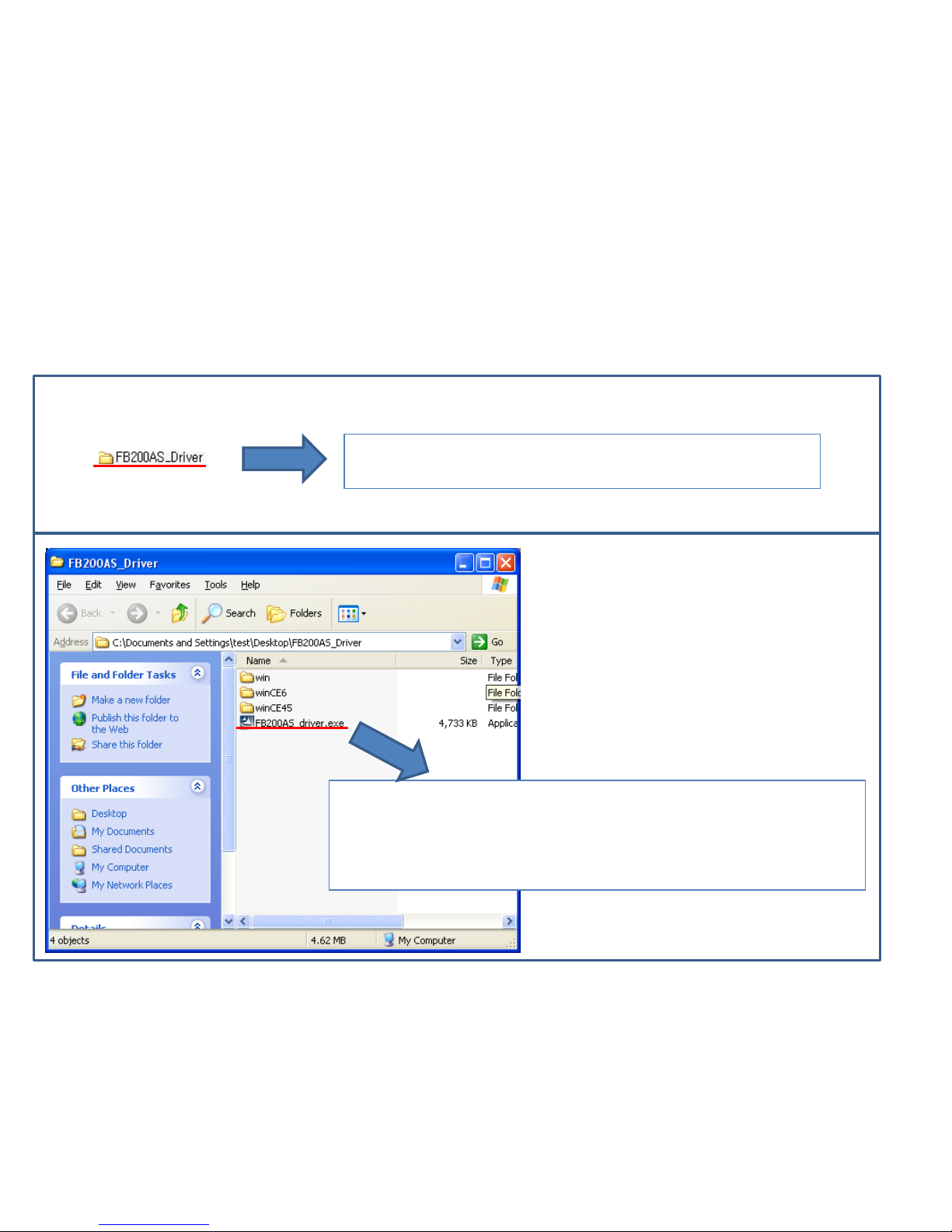
(2) A created file by decompression
⑴
⑵
"FB200AS_Driver" folder is created on Desktop by
decompressed file.
Doubleclick "FB200AS_driver.exe" out of the files of
"FB200AS_Driver"
That is, this process is being copied at “C:\Program Files
\FIRMTECH \FB200AS_Driver\” of user's computer.
Page 22
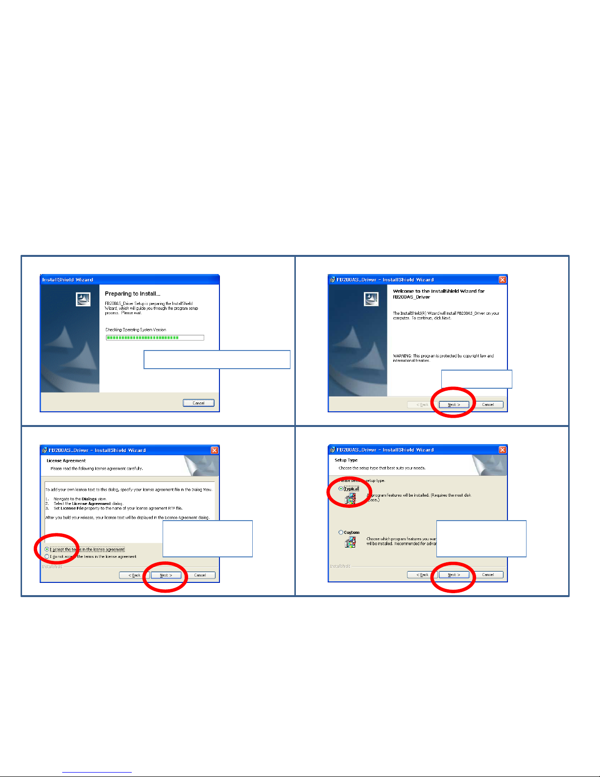
(3) Driver File Copy 1
⑴
⑵
⑶
⑷
Reset it for driver file copy.
Click “Next.”
Select "accept."
Click "Next."
Select "Typical."
Click "Next."
Page 23
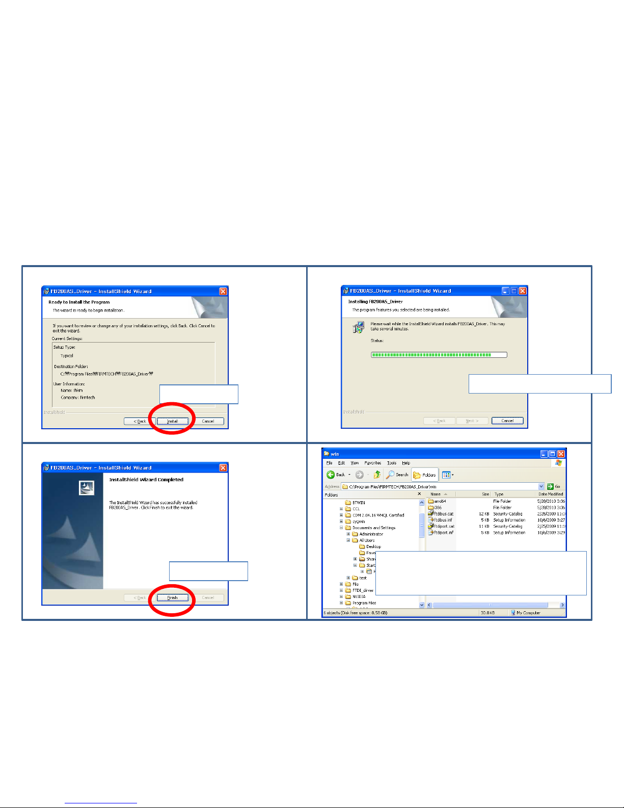
⑺
⑻
⑸
Click “Install”
⑹
File copy is being copied.
Click “Finish.”
Confirm the copy content at the folder
of “C:\Program Files \FIRMTECH
\FB200AS_Driver\win\.”
(4) Driver File Copy 2
Page 24
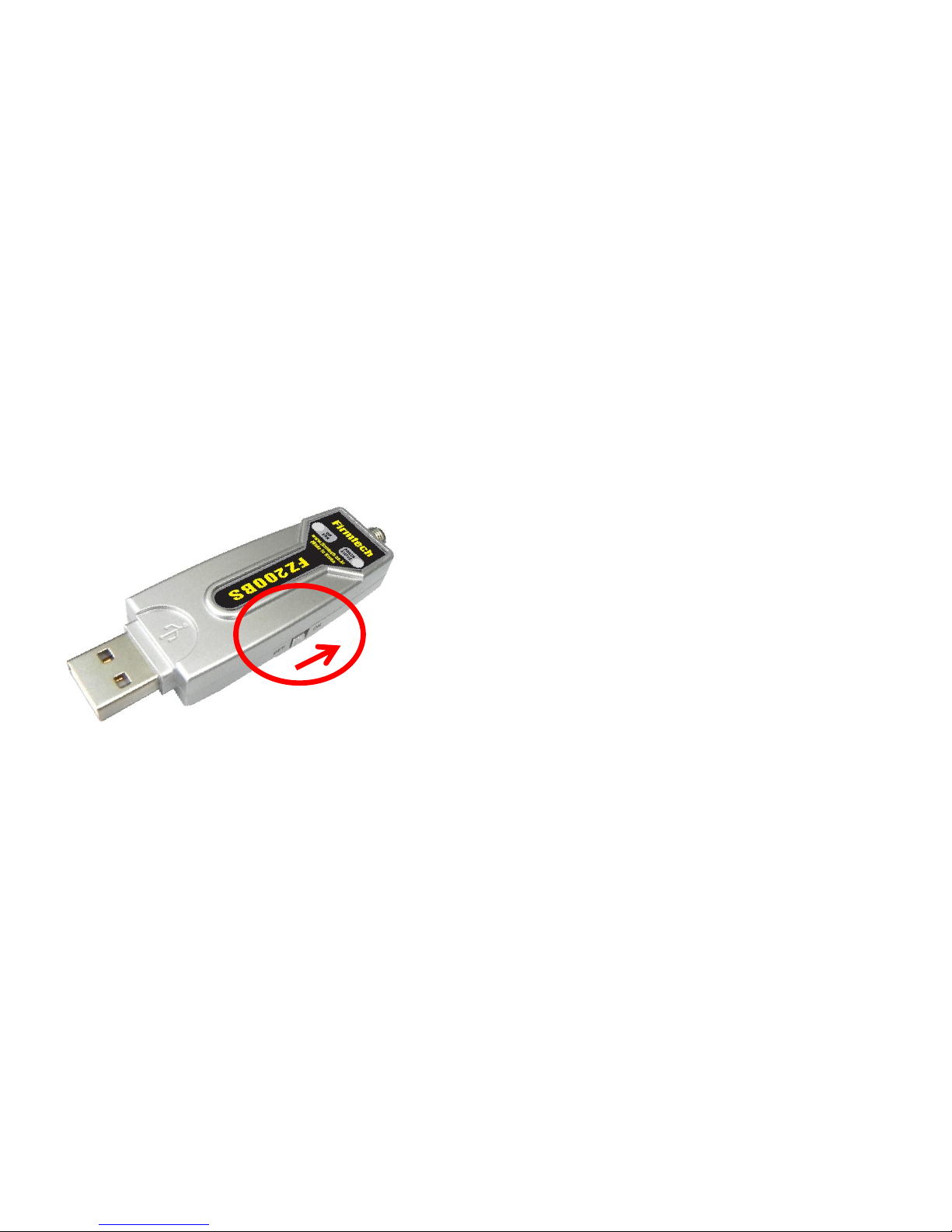
3. FZ200BS_Driver Installation Setup
(1) FZ200BS Power-Supply ON
• Install FZ200BS at a PC.
• Power Supply ON of FZ200BS.
Page 25
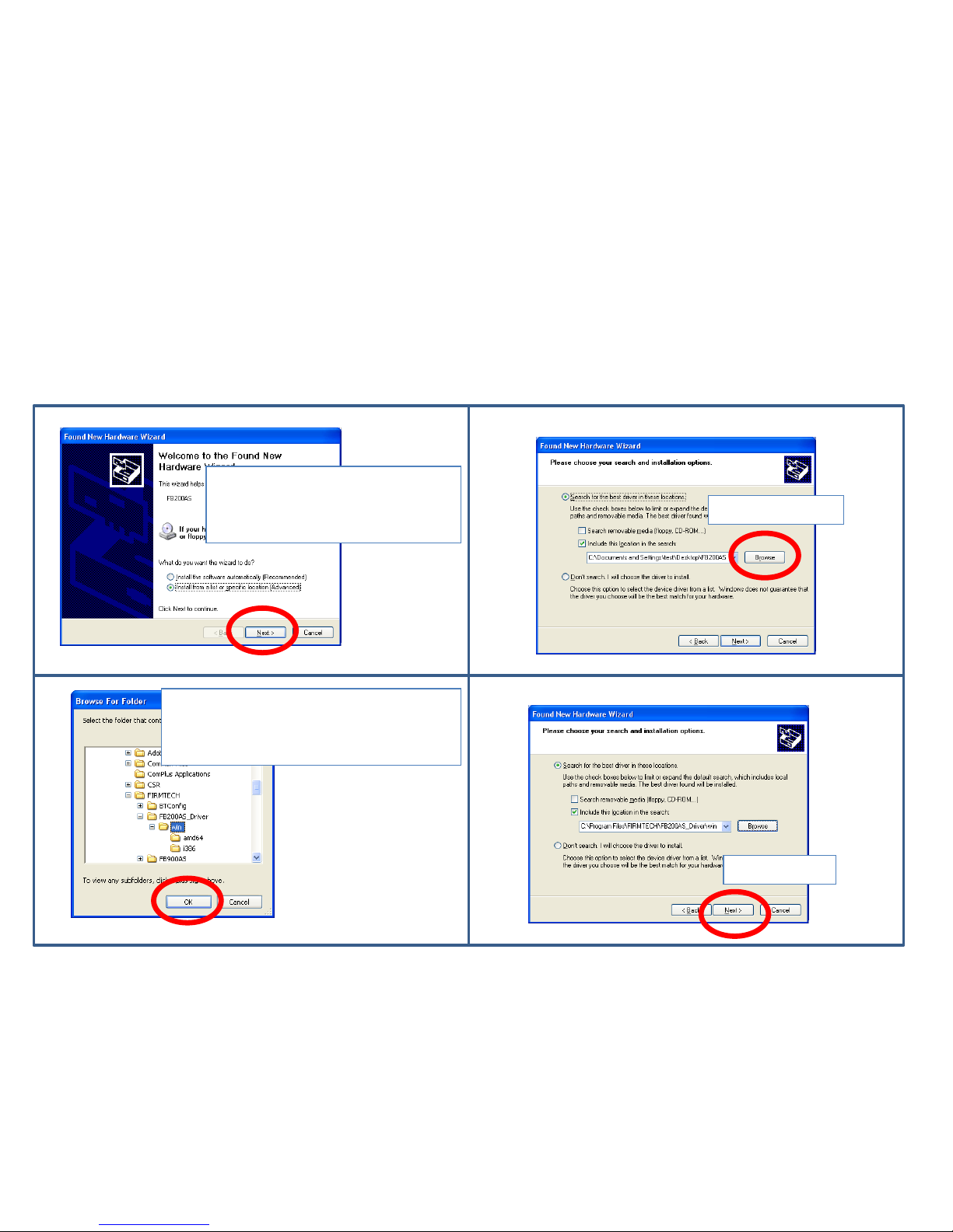
(2) Driver installation 1
Select a (Advanced) of list or
specific location installation.
Click "Next."
Click “Browse”.
Select “C:\Program Files \FIRMTECH
\FB200AS_Driver\win.”
Click “OK“.
Click “Next”
⑴ ⑵
⑶ ⑷
Page 26
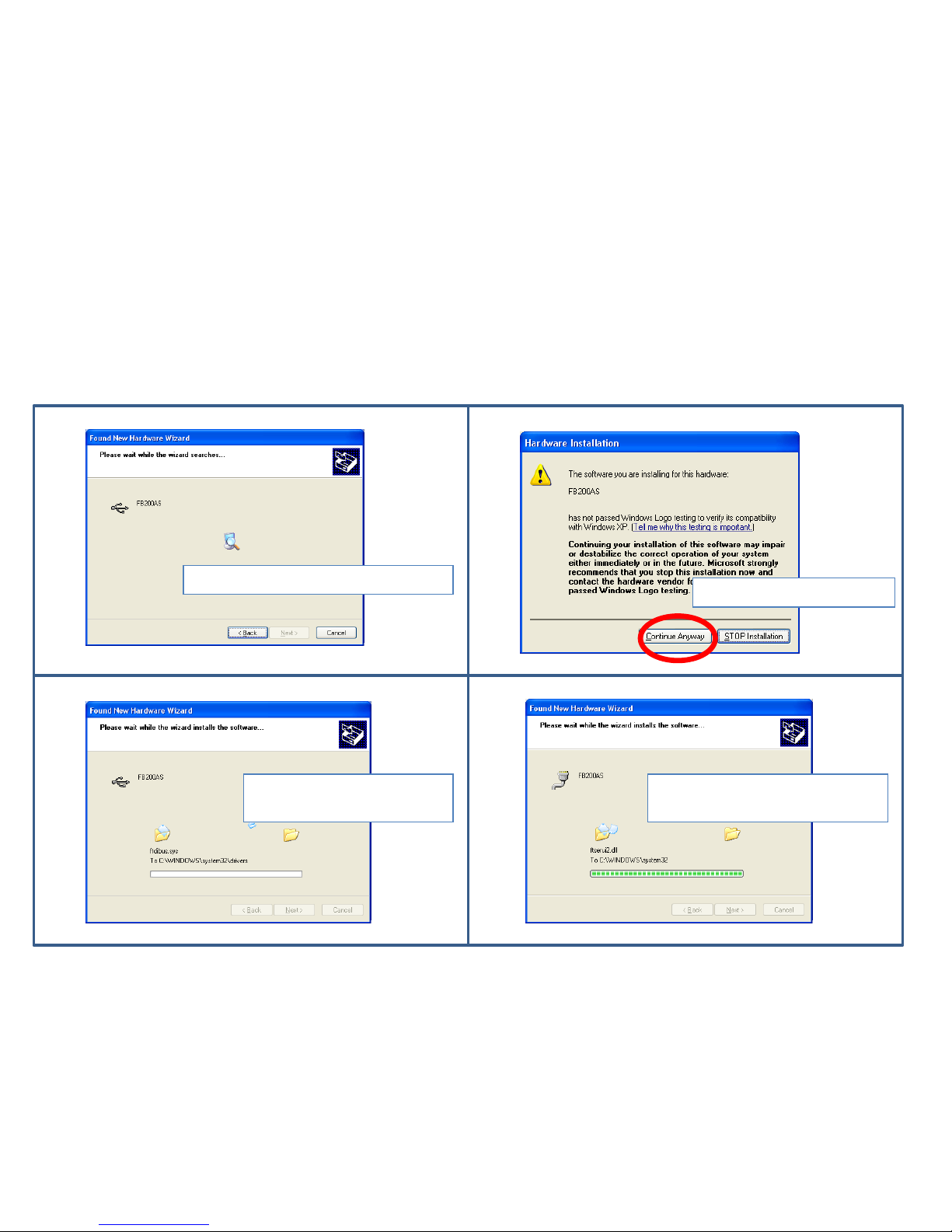
(3) Driver installation 2
Wait while a index is progressed.
Click “Continue Anyway”
Wait while a installation
is progressed.
Wait while a installationis is
progressed.
⑺ ⑻
⑸ ⑹
Page 27
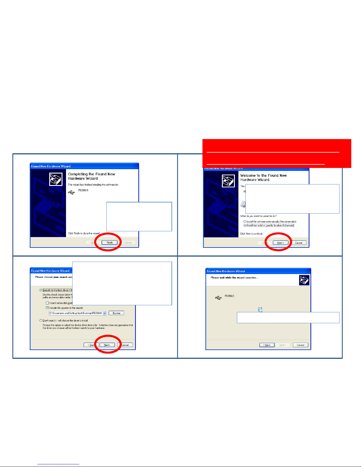
(4) Driver Installation 3
Click “finish.”
Driver installation is
not finished yet.
Select a (Advanced) of list or
specific location installation.
Click "Next."
Soon, Driver installation will
be processed once more.
Click"Next" because a setup
route is still remained at the
first installation.
Select a setup route at the first
installation if a route is wrong.
Wait while a index is progressed.
⑼ ⑽
⑾ ⑿
Page 28
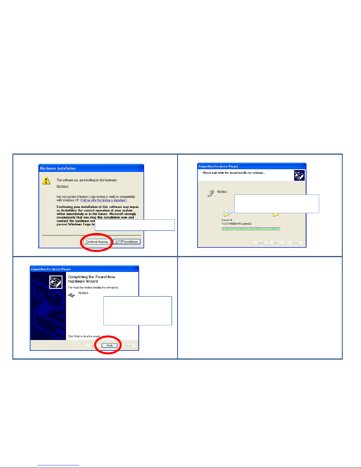
(5) Driver Installation 4
Power-supply of FZ200BS remains ON.
Click “Continue Anyway"
Wait while a installation is
progressed.
Click“finish.”
Driver installation is
finished.
⒀
⒂
⒁
Page 29
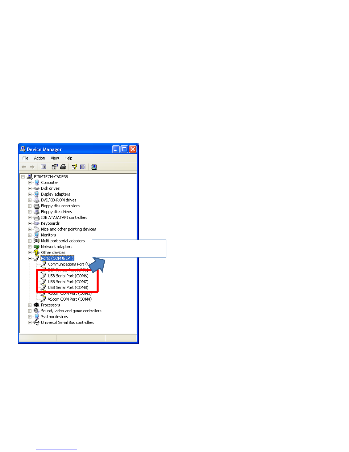
(6) Driver Installation Retrieval & Virtual Serial Port Number
• By using three FZ200BS at FZ200BS Quick Guide,
FZ200BS driver installation should be progressed
three times.
• Three setup finished FZ200BS is not progressed a
installation any more if FZ200BS Driver
installation is progressed three times in order to
use three devices of FZ200BS.
• The first assigned virtual serial port is used as it is
if three virtual serial port of FZ200BS is assigned
each and a registry of OS is not changed
• Progress FZ200BS Driver installation again in
order to use other FZ200BS besides previous
installed FZ200BS.
• Newly installed FZ200BS should be assigned a
virtual serial port of new number.
Virtual Serial Port setup
at three FZ200BS.
Page 30
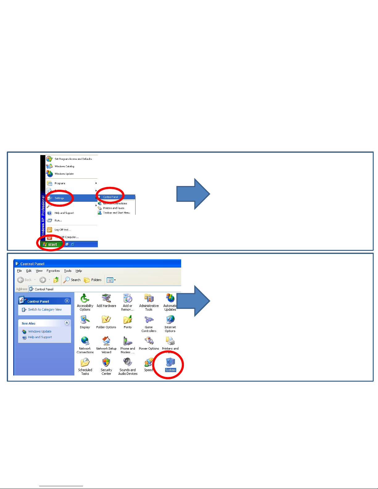
4. FB200AS Driver Confirmation Method
• Execute "SYSTEM" in control Panel.
(1) “Control Panel” & “System” Execution
• Click “Start” on Windows Start menu.
• Click “Settings.”
• Click “Control Panel.”
⑴
⑵
⑶
Page 31
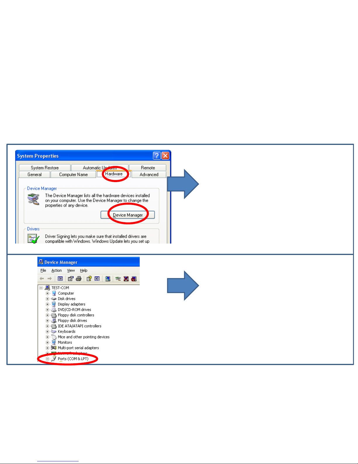
(2) “Device Manager” & “Port” Selection
• Select "Hardware" tab in system
Properties window.
• Select “Device Manager.”
• Select "Port" in Device Manager."
Page 32
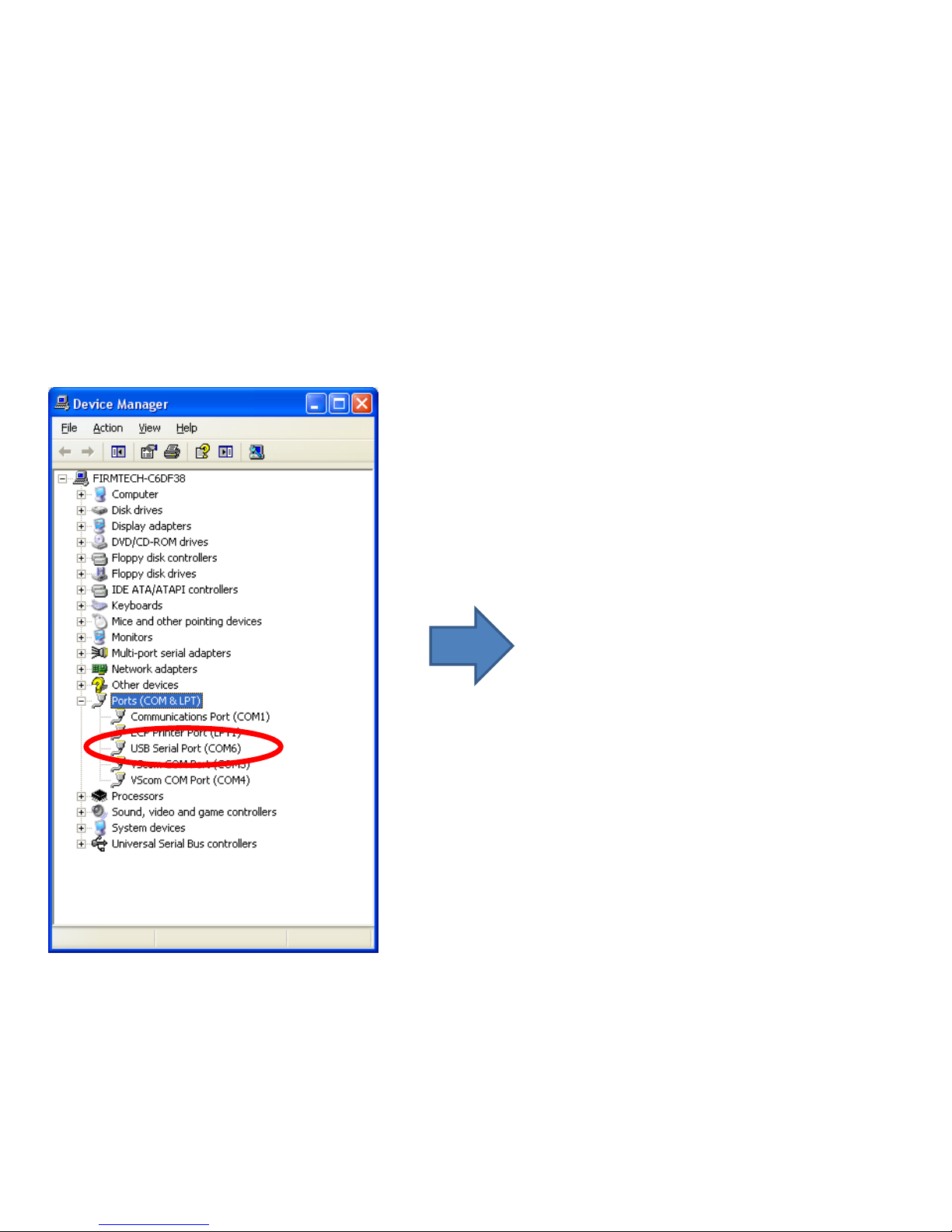
• Virtual serial port creation is confirmed
if FZ200BS Driver is installed normally
and FZ200BS power-supply is ON.
• "COM6" creation is confirmed in virtual
serial port.
• Virtual serial port number is created
differently according to user's
environment.
• OFF FZ200BS power-supply if a virtual
serial port number is confirmed.
(3) A created Virtual Serial Port Confirmation
Page 33

[2] Virtual Serial Port
Matters to be attended to
Page 34
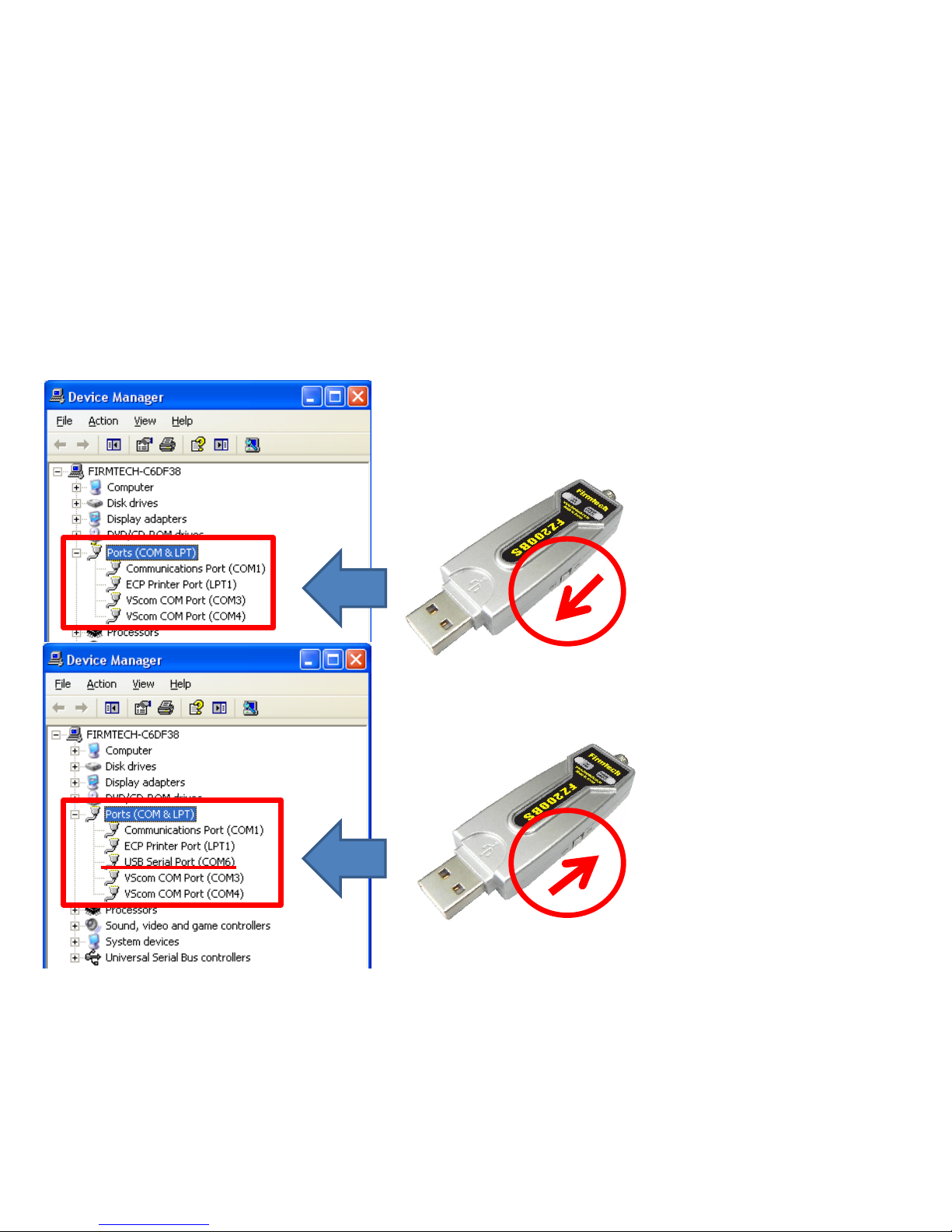
There is no "virtual serial
port in "port agenda" if a
power-supply of FZ200BS
is OFF.
1. A creation of Virtual Serial Port
(1) Virtual serial port & FZ200BS
There is "virtual serial port
in "port agenda" if a power-
supply of FZ200BS is ON.
Page 35
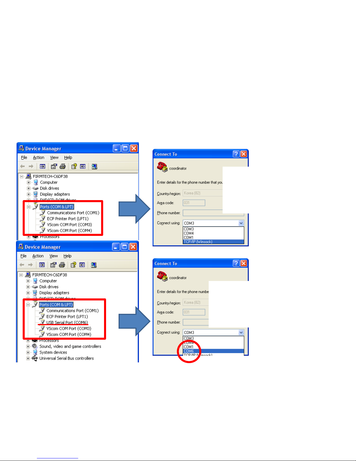
(2) Virtual Serial Port & Serial Communication Program
Virtual port connection is
impossible in serial program
like the hyper terminal if there
is no a virtual serial port.
Virtual port connection is possible
in serial program like the hyper
terminal if there is a virtual serial
port.
Page 36
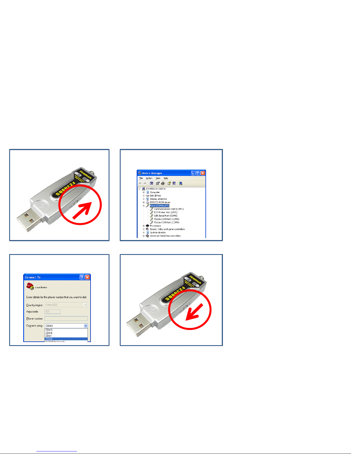
(3) Virtual Serial Port & Serial Communication Program & FZ200BS
⑴ Power Supply ON
⑵ Virtual Port Creation
⑶ Virtual Port OPEN
⑷ Power Supply OFF
• Virtual port may be disappeared by
power-supply OFF of FZ200BS while
using virtual serial port created at
serial communication program.
• Even though a virtual serial port is
disappeared by power supply OFF of
FZ200BS,may not see virtual serial
port disappearing at serial
communication program.
• Communication is not available
because of realistic port(Virtual Port)
disappearing even though serial
communication program is operated
normally.
• There may occur critical situation at
OS if virtual port is disappeared
under a serial communication
program operating.
• Therefore, certainly, serial
communication program should be
finished before power-supply OFF of
FZ200BS. That is, the power supply
of FZ200BS should be OFF under
finishing virtual port.
Page 37
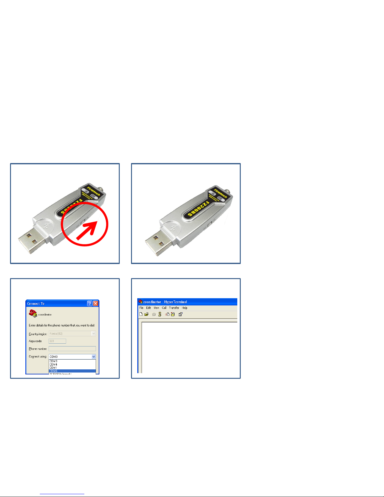
(4) Virtual Serial Port & FZ200BS & Start Message
⑴ Power-Supply ON ⑵ Message Output
⑶ Virtual Port OPEN ⑷ No Message
• Start Message is made out if powersupply of FZ200BS is ON.
• Virtual Port is created after powersupply of FZ200BS is ON.
• Serial communication program is
available after virtual port creation.
• Can not see operation-situation (Start
Message etc) immediately just after
ON of module power supply if serial
communication program is used a
virtual port.
• In case of using a virtual port, a user
can not see Start Message output of
FZ200BS immediately.
Page 38

[3] FZ200BS Operating
&
Reset
Configuration setting with AT Command
Page 39
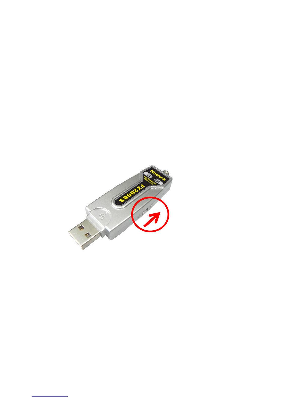
1. Operating FZ200BS
(1) FZ200BS Power ON
• Turn the power switch on.
Page 40
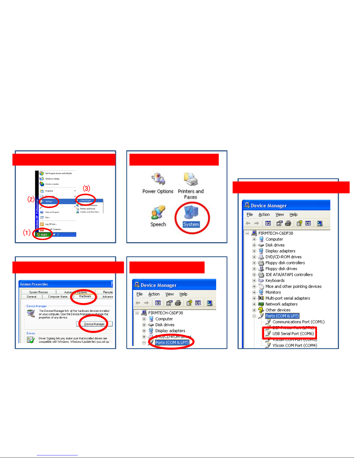
Virtual Serial Port Number Confirmation
1. “Control Panel” Execution 2. “System” Execution
3. “Device Manager" Execution 4. “Port” Selection
5. “Port Number” Confirmation
Page 41
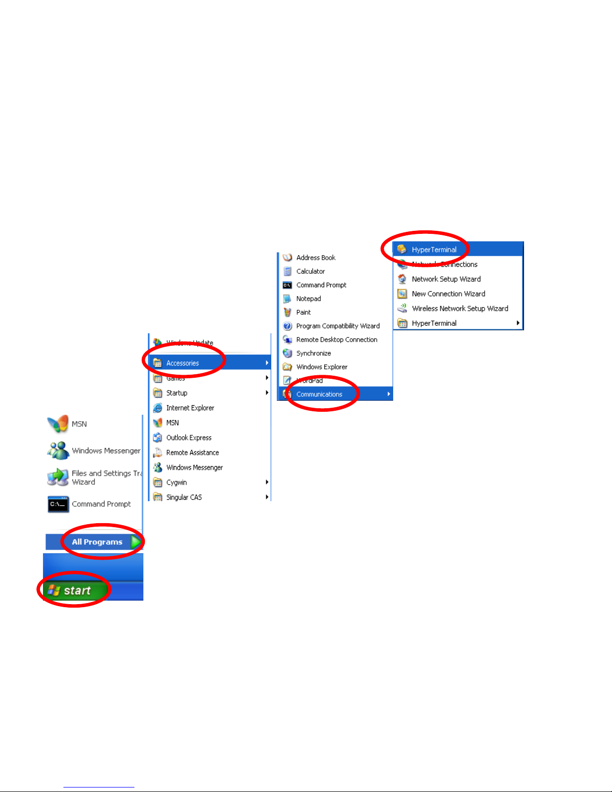
(2) Hyper Terminal Execution
• Click “Start” on Windows Start menu.
• Click “All Programs.”
• Click “Accessories.”
• Click “Communications.”
• Click “Hyper Terminal.”
⑴
⑵
⑶
⑷
⑸
Page 42
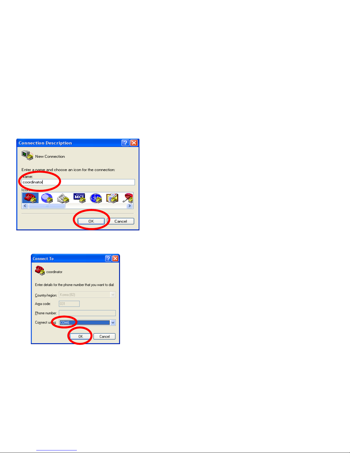
• Set up Hyper terminal connected with FZ200BS
that is set to Coordinator
• Input “coordinator” in the “Name” space.
• Select “OK” and go forward.
(3) Hyper terminal set-up – Name
(4) Hyper terminal set-up – Use Port
⑴
⑵
⑶
⑷
• Select the port connected with FZ200BS that is set
to the Coordinator.
• Select “OK” and go forward.
Page 43
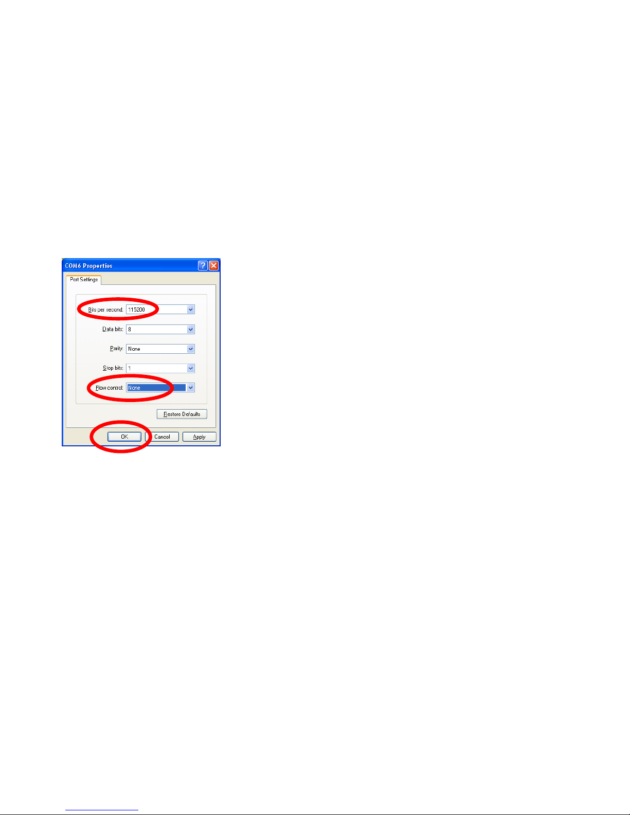
• Set “115200” in the “Bit/Sec(B)” space
• Set “None” in the “Flow control(F)” space
• Do not change other requirements.
• Select “OK”
(5) Hyper terminal Set-up – Signal Speed and etc
⑸
⑹
⑺
Page 44
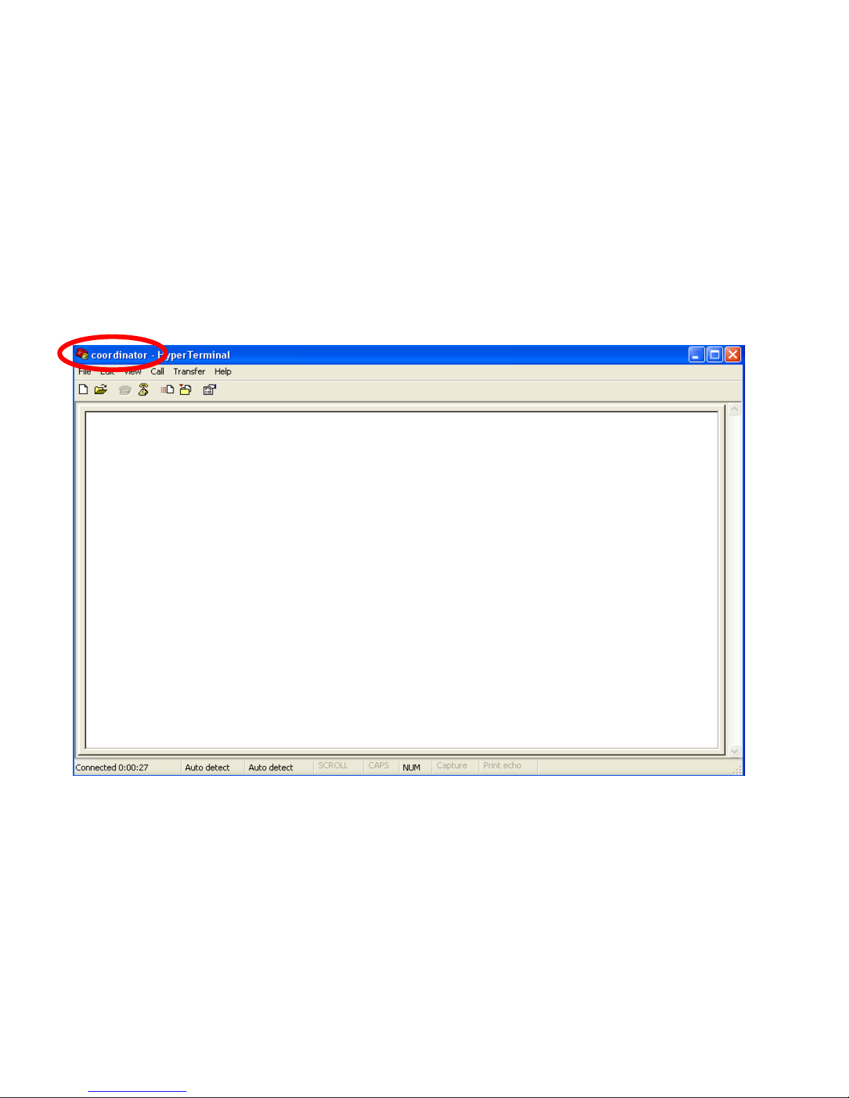
• Hyper terminal connected with FZ200BS that is set
to Coordinator is completed
• To set up the Hyper terminal to Router, follow the
same steps, but connect to “Port7”. “Router”
should be put in the Name space.
• To set up the Hyper terminal to Router, follow the
same steps, but connect to “Port8”. “End” should
be put in the Name space.
(6) Hyper terminal set-up - completion
Page 45
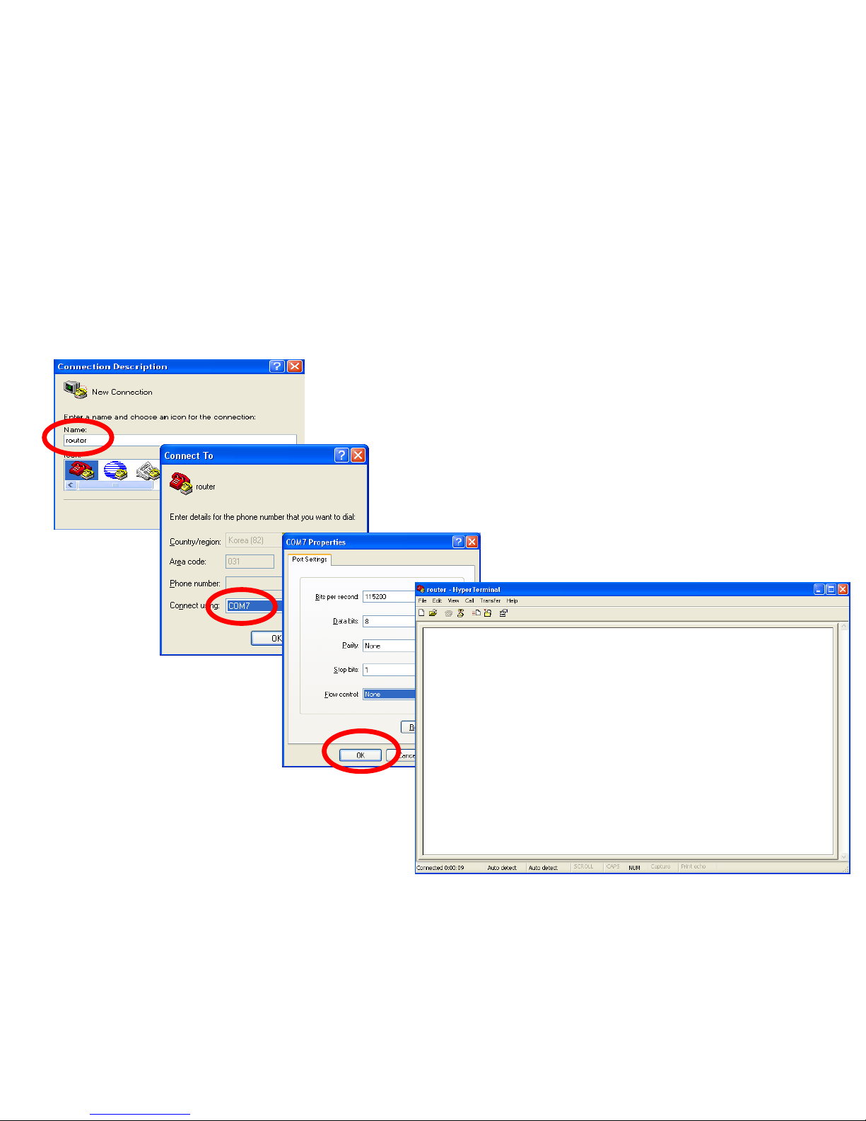
If you want to use FZ200BS as Router, step by step diagram below – Use Port 7
Page 46
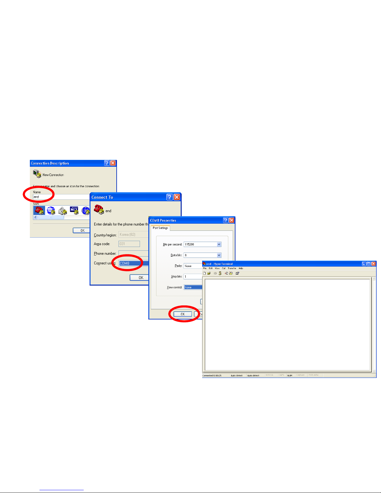
If you want to use FZ200BS as End Device, step by step diagram below – Use Port 8
Page 47
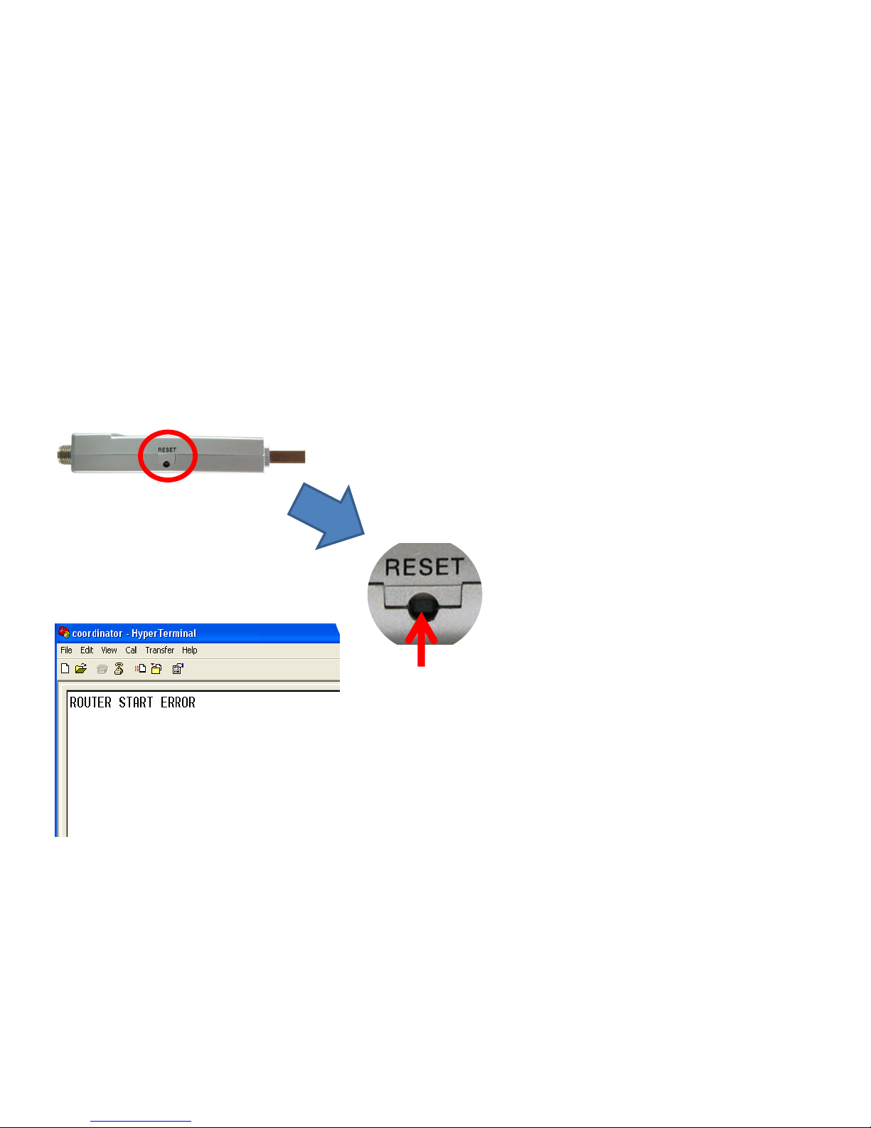
FZ200BS Reset
• FZ200BS uses virtual serial port. Therefore,
FZ200BS will be operated before serial
communication program like hyper terminal.
• Here is all start message output made before hyper
terminal execution. So execute reset of FZ200BS, in
order to make an output of start message again.
• Confirm "RESET" of a side “FZ200BS".
• Press a Reset Switch in hole by using tweezers.
• FZ200BS is operated if start message output is made
from hyper terminal.
Page 48
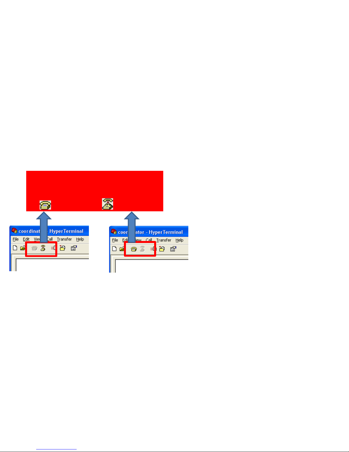
FZ200BS connection condition check-sequence
• Finish hyper terminal or the condition
connected with virtual serial port, if
FZ200BS is not operated normally or
any word output is not made from
hyper terminal. (Please refer to the left
in order to disconnect virtual serial
port.)
• Restart FZ200BS by pressing OFF and
then ON switch of FZ200BS power-
supply.
• Confirm communication speed and
other connection agendas.
< Condition using virtual
serial port >
Disconnected with virtual port on hyper
terminal using virtual port by changing
to( ) after clicking ( ).
< Condition not using virtual
serial port >
Page 49
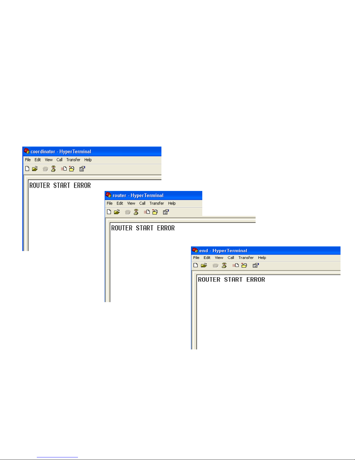
(7) Hyper Terminal Output
• Turn the power of 3 FZ200BS on &
reset.
• Since they are all set to Factory
setup, the 3 FZ200BS are
supposed to output “ROUTER
START” and “ERROR”.
Page 50
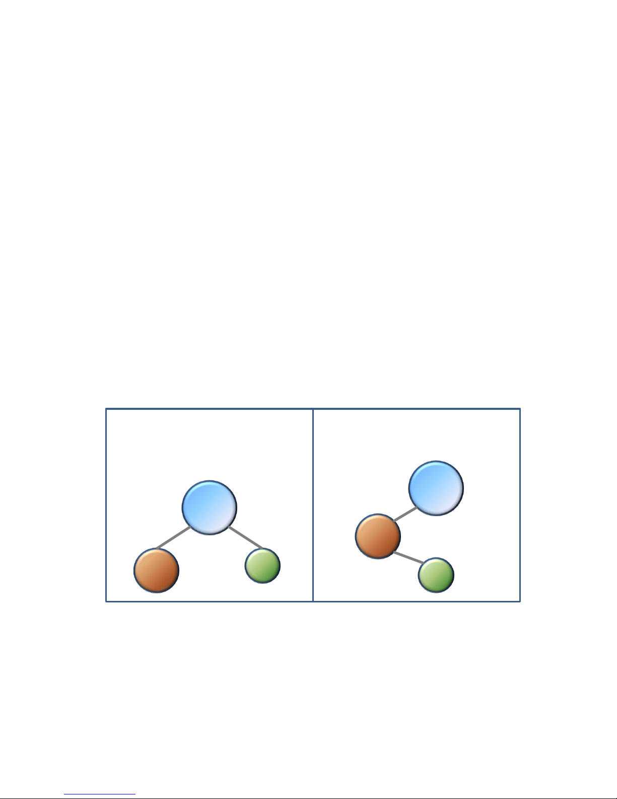
[4] FZ200BS Set-up
&
ZigBee Network Construction
Coordinator
Router
End
Example 1. Zigbee network
construction
Coordinator
Router
End
Example 2. Zigbee network
construction
Page 51
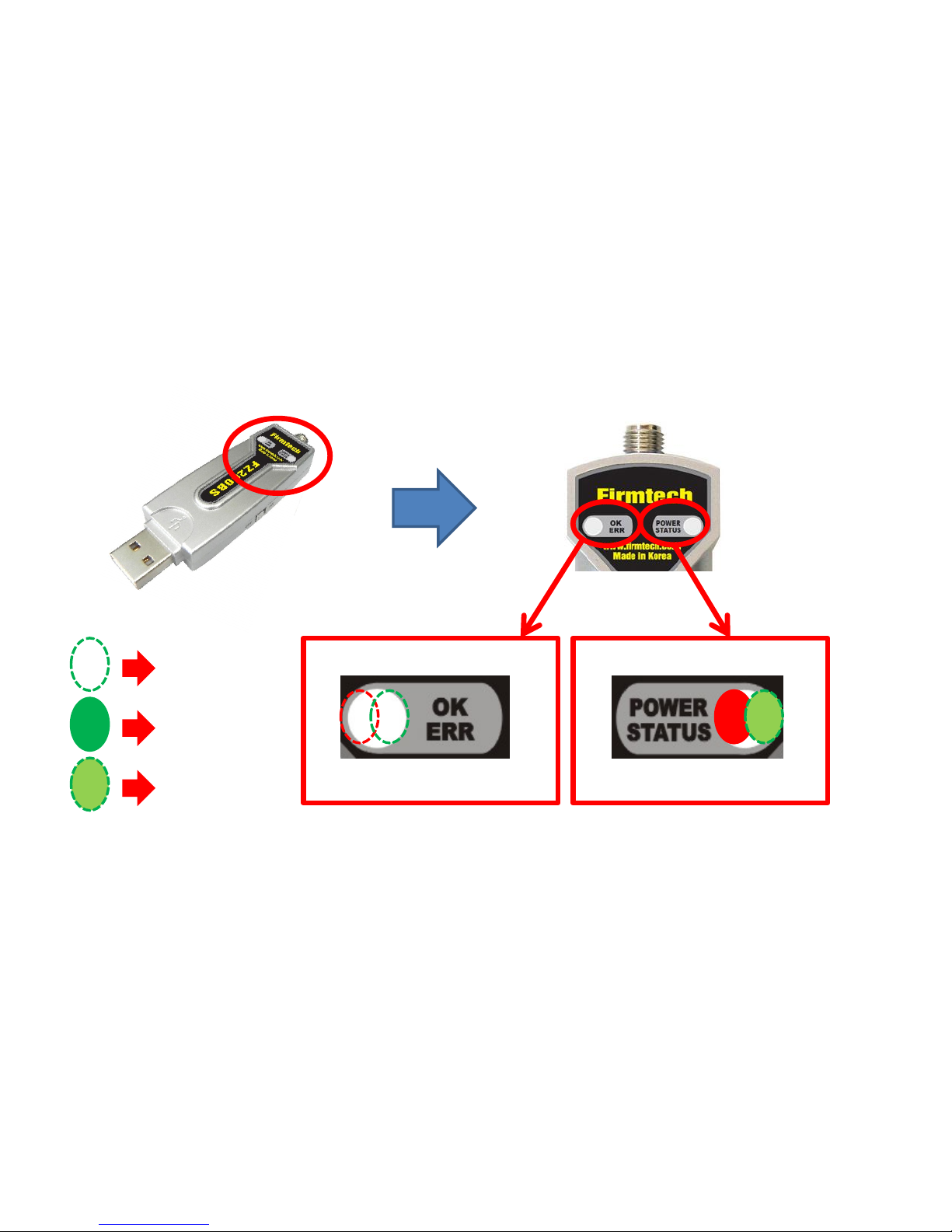
The Status LED condition of Operation Mode when Network construction/participation is
failed
OFF LED
ON LED
Blink LED
• The POWER LED displays a red light if FZ200BS power supply is ON.
• The Green STATUS LED blinks quickly every 0.1 sec because Network construction
/ Participation has yet to be successful.
• The OK/ERR LED keep being turned off when FZ200BS is in an Operation Mode.
Page 52
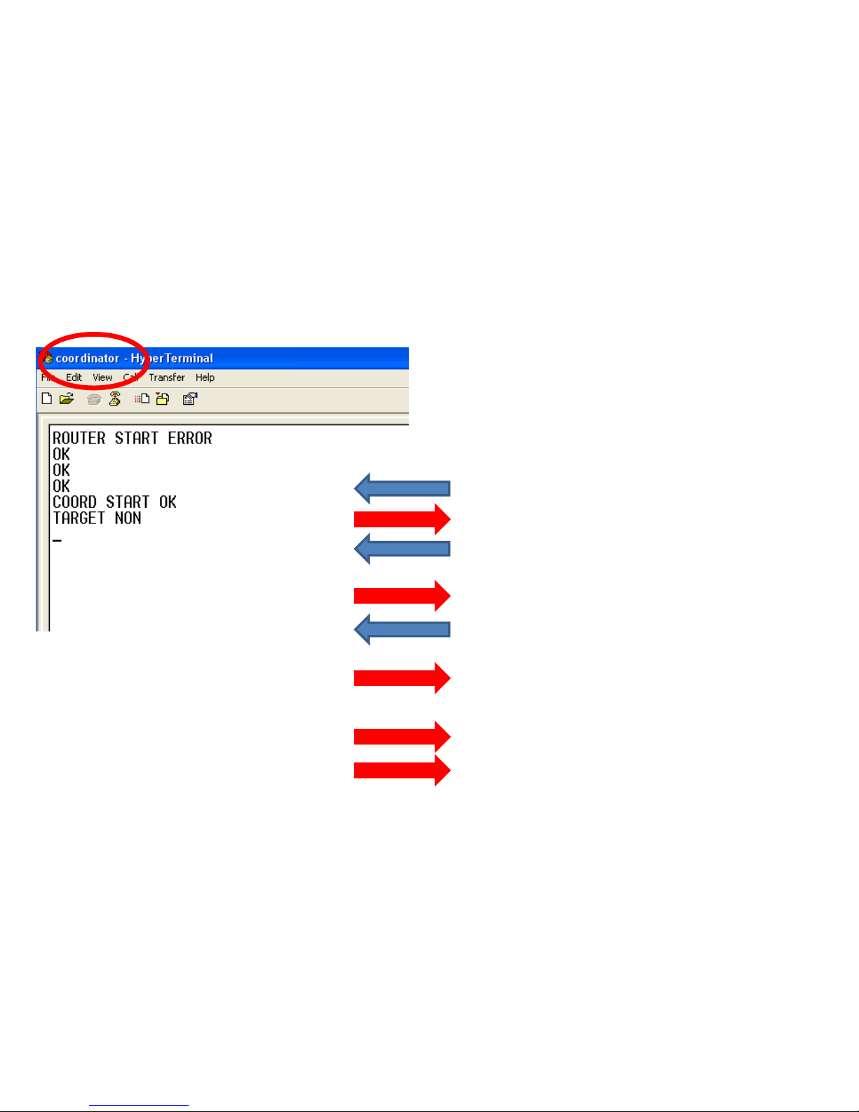
• Input the following into Hyper terminal
connected to FZ200BS that is set to
Coordinator
• Input“+++”in Hyper terminal.
• “OK” is output from FZ200BS.
• After inputting “AT+SETCOORD” in Hyper
terminal, press Enter key.
• “OK” is output from FZ200BS.
• Press Enter key after inputting “ATZ” in
Hyper terminal.
• “OK” is output from FZ200BS
• FZ200BS Device is re-started
• “COORD START OK” is output
• “TARGET NON” is output
1. FZ200BS Coordinator Set-up & ZigBee Network Construction
Page 53
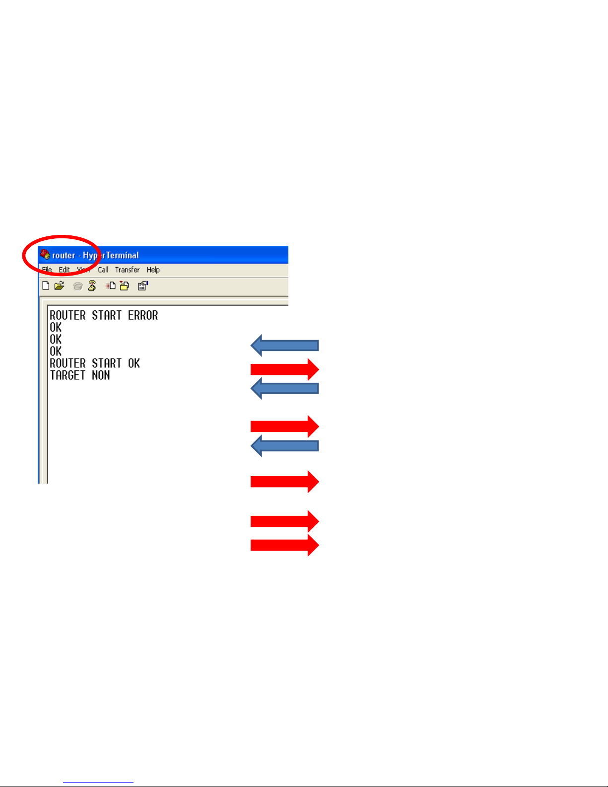
2. FZ200BS Router set-up & ZigBee Network Participation
• Input the following into Hyper Terminal
connected to FZ200BS that is set to Router
• Input“+++”in Hyper terminal.
• “OK” is output from FZ200BS.
• After inputting “AT+SETROUTER” in Hyper
terminal, press Enter key.
• “OK” is output from FZ200BS.
• After inputting “ATZ” in Hyper Terminal,
press Enter key.
• “OK” is output from FZ200BS
• FZ200BS Device re-started.
• “ROUTER START OK” is output.
• “TARGET NON” is output.
Page 54
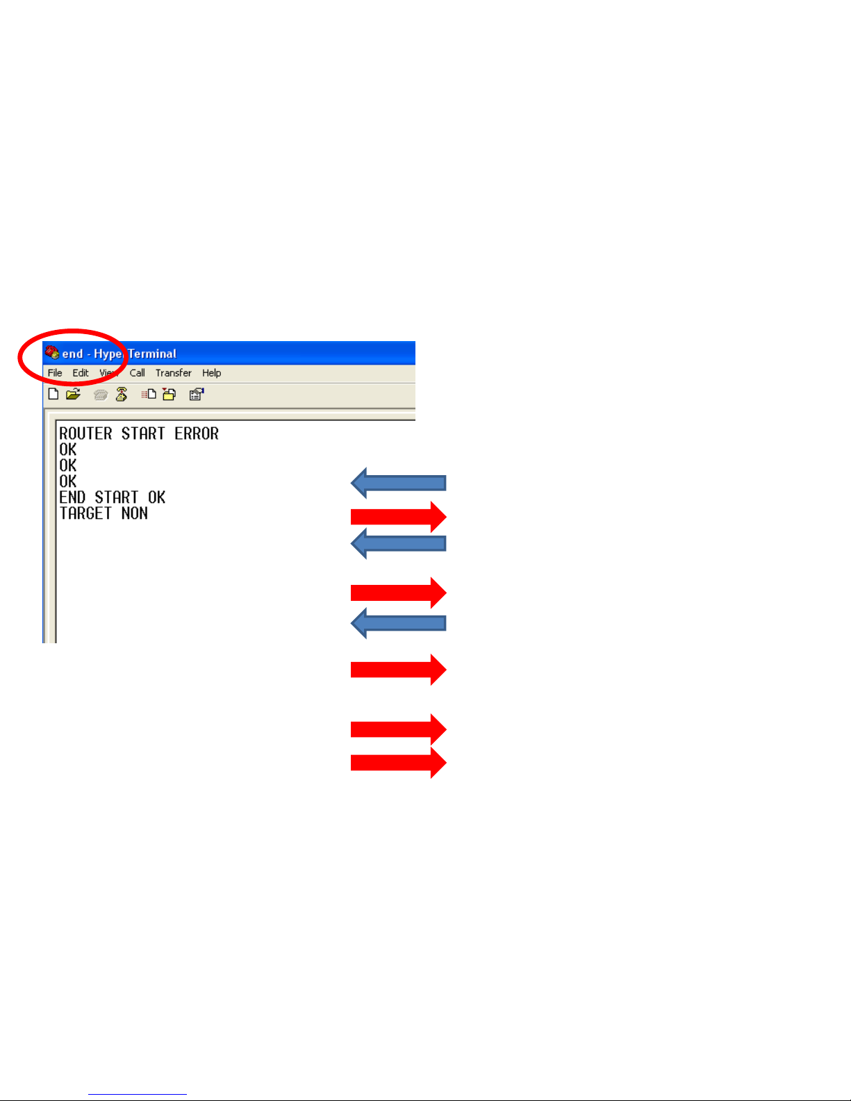
3. FZ200BS End Device set-up & ZigBee Network Participation
• Input the following into Hyper terminal
connected to FZ200BS that is set to End
Device
• Input“+++”in Hyper terminal.
• “OK” is output from FZ200BS.
• After inputting “AT+SETEND” in Hyper
terminal, press Enter key.
• “OK” is output from FZ200BS.
• Press Enter key after inputting “ATZ” in
Hyper terminal.
• “OK” is output from FZ200BS.
• FZ200BS Device re-started.
• “END START OK” is output.
• “TARGET NON” is output.
Page 55
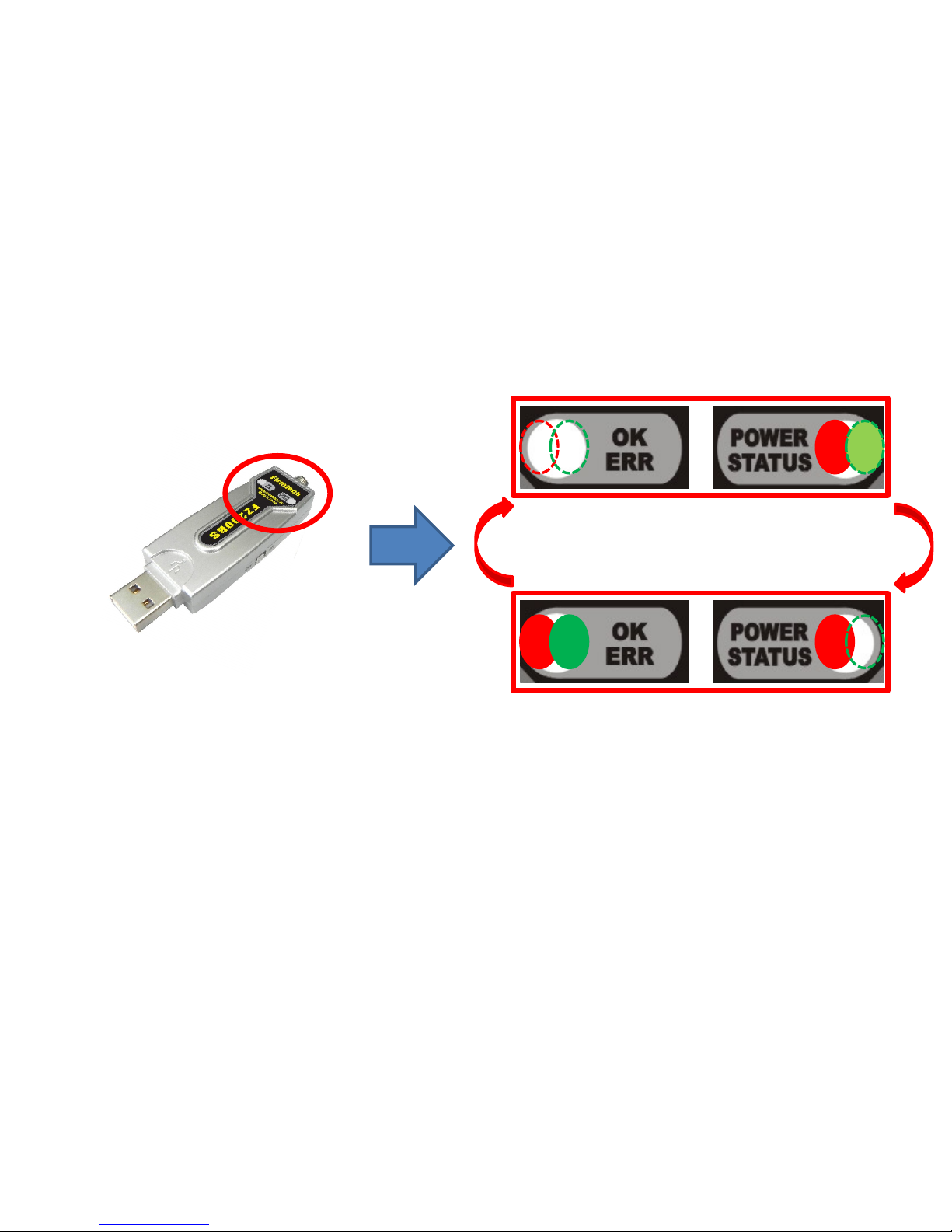
STATUS/OK/ERR LED conditions in AT Command Mode
Switched AT Command
Mode
Switched
Operation Mode
• Mode is switched from Operation to AT Command when you input “+++” in Hyper Terminal.
• The Green STATUS LED keeps being turned off when FZ200BS is in an AT Command Mode.
• The OK/ERR LED holds the light turned on when FZ200BS is an AT Command Mode.
• Mode is switched from AT Command to Operation by inputted “ATO” into Hyper Terminal and pressing
enter key.
• In the AT Command mode, you can change the mode to operation mode by inputting “ATZ” into Hyper
Terminal and pressing enter key. In this case device is reset simultaneously.
Page 56
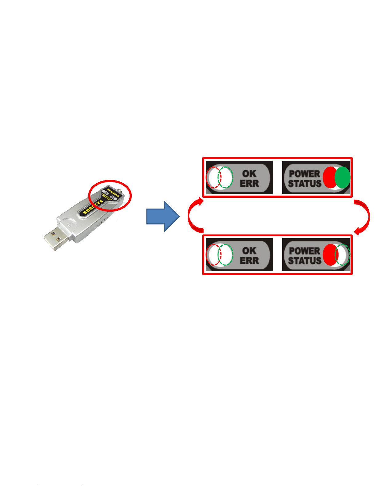
STATUS LED conditions of Operation Mode when Network Construction/Participation
is completed.
Every 1 sec
Green STATUS LED OFF
Every 0.1 sec
Green STATUS LED ON
• When Network Construction/Participation is completed, the Green STATUS LED blinks
every 1 second.
• The OK/ERR LED of FZ200BS keeps being turned off.
• When Network Construction/Participation is completed for the first time, it is
automatically proceeded from the next even if device is reset.
Page 57
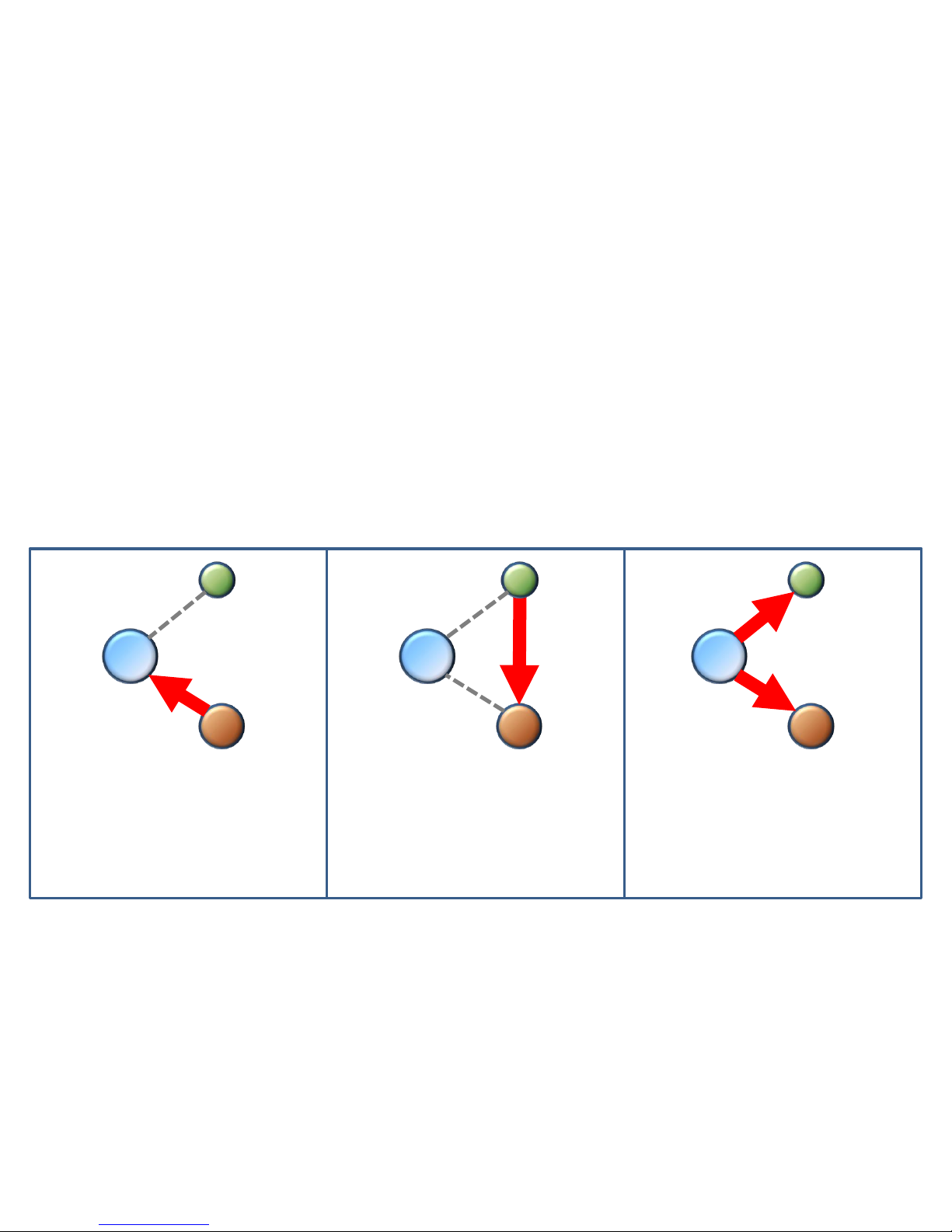
[5] FZ200BS
Setting up Target Device
Coordinator
Router
End
Coordinator
Router
End
Coordinator
Router
End
In order to communicate,
Router should be aware
of Coordinator’s address.
In order to
communicate, End
Device should be
aware of Router’s
address.
In order to communicate,
Coordinator uses
Broadcast’s address.
Page 58
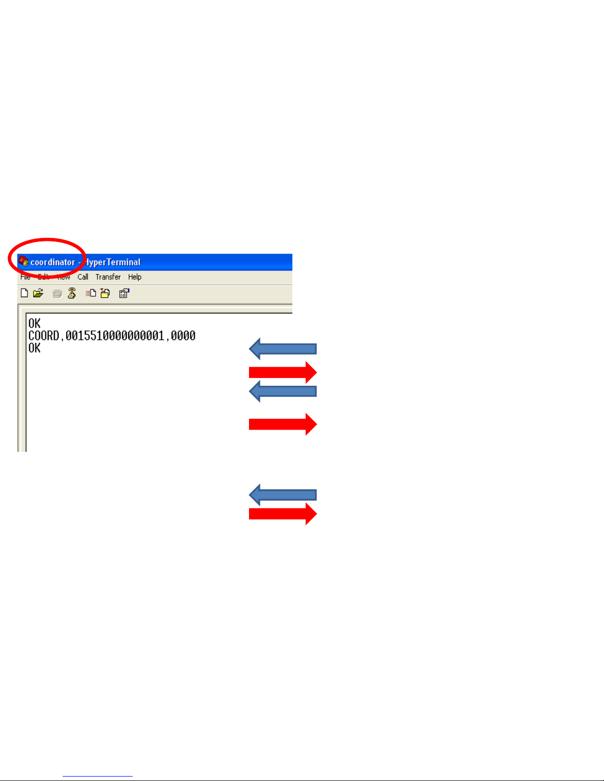
• Input the following into Hyper terminal
connected to FZ200BS that is set to
Coordinator
• Input “+++”
• “OK” is output from FZ200BS
• After inputting “AT+GETLOCAL” and press
Enter key.
• “COORD, 0015510000000001, 0000” is
output from FZ200BS
• IEEE ADDRESS of Coordinator is
“0015510000000001”
• After inputting “ATO”, Enter key.
• “OK” is output
1. Setting Target Device of Router to Coordinator(Router ->Coordinator)
(1) Coordinator IEEE address search
Page 59
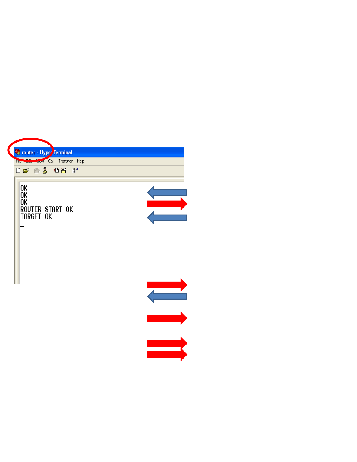
(2) Setting Target Device of Router to Coordinator
• Input the following into Hyper Terminal
connected to FZ200BS that is set to Router
• Input “+++”
• “OK” is output from FZ200BS
• After inputting “AT+SETTARGET
0015510000000001”and press Enter key.
• 0015510000000001 is the address that has
already been searched before. If you use
another device, you should search the
address again because each device has its
own address.
• “OK” is output from FZ200BS
• After inputting “ATZ” in Hyper Terminal,
address Enter key.
• “OK” is output from FZ200BS
• Device is re-started.
• “ROUTER START OK” is output.
• “TARGET OK” is output.
Page 60
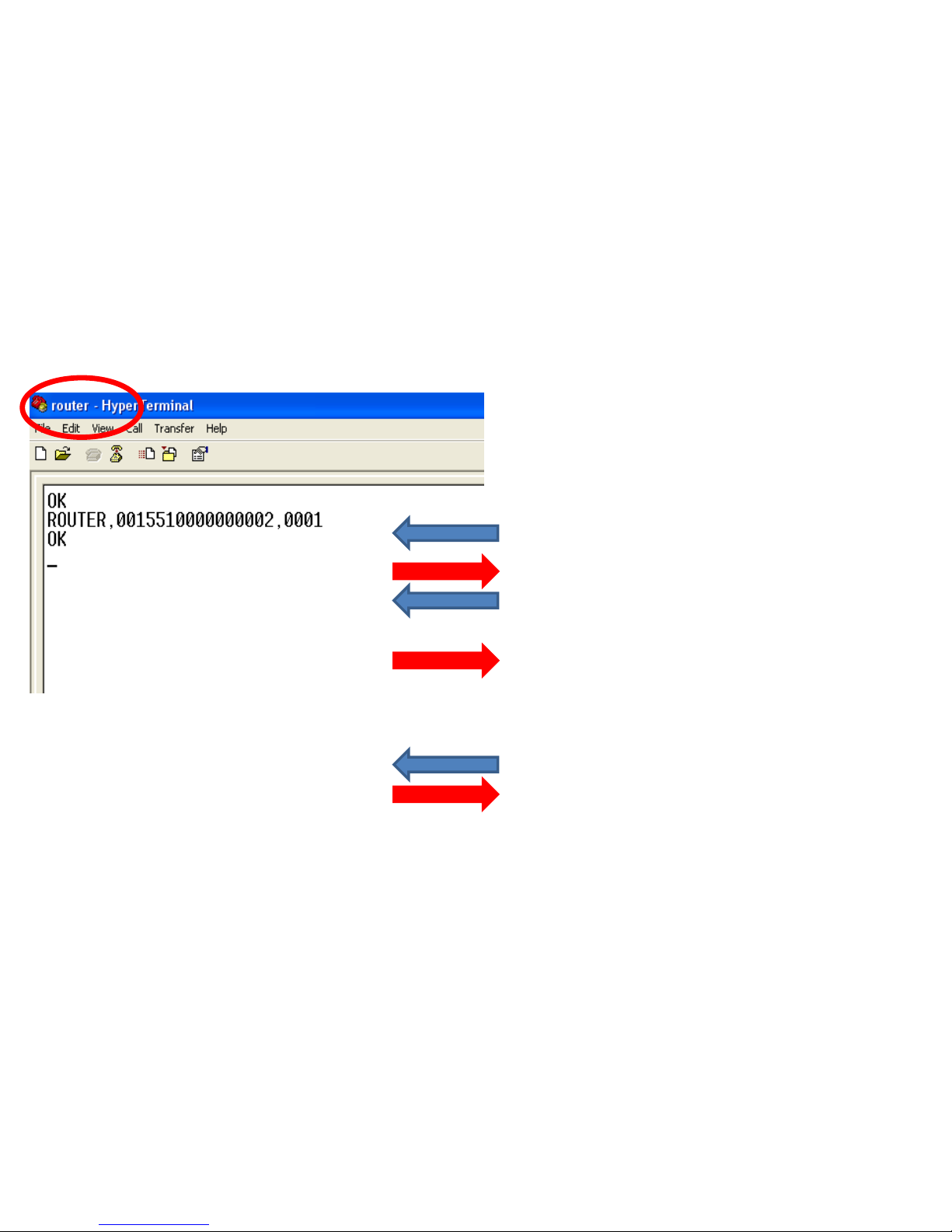
2. Setting Target Device of End Device to Router (End Device -> Router)
(1) Router device IEEE address search
• Input the following into Hyper Terminal
connected to FZ200BS that is set to Router
• Input “+++”
• “OK” is output from FZ200BS
• After inputting “AT+GETLOCAL” and press
Enter key.
• “ROUTER, 0015510000000002, 0001” is
output from FZ200BS
• IEEE address of Router is
“0015510000000002”
• After inputting “ATO”, press Enter key.
• “OK” is output.
Page 61
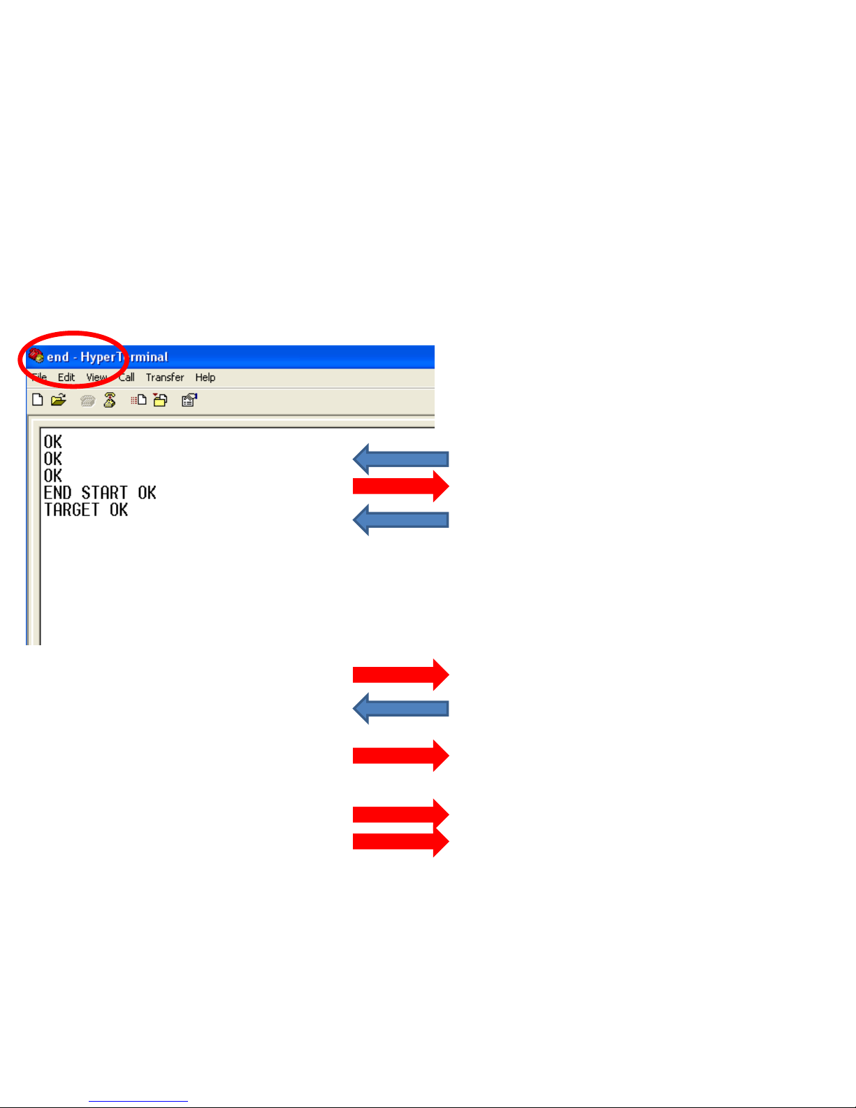
(2) Setting Target Device of End Device to Router
• Input the following into Hyper terminal
connected to FZ200BS that is set to End
Device
• Input “+++”
• “OK” is output from FZ200BS
• After inputting “AT+SETTARGET
0015510000000002” and press Enter key.
• 0015510000000002 is the address that has
already been searched before. If you use
another device, you should search the
address again because each device has its
own address.
• “OK” is output from FZ200BS
• After inputting “ATZ” in Hyper Terminal,
press Enter key.
• “OK” is output from FZ200BS
• Device is re-started
• “END START OK” is output
• “TARGET OK” is output
Page 62
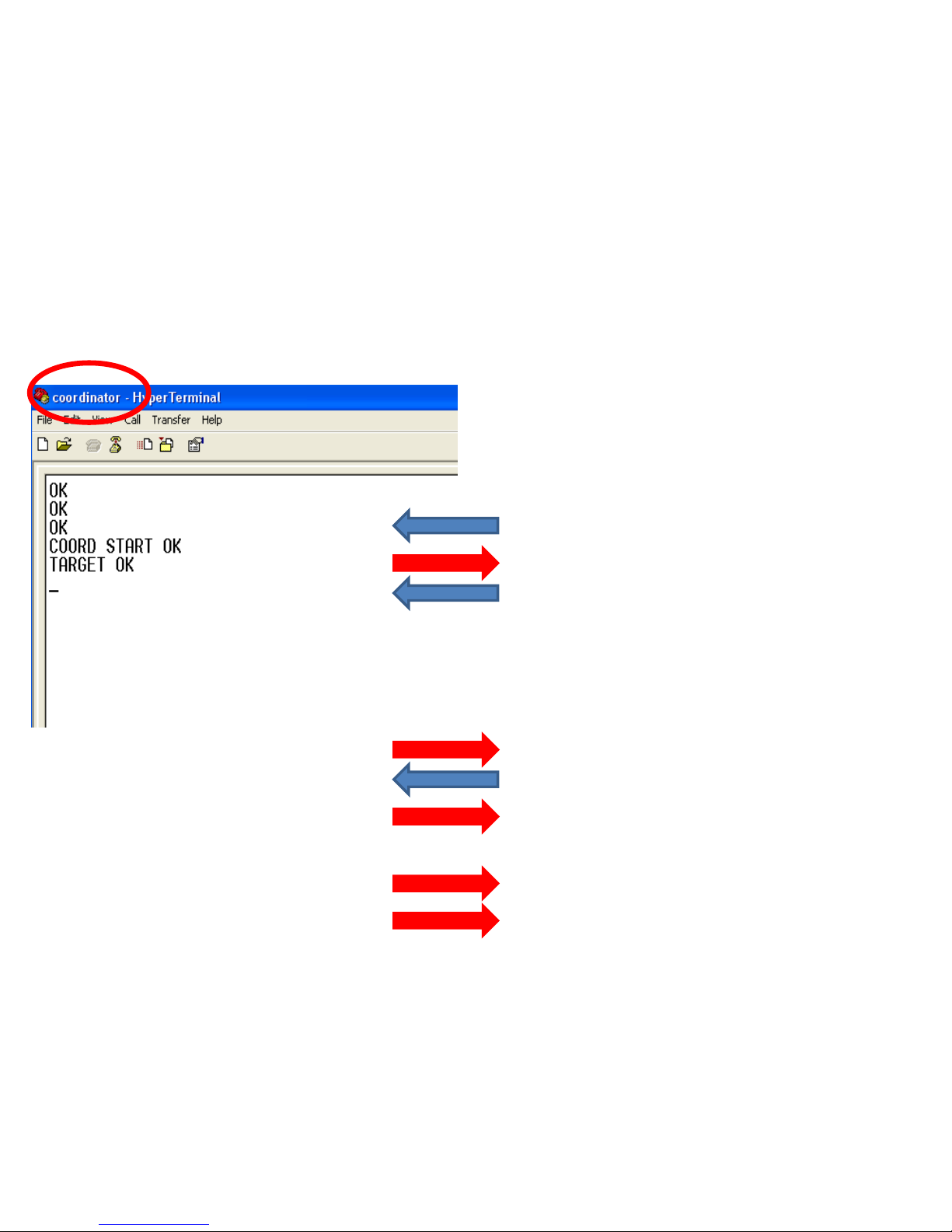
3. Setting the Target device of Coordinator to ALL Device
(Coordinator -> ALL Device)
• Input the following into Hyper terminal
connected to FZ200BS that is set to
Coordinator
• Input “+++”
• “OK” is output from FZ200BS
• After inputting
“AT+SETTARGETFFFFFFFFFFFFFFFF” and
press Enter key.
• FFFFFFFFFFFFFFFF is all devices that are
not in a low power consumption mode, and
still working with ZigBee Network
• “OK” is output from FZ200BS
• After inputting “ATZ” , press Enter key.
• “OK” is output from FZ200BS
• Device is re-started.
• “COORD START OK” is output.
• “TARGET OK” is output.
Page 63
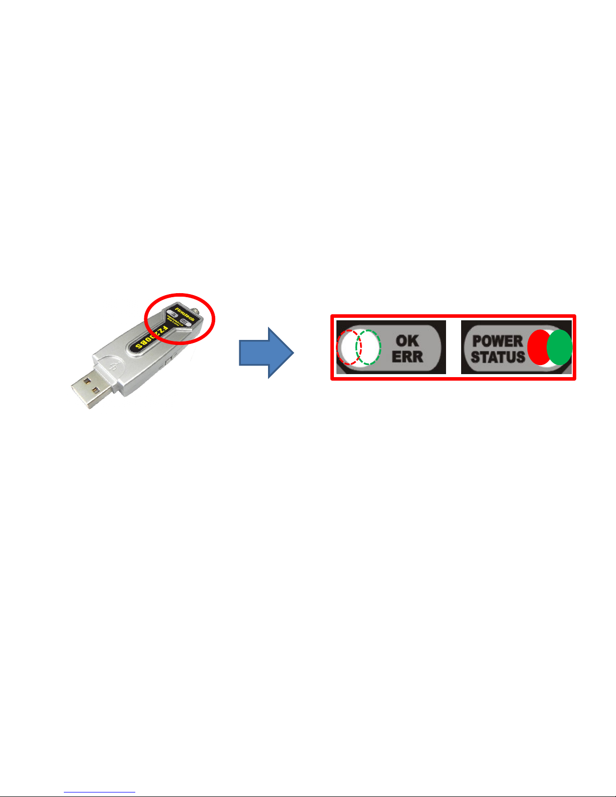
STATUS LED conditions of Operation Mode that was set to Target Device (Coordinator & Router)
• The Green STATUS LED keeps being turned ON after Target Device is set.
• The OK/ERR LED keeps being turned OFF in an Operation Mode.
• Once Target Device set-up is done for the first time, it is automatically proceeded
from the next even if the device is reset.
Page 64
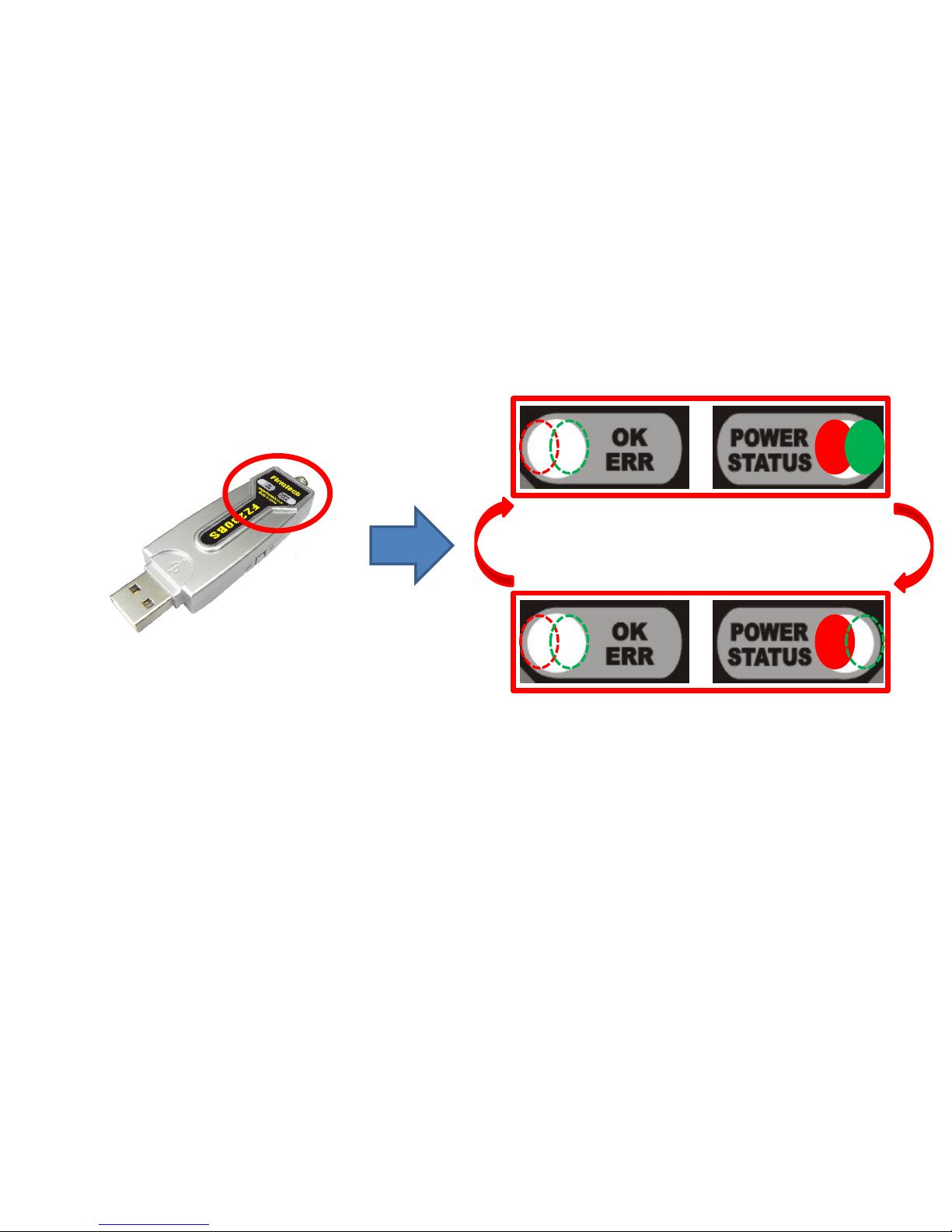
Low power
consumption Mode
in 1 second
Wake Up in
10 seconds
STATUS LED conditions of Operation Mode that was set to Target Device (End Device)
• The Green STATUS LED keeps being turned ON after Target Device is set.
• The OK/ERR LED keeps being turned OFF in an Operation Mode.
• After Target Device is set, End Device automatically goes into low power consumption
mode and makes wake-up every certain time that is currently set to 10 seconds.
• Once Target Device set-up is done for the first time, it is automatically proceeded
from the next even if the device is reset.
Page 65
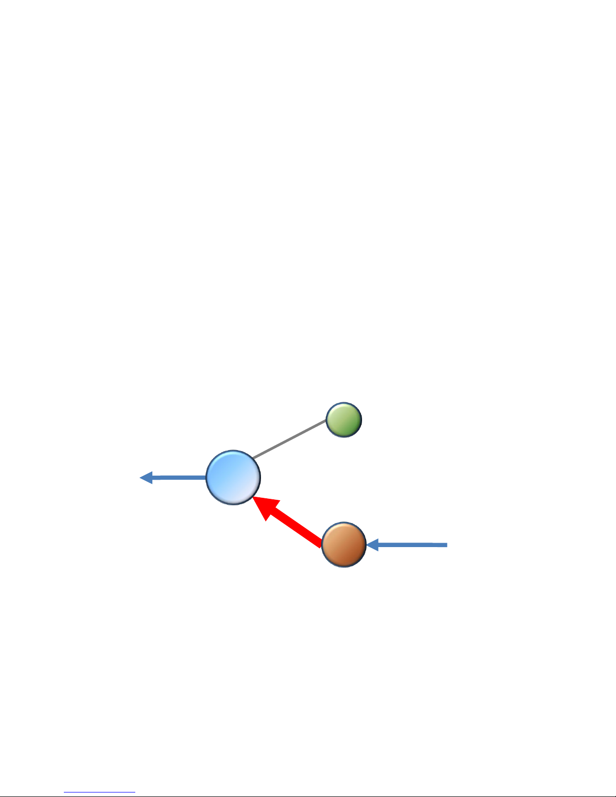
SERIAL
SERIAL
Coordinator
Router
End
[6] Serial Data transmission
from Router to Coordinator
Page 66
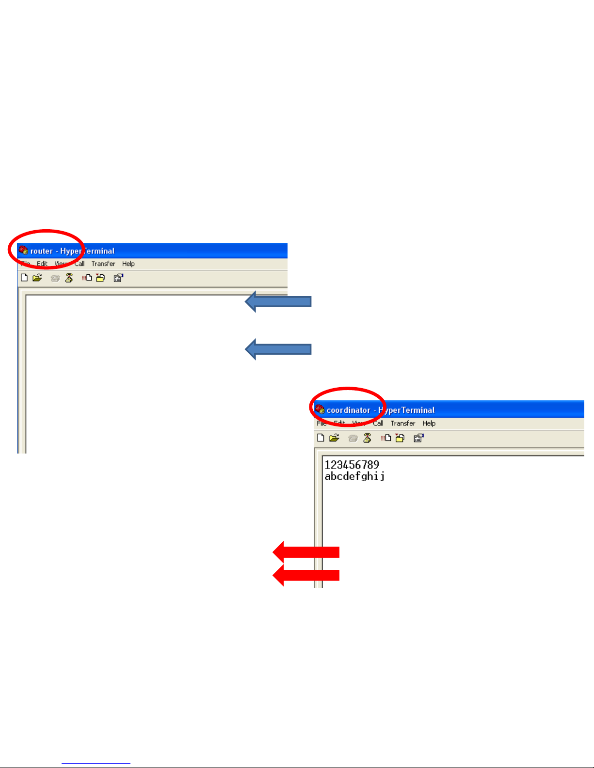
(1) Serial Data Input in Router – Check it in Coordinator.
• Input the following into Hyper Terminal
connected to FZ200BS that is set to Router
• After inputting “123456789” into Hyper
Terminal, press Enter key.
• After inputting “abcdefghij” into Hyper
Terminal, press Enter key.
• Displays the followings on Hyper Terminal
connected to FZ200BS that is set to
Coordinator
• “123456789” is output
• “abcdefghij” is output.
1. Serial Data Transmission “Router -> Coordinator”
Page 67
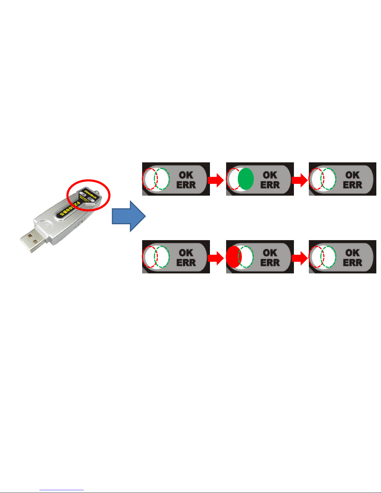
OK/ERR LED conditions related ACK after Data transmission. (Router)
< Case 1. ACK transmission is successfully done >
< Case 2. ACK transmission is failed >
• The Green OK LED blinks once if the Data transmission is successfully done.
• The Red ERR LED blinks once if the Data transmission is failed.
Page 68
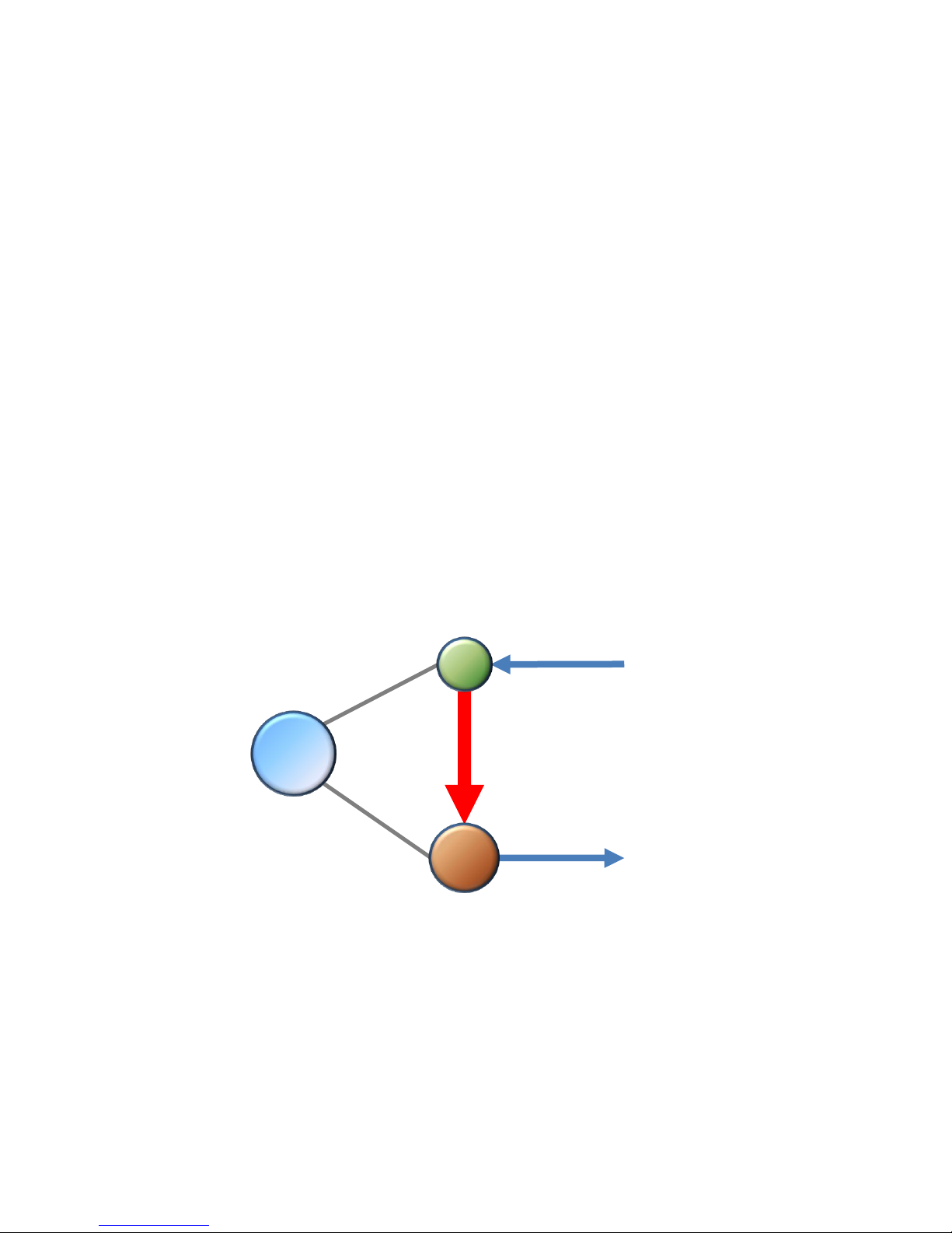
SERIAL
SERIAL
[7] Serial Data Transmission
from End Device to Router
Coordinator
Router
End
Page 69

• FZ200BS set to End Device enters into a low power consumption mode automatically
because it has a Target Device, and makes wake-up every once 10 seconds(default
setting time)
• You can not input any Serial Data while End Device is in a low power consumption Mode
• End Device can not receive wireless Data while the End Device is in a low power
consumption Mode
• If End Device is in a Low power consumption Mode, You need to work on the following in
order to input Serial Data(Please refer to the “FZx00_Appendix_3” for further details)
You can check End Device making wake-up at certain time, so you can input Serial
Data before the End Device enters into a low power consumption mode again.
If End Device doesn’t make wake-up by certain time, you should input KEY Data to
make End Device start wake-up forcefully. After that, you can input Serial Data
before the End Device enters into a low power consumption mode again.
< The following is a summary of End Device status >
Page 70
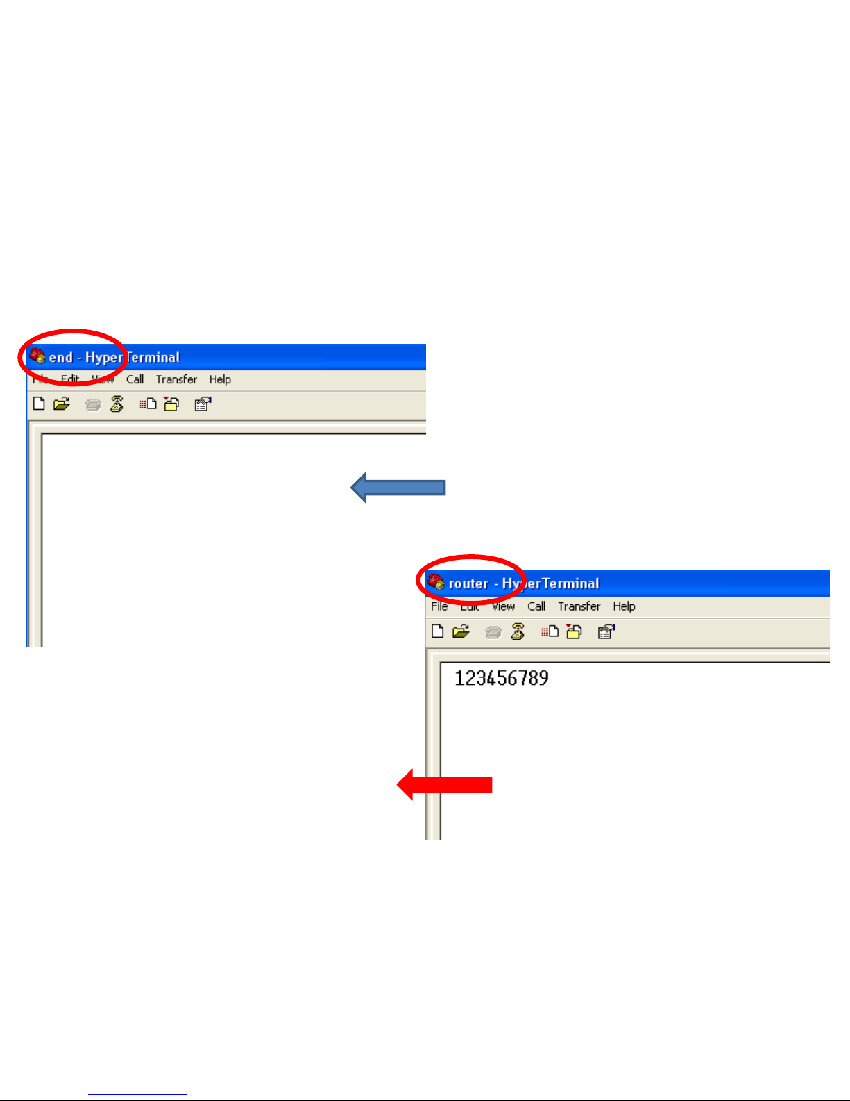
• Displays the followings on Hyper Terminal
connected to FZ200BS that is set to Router
• “123456789” is output
(1) Serial Data Input in End Device – Check in Router
After putting End Device in wake-up mode,
input the following into Hyper Terminal
connected to FZ200BS set to End Device
• After inputting “123456789” into Hyper
terminal, press Enter key
1. Serial Data Transmission “End Device -> Router”
Page 71
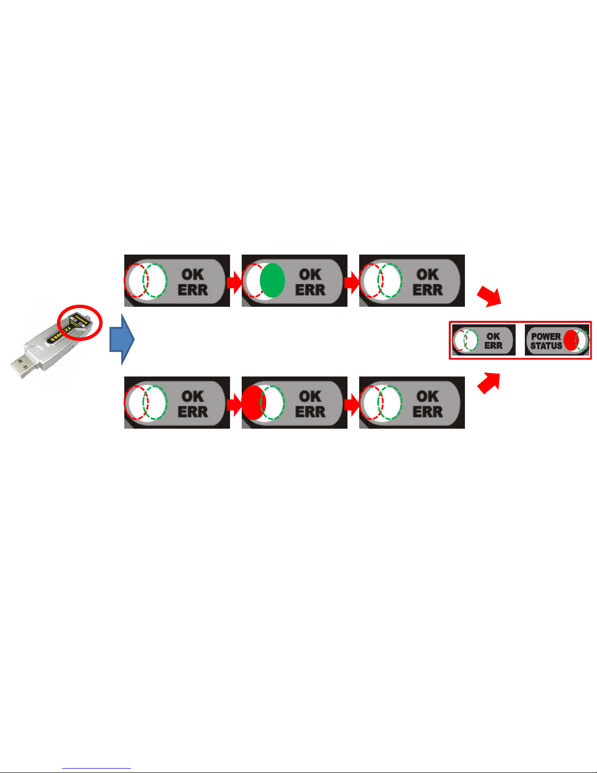
< Low power
consumption
mode >
OK/ERR LED conditions related ACK after Data transmission. (End Device)
< Case 1. ACK transmission is successfully done >
< Case 2. ACK transmission is failed >
• The Green OK LED blinks once if the Data transmission is successfully done.
• The Red ERR LED blinks once if the Data transmission is failed.
• End Device into the Low power consumption mode 1 second after ACK or NACK is
transmitted.
Page 72
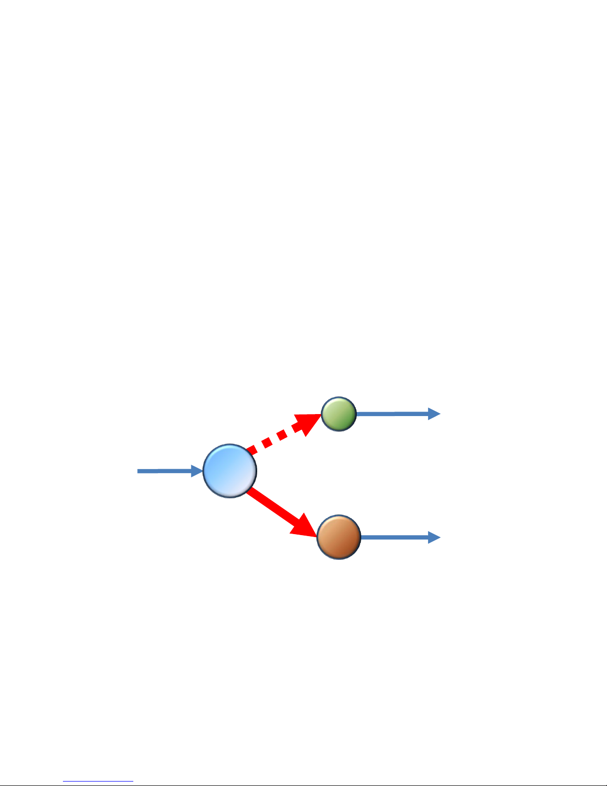
SERIAL
SERIAL
SERIAL
[8] Serial Data Transmission
From Coordinator to All devices
Coordinator
Router
End
Page 73
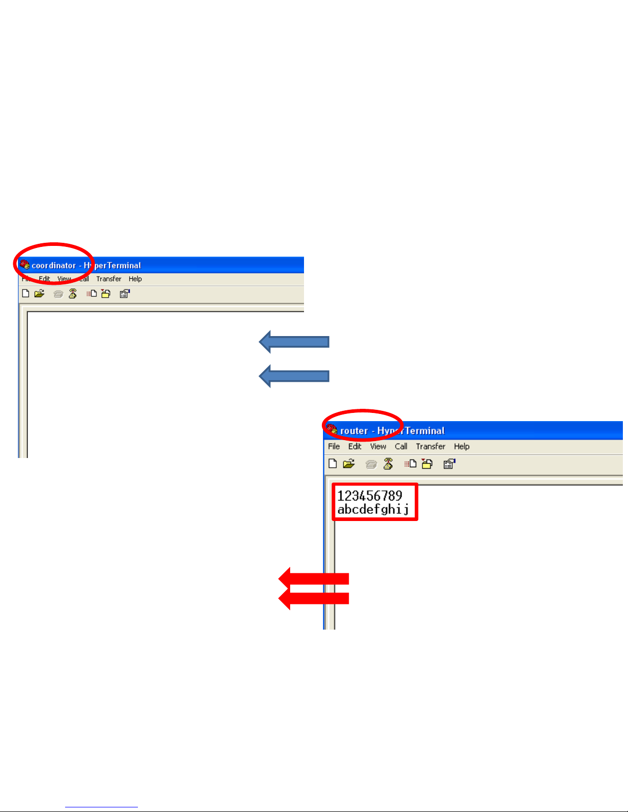
1. Serial Data Transmission “Coordinator -> ALL Device”
(1) Serial Data input in Coordinator – Check it in Router
• Input the following into Hyper Terminal
connected to FZ200BS that is set to
Coordinator
• After inputting “123456789” into Hyper
Terminal, press Enter key.
• After inputting “abcdefghij” into Hyper
Terminal, press Enter key.
• Displays the followings on Hyper Terminal
connected to FZ200BS that is set to Router
• “123456789” is output.
• “abcdefghij” is output.
Page 74

• FZ200BS set to coordinator transmits Serial Data to all Devices.
• However, FZ200BS set to End Device can not receive Data from Coordinator because
it is in a low power consumption mode.
• In order for End Device to receive Data while it is in a low power consumption mode,
you should put the End Device in a wake-up mode.
• If End Device receives wireless Data while it is in the wake-up mode, it outputs Data
to Serial port.
Page 75
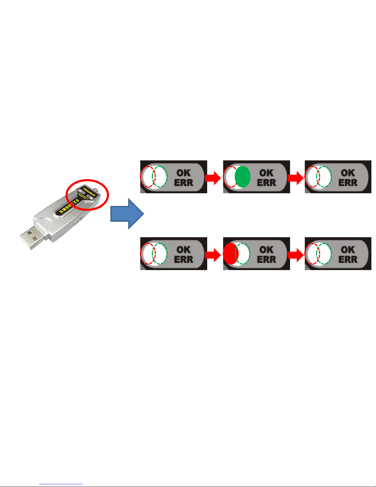
OK/ERR LED conditions related ACK after Data transmission. (Coordinator)
< Case 1. ACK transmission is successfully done >
< Case 2. ACK transmission is failed >
• FZ200BS set to Coordinator does not receive ACK when it transmits Data to all devices.
• FZ200BS set to Coordinator use OK/ERR LED to see if Data is transmitted by using wireless.
• The Green OK LED blinks once if Data transmission is successfully done by using wireless.
• The Red ERR LED blinks once if Data transmission is failed.
Page 76

Please refer to the FZ200BS manual for further details.
 Loading...