

TINY TNC-G10 Operation Manual
1
TNC-G10 Surface Grinder controller
Document: Operation Manual
Document #: T10
Document Rev: 1.0
Product: TNC-G10 Surface Grinder
controller
Product Rev: 1.0
Created: Jan, 2014
Updated: Jan, 2015
THIS MANUAL CONTAINS INFORMATION FOR INSTALLING AND OPERATING THE FOLLOWING
PRODUCT:
TNC-G10 SURFACE GRINDER CONTROLLER
“TINY CONTROLS” AND THE TINY CONTROLS COMPANY’S LOGO ARE COPYRIGHTS OF TINY
CONTROLS PVT. LTD. OTHER TRADEMARKS, TRADE NAMES, AND SERVICE MARKS OWNED OR
REGISTERED BY ANY OTHER COMPANY AND USED IN THIS MANUAL ARE THE PROPERTY OF THEIR
RESPECTIVE COMPANIES.
TINY CONTROLS PRIVATE LIMITED
C-55, NISHAT PARK, KAKROLA MOR, NEW DELHI, INDIA – 110078
WEB: http://www.tinycontrols.com
PHONE: +91-991-119-3210
Item
Page No.
GENERAL DESCRIPTION
3
SPECIFICATIONS/ FEATURES
3
LOCATION OF COMPONENTS
4
TERMINALS
5
OPRATING THE SURFACE GRINDER CONTROLLER
1. HOME SCREEN
2. JOGGING
3. SETUP SCREEN
6
7
7
MODES
1. SENSORS ENABLED
MODE 1
MODE 2
MODE 3
2. SENSORS DISABLED
MODE 1
MODE 2
MODE 3
8
8
8
9
10
11
11
12
13
BRIEF VIEW OF OPERATION
14
HOMING
15
SET UP MENU COMMANDS
16
EMERGENCY
17
CONNECTION DIAGRAM
18
CONTENTS
2
GENERAL DESCRIPTION
Tiny Controls’ surface grinder controller (SGC) is a new concept designed especially
for grinding operations. It is a versatile and economical solution designed to automate
the repetitive grinding tasks. It features automated longitudinal and cross feed. This
compact 2-axis surface grinding controller utilizes a simple and easy operating
interface and three selectable mode to help automate repetitive grinding tasks,
delivering the best results.
The following commands are supported: (see Setup section for more details)
Motion setup: M1Speed, M2Speed, M1Dir: CCW/ CW, M2Dir: CCW/ CW,
M1Accel, M2 Accel, M1HSpeed, M2HSpeed
Motion commands: M1Steps/ Rev, M2 Steps/ mm
SPECIFICATION/FEATURES:
Supply Voltage: 90V to 250V AC 50Hz/60Hz.
Max Pulse Rate: 40 KHz.
Overall Size: 165mm x 102mm x 76 mm.
Mounting: Panel mounts: 155mmx92mm.
Locomotion: Longitudinal (X) and Cross feed (Y).
Control:
Automatic mode select: 3 modes.
Manual mode select: 3 modes.
Jogging
Longitudinal and cross feed speed control.
Emergency stop.
Speed control by potentiometer
Inputs: 3 NPN Proxy (X limit, Y limit and Emergency input) + 1 On-Off switch
for start- stop.
Outputs: 2 for motor1 (STEP and DIR) +2 motor2 (STEP and DIR) +Two 12 V
outputs (for NPN proximity type sensor) +5 V (for POT connections).
Display: 20x4 LINES alphanumeric LCD.
Operating interface: User friendly keys.
Max Operating Temperature: 55 deg C.
3
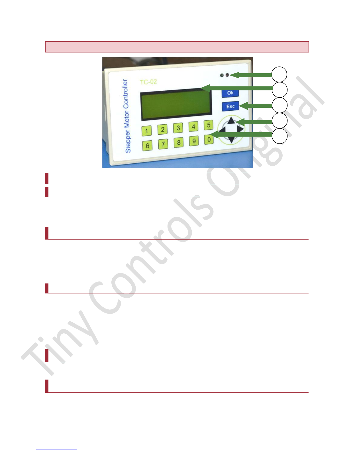
3 4 5 1 2
LOCATION OF COMPONENTS: Major components of the Controller
The description of these components is as following:
1. NUMERIC KEYS (0-9)
Numeric keys are used for entering the numeric values for manual limits in Jog screen
and entering values in Setup screen. These are also used to select the modes.
2. NAVIGATION KEYS PANEL (UP, DOWN, RIGHT, LEFT)
In Setup screen, these keys are used to navigate the cursor. However, in the home
screen, these keys are used to alter the speed and feed value. These keys are used
to jog the motor1 and motor2 in jog menu.
3. OK & Esc
OK: Press OK to enter in Setup screen from Home screen. In Setup screen, pressing
this key saves the modified values in EEPROM.
Esc: Press Esc to exit out of Setup screen. Press Esc key in home screen to enter in
jog screen.
4. LCD DISPLAY (20x4)
This LCD shows all the information related to MODES, Home and other screens.
5. LEDs
RED LED glows on homing and any activity. GREEN LED indicates long key press.
4
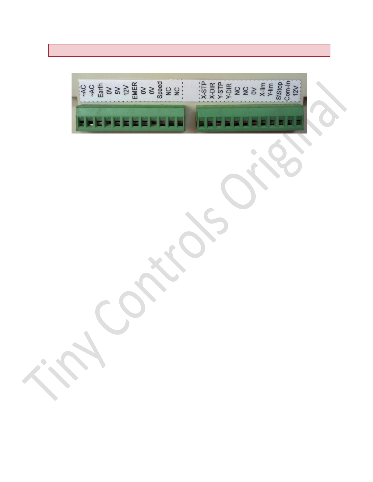
TERMINALS
REMOVABLE BLOCK TERMINALS:
PIN NUMBER
1. ~AC (90V to 250V AC 50Hz/60Hz Live, Handle with care).
2. ~AC (90V to 250V AC 50Hz/60Hz Neutral, Handle with care).
3. Earth (To Earth Main line, Handle with care).
4. 0V (Common ground, Connect to POT).
5. 5V OUTPUT (For POT connection).
6. 12V OUTPUT (For NPN type proximity sensors).
7. Emer- EMERGENCY INPUT (Connect output of N/O, NPN type proximity switch).
8. 0V (Common ground, For NPN type proximity).
9. 0V (Common ground, Connect to STEPPER DRIVER e.g. TSTEP-484).
10. Speed (Connect to center of POT for speed input).
11, 12. NC- not connected.
13. X-STP- STEP PULSE OUTPUT for motor 1, i.e. motor for X-axis (Connect to
STEPPER DRIVER eq. TSTEP-484).
14. X-DIR - DIRECTION output for motor 1, i.e. motor for X-axis (Connect to
STEPPER DRIVER eq. TSTEP-484).
15. Y-STP- STEP PULSE OUTPUT for motor 1, i.e. motor for Y-axis (Connect to
STEPPER DRIVER eq. TSTEP-484).
16. Y-DIR - DIRECTION output for motor 1, i.e. motor for Y-axis (Connect to
STEPPER DRIVER eq. TSTEP-484).
17, 18. NC- not connected.
19. 0 V (Common Ground).
20. X- LIM Connect output of NO, NPN type proximity switch).
21. Y- LIM (Connect output of NO, NPN type proximity switch).
22. Start- Stop: Connect the on- off switch here.
23. Com-In (Common for X-Lim and Y- Lim inputs, can be supplied external 12 volt or
jumped from 12v output from the controller).
24. 12V OUTPUT (For NPN type proximity).
5
OPERATING SURFACE GRINDING CONTROLLER
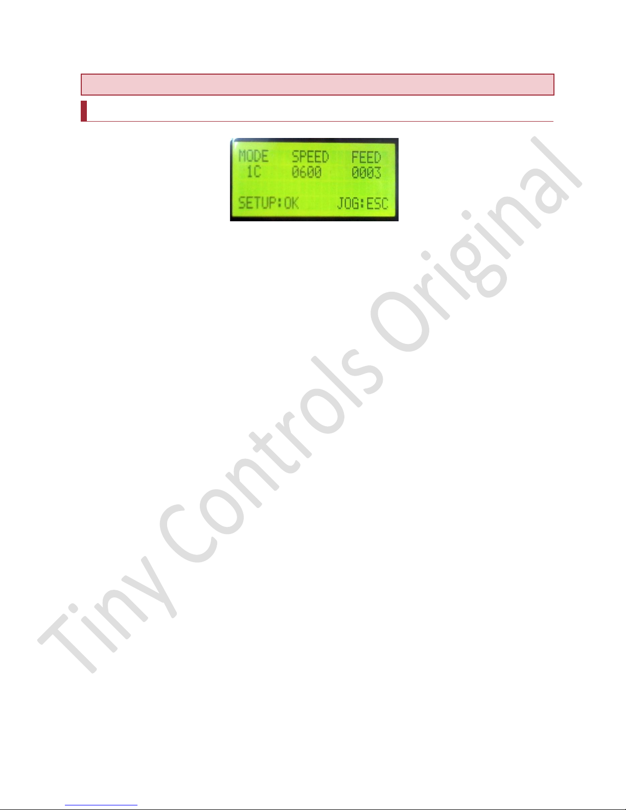
Home Screen:
When the power is applied to the board, a splash screen appears, after that the Home
screen appears. The user can change the modes by pressing the respective numeric
key. Stop or Continuous can be set along with mode by pressing key4. Speed can be
adjusted by using up-down navigation keys and feed can be adjusted using left- right
navigation keys.
The above specified three terms are described in the subsequent section.
NOTE: There is a homing feature available on key 8. If user presses key 8 on the
home screen, the motor moves to respective home position and searches for home
sensor input. The home speed can be adjusted in Set up screen for respective mode.
NOTE: If Emergency input is received anytime, the motion is halted and current
operation (even program run mode) is aborted. A message of emergency is displayed.
Press any key and the control will return to HOME screen.
MODES:
There are three modes that surface grinding controller supports. These are called as
mode 1, mode 2 and mode 3 respectively. However, mode can also be set as
continuous (C) or Stop (S).
Continuous (C): If continuous is set, the motor continues to rotate and repeats the
process after homing until the start key is pressed to stop the motors.
Stop (S): If stop is set, the motors stop after homing and rotate when the start key is
pressed to commence the motion.
6
 Loading...