

1
TIN KNOCKER
TK 2236 MANUAL ROLLS
INSTRUCTIONS & PARTS DIAGRAMS
121106 mod 1
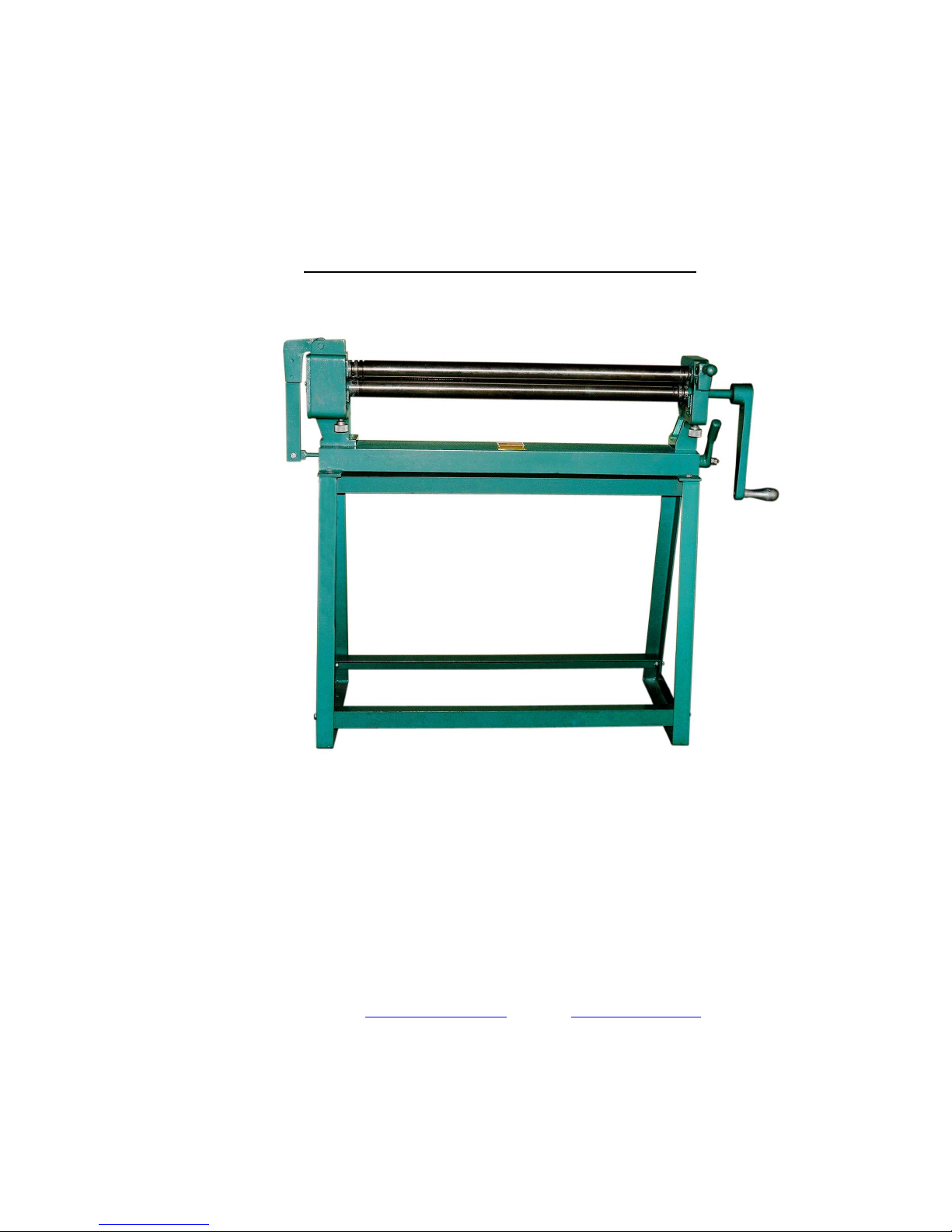
Shown with Optional Stand
TAAG MACHINERY CO.
(Master Distributor)
1257-B Activity Dr.
Vista, CA 92081
Tel: (800) 640-0746 Fax: (760) 727-9948
Website: www.tinknocker.com * Email: taag@sbcglobal.net

2
TIN KNOCKER
SAFETY RULES
TK 2236 MANUAL ROLLS
1. Never use a machine or tool for anything other than its intended purpose. Use the proper tool and
equipment for the task.
2. Do not remove, paint over, alter, or deface any machine-mounted warning and instruction plates
and signs.
3. Do not operate the machine in excess of its rated capacity 36” X 22 gauge.
4. Beware of protruding machine elements or assemblies. Avoid any pinch-points created by the
movement of the machine’s components.
WARRANTY
All new machines are sold with a one-year limited warranty, on factory defective parts. The warranty is limited to the original
user. TAAG Machinery Co. at its option, will repair, replace or refund the purchase price of any part, tool or machine that fails
during the warranty period. TAAG Machinery Co. will pay normal shipping charges for replacement parts. After 90 days from
date of purchase, all express or overnight delivery charges are the responsibility of the customer. Purchaser must deliver to
TAAG Machinery Co., at the address below, any written claim, with proof of original purchase. Replacement parts will be
invoiced to purchaser and credit issued when the failed part is delivered to TAAG Machinery Co. Removal, reinstallation or
replacement parts shall be at purchasers’ / user’s expense. Failure due to improper use of the machine voids the warranty.
NOTE: 1. This machine has been tested and adjusted prior to shipment, but can and often does require readjustment due to
vibration and bouncing during transport. Following the procedures described within can easily do readjustment. These are
procedures with which you, as a user, should be familiar, as you will use them repeatedly over the life use of the machine. If you
have difficulty in performing these procedures, we are here to support you. Call us at: (800) 640-0746.
2. Opening rolls (for Philipsburg Lock) are consumable items and not subject to warranty.
TAAG MACHINERY CO.
(Master Distributor)
1257-B Activity Dr.
Vista, CA 92081
Tel: (800) 640-0746 Fax: (760) 727-9948
Website: www.tinknocker.com * Email: taag@sbcglobal.net
We disclaim any responsibility whatsoever to the customer or to any other person for injury to person, or
damage to or loss of property or value, caused by any product which has been subjected to misuse,
negligence, or accident; or misapplied; or modified or repaired by unauthorized persons; or improperly
installed. We shall in no event be liable for any consequential damage, loss or expense arising from the use
of, or inability to use, our product.

3
Tin Knocker 2236 Rolls
Forming Machines, or Slip Roll Formers, are intended for rolling sheet metal or forming cylinders of
various diameters.
The two pinch rolls feed the sheet against the rear roll, curving the sheet and forming the cylinder. The
rear or forming roll can be adjusted by screws on the rear of left and right end housings, varying the
diameter of the required cylinder. Pinch rolls can be adjusted for stock thickness by screws on front of end
housings.
The capacity ratings of Tin Knocker forming machines are based on forming mild steel, fully annealed, the
full length of the rolls and are considered as standard by the sheet metal trade for forming rolls of a
specified diameter and length. Definite capacities, however, depend upon the diameter and length of
cylinder to be formed and the number of passes through the rolls to obtain a given diameter. Stiffness of
material and uniformity desired are also factors. When a forming machine is overloaded, the immediate
result will be deflection in the center of the rolls, resulting in cylinders bulged in the center.
In order to reduce the number of rear roll adjustments when sheets are of light gauge, proceed as follows:
1) Insert the sheet between two pinch rolls.
2) Bend the sheet upwards and slightly around the top roll.
3) Continue to pass the sheet through the machine.
This will also reduce the flat spot on the leading edge of the sheet.
The right-hand housing is provided with a hinged journal cap and lifting latch. After the cylinder is
formed, the latch is lifted and the lever is pressed down. This raises the top roll and the cylinder can be
slipped off the roll without distortion.
Forming machines are provided with grooves in the right end of the lower and rear rolls to allow for
forming cylinders with a wired edge.
WARNING: Before operating, machines must be bolted to work bench. If floor stand
has been provided, machine must be bolted to floor stand with bolts provided. Stand must be
securely lagged to floor.

4
INSTRUCTIONS
CAUTION: Be sure that the machine is securely bolted onto pedestal or to customer
supplied bench. Pedestal or workbench should be bolted to floor.
1. Adjust Lower Roll (11) to grip the metal firmly and evenly but without straining the machine. Lower
Roll (11) is adjusted up or down with the two lower Adjusting Screws (29).
2. Adjust Rear Roll (12) to form the metal up as it travels through the rollers. Rear Roll (12) is adjusted
up or down with the two rear Adjusting Screws (22). Be sure Rear Roll (12) is parallel with Lower
Roll (11). If rolls are not parallel, the formed metal will be conical in shape instead of cylindrical.
3. Feed the stock to the rolls only from the front.
4. As the front rolls grip the stock, lift the rear end of the metal upward. This will help reduce the flat spot
on the leading edge of the sheet and will also cause the leading edge to pass over the rear roll readily.
5. The diameter of the formed cylinder is determined by the position of the Rear Roll (12). To increase
the diameter of a cylinder, lower Rear Roll (12) by turning the two-rear Adjusting Screws (22) counter
clockwise. To reduce the diameter of a formed cylinder, raise Rear Roll (12) by turning the two rear
Adjusting Screws (22) clockwise. The two rear Adjusting Screws (22) should be turned an equal
number of turns in order to keep the Rear Roll (12) parallel with the front gripping rolls.
6. To remove a cylindrical piece without distorting it, lift up Locking Handle (27), raise Right Hand
Housing Cap (1/2) and turn Cam Handle (15) down. This raises the outboard end of the Upper Roll
(10) and allows the formed cylinder to be slipped off of the Upper Roll (10).
7. The Lower Roll (11) and the Rear Roll (12) have grooves of varying widths in one end. These are for
the purpose of accommodating a wired edge when forming a shape or when forming wire into a ring.
8. "X" points should be lubricated daily with a good grade machine oil. "Y" points should be greased
weekly with Alemite #33 or equal.

5

6
VIEW A-A

7
Fine No.
Part No.
Description
No. REQ"D.
1 ROLL001 Lift Lever 1
2 ROLL002 Cover Plate 1
3 ROLL003 Bolt M8 x 25 2
4 ROLL004 Bolt M10 x 40 2
5 ROLL005 Rocking Box 1
6 ROLL006 Set Screw M6 x 25 3
7 ROLL007 Roll Gears 2
8 ROLL008 Rocking Box Pin 1
9 ROLL009 Box 4
10 ROLL010 Upper Front Roll 1
11 ROLL011 Lower Front Roll 1
12 ROLL012 Rear Roll 1
13 ROLL013 Crank Assembly Handle 1
14 ROLL014 Jam Nut 2
15 ROLL015 Cam Handle 1
16 ROLL016 Bolts M12 x 40 5
17 ROLL017 Cam 1
18 ROLL018 Machine Base Assembly 1
19 ROLL019 Left Hand Housing 1
20 ROLL020 Cam Rod 1
21 ROLL021 Bolt M10 x 30 1
22 ROLL022 Adjusting Screw Long 2
23 ROLL023 Right Hand Housing 1
24 ROLL024 Pin 16 1
25 ROLL025 Cap Right Hand Housing 1
26 ROLL026 Pin 12 1
27 ROLL027 Locking Handle 1
28 ROLL028 Locking Handle Screw 1
29 ROLL029 Adjusting Screw Short 2
Parts For 2236 ROLLS
 Loading...