

Page 1

Tel: (909) 890-0700 Fax: (909) 890-0736
P. O. BOX 1667 SAN BERNARDINO, CA 92402-1667
Web: www.tinker-rasor.com E-mail: Info@tinker-rasor.com
- 1 -
Sponsoring members of NACE International, NACE Foundation
PRODUCT INSTRUCTIONS
QMF-570 112-072
Model XL-2 - Fluid Leak Detector
Model XL-2 Includes:
(A) Instrument
All controls and connections are
made with the instrument, using the control
panel. The instrument is housed in a rugged
outdoor use thermoplastic resin case. It is
water tight, has a latching lid, and can be
locked. The case also has a storage area to
hold accessories. The Panel and Controls
are explained in more detail in Section 2 –
Control Panel.
(B) Pickup w/ Cable
The Pickup is the sensor
microphone which is set on the ground
surface to pick up the acoustic signals of the
leak. It has three small spike feet to help
make good contact with most surfaces. It is
designed to be moved to locate the strongest acoustic signal. More on the Pickup is explained
later in Section 3 – Operation
(C) Probe spike
The probe spike is an additional part of the Pickup which can be screwed into the
bottom of the Pickup sensor to enhance the signals reception. The probe is used when the
ground cover is soft dirt, or turf and the probe can be pushed into the ground. It can also be
used to make direct contact with the pipe.
(D) 9v Battery (Installed, not shown)
A common 9v battery operates the XL-2 instrument. There is a battery holder on
the panel which can slide up and out, making battery changes simple. More on the battery in
Section 6 – Servicing.
(E) Headphones
The included headphones are over ear style headphones, designed for comfort
and to assist in blocking out environmental noises and distractions. The headphones are
specific to the XL-2. More on headphones is explained later in Section 2 - Components.
Figure 1 Model XL-2 Kit
Page 2
Tel: (909) 890-0700 Fax: (909) 890-0736
P. O. BOX 1667 SAN BERNARDINO, CA 92402-1667
Web: www.tinker-rasor.com E-mail: Info@tinker-rasor.com
- 2 -
Sponsoring members of NACE International, NACE Foundation
PRODUCT INSTRUCTIONS
QMF-570 112-072
(F) Instructions (Not Shown)
These instructions are shipped with each new XL-2 instrument. Instructions can
also be downloaded for the Detectron website: www.detectron.com, or by contacting Tinker &
Rasor.
(G) Warranty Card/Calibration Statement (Not Shown)
The XL-2 comes with a limited 1-year manufacturer warranty against defects in
manufacturing. If you experience problems with the XL-2 instrument, first contact Tinker &
Rasor for technical assistance by calling our offices, or e-mailing: Support@tinker-rasor.com.
1. UNPACKING
Note the various components included with the instrument and store them in the same
location when not in use. When unpacking the instrument, ensure all items have been
received. If there is any damage to the shipping carton, you may need to make a claim with the
carrier. The included 9v battery is installed in the instrument.
Locate the warranty card and follow directions to register your product online.
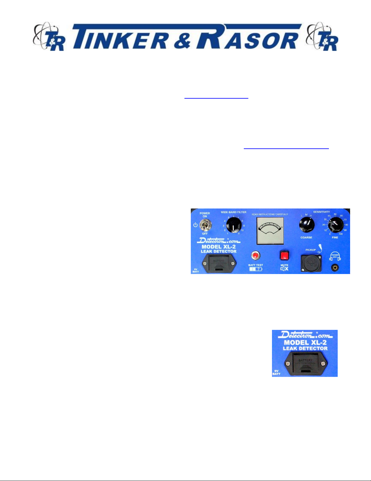
2. COMPONENTS
Control Panel
The XL-2 Control Panel is the main interface to
control the features and performance of the
instrument.
Power
The XL-2 instrument is powered On and
Off by a toggle switch, located in the upper
Left corner of the Control Panel. When powered On, the LCD display will show and briefly
display full bars. When turned Off, the XL-2 is disconnected from the 9v power source and can
be stored indefinitely. If the unit is to be stored for a longer period, > 6 months, the 9v battery
should be removed from the instrument. See more on the Battery, below.
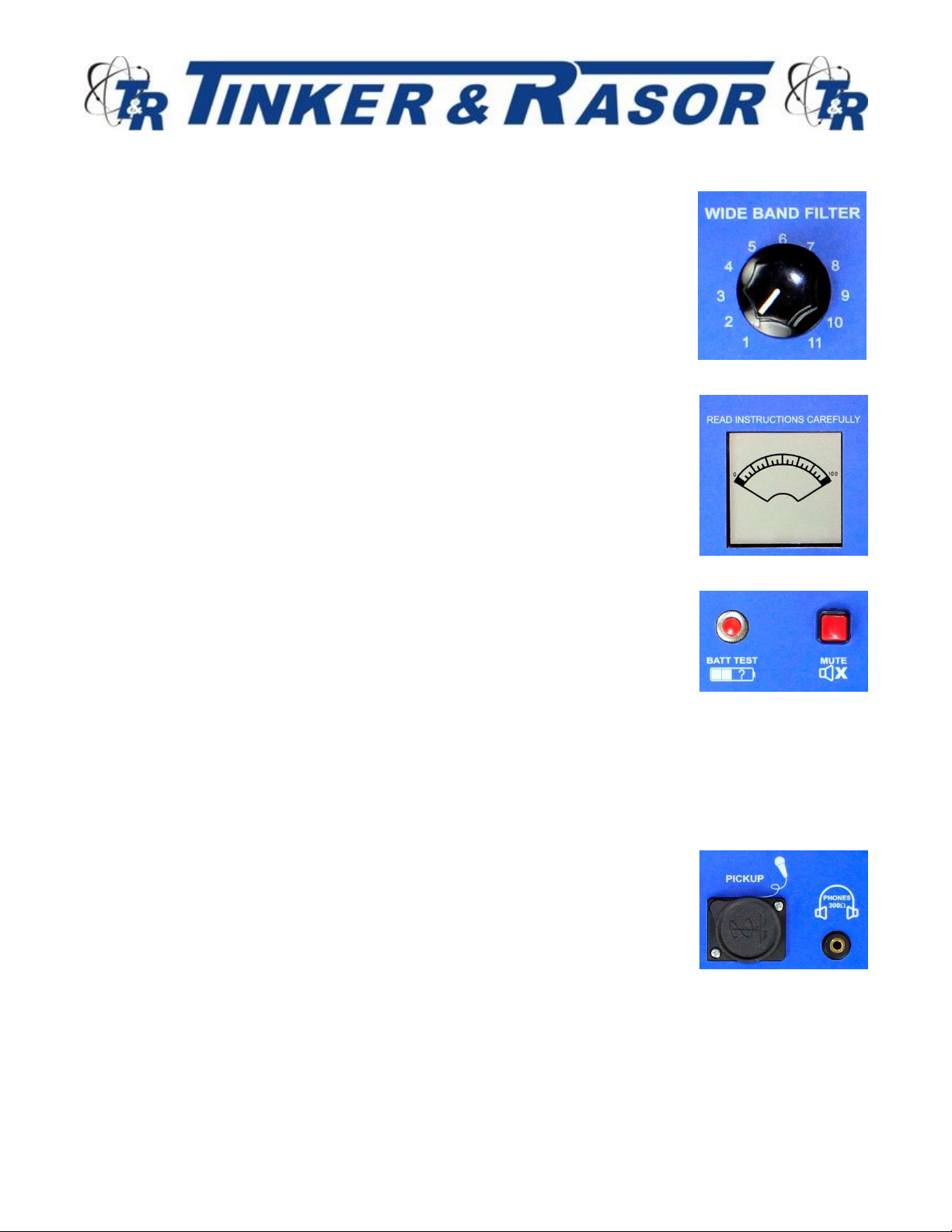
Battery
The XL-2 is powered by a single 9v battery. The common 9v
battery is easy to find and replace, and the instrument does not require
any charging. It will always be ready to use when you need it.
The Batt Test button should be used periodically to ensure the
battery is in good condition. When using the Batt Test button, ensure
that the headphones and Pickup are both plugged into the instrument.
When the battery is too low, the LCD will fade out.
Figure 2 Control Panel
Figure 3 Battery Holder
Page 3
Tel: (909) 890-0700 Fax: (909) 890-0736
P. O. BOX 1667 SAN BERNARDINO, CA 92402-1667
Web: www.tinker-rasor.com E-mail: Info@tinker-rasor.com
- 3 -
Sponsoring members of NACE International, NACE Foundation
PRODUCT INSTRUCTIONS
QMF-570 112-072
Filter
The XL-2 has an 11-position filter switch. The filter is used to
accentuate the sound of the leak while lessening or removing other
environmental sounds. This lets the user focus in on just the sound of
the leak. It is suggested to always start with no filter selected by pointing
the switch straight down at the six o’clock position. When a leak is heard
and sensitivity has been adjusted you can begin selecting filters. More
on the use of the Filter is explained later is Section 3 – Operation
LCD
The main LCD display shows a digital representation of an analog
swing meter. The meter displays a series of dark lines from Left to Right.
As these lines move to the Right of the display, they are indicating more
acoustic signal being received. The display is meant to mimic or be the
visual representation of the intensity of the audible signal being received
by the headphones. The LCD will flash to indicate a low battery voltage.
Batt Test
The panel of the XL-2 includes a momentary button to test the
battery. When this button is pushed, the LCD display changes to show
the battery level, and is no longer displaying signal intensity. When the
button is released, the LCD goes back to signal intensity. This button
only functions when held down. The performance of the instrument can
be affected by low battery voltage.
Mute
The Red Mute button is a latching switch. When depressed and released, the mute
feature is on and the audible signal to the headphones is cut off. Pushing and releasing the
button again will turn the mute feature off.
Pickup Connector
The Pickup connects to the XL-2 panel at the Pickup connector.
The Pickup connector has a cover to keep water and debris out of the
instrument when the Pickup is not connected. The cover is rotated to
allow the Pickup cable connector to mate with the instrument panel. The
Pickup cable has a 3-pin connector. It is pushed into the panel Pickup
Connector firmly and should be pushed down until it stops, ensuring a
good connection.
Figure 4 Filter Selector Switch
Figure 5 LCD Display
Figure 6 Batt Test & Mute
Figure 7 Pickup & Headphones
Connection
Page 4

Tel: (909) 890-0700 Fax: (909) 890-0736
P. O. BOX 1667 SAN BERNARDINO, CA 92402-1667
Web: www.tinker-rasor.com E-mail: Info@tinker-rasor.com
- 4 -
Sponsoring members of NACE International, NACE Foundation
PRODUCT INSTRUCTIONS
QMF-570 112-072
Headphone Jack
The headphones connect to the panel at the headphone jack. This connector is a
standard 3.5mm headphone jack, and will accept a wide variety of headphones.
The headphones included with the XL-2 are specifically designed for use with the instrument
and have an impedance of 300 Ohms (each ear piece), which make
them a superior choice for this application. Use of other impedance
headphones is not suggested, and will likely result in poorer
performance than the using the included headset.
Headphones have a standard fit adjustment for each ear piece and also
have a volume control adjustment on one side.
Sensitivity – Coarse
The Coarse Sensitivity adjustment switch can be rotated between
three options: Low (L), Medium (M) and High (H). More on the use of the
Sensitivity controls later in Section 3 – Operation
Sensitivity – Fine
The Fine Sensitivity adjustment switch is rotated from 0 to 100 to
increase the sensitivity of the Pickup signal. More on the use of the
Sensitivity controls later in Section 3 – Operation
Storage
The XL-2 control panel is bent to allow for in-case storage of
accessories such as the Pickup and Probe.
Pickup
The pickup sensor is made up of the main pickup body, the attached
cable and the optional probe. The probe can be screwed into the pickup
body. More on the pickup and probe in Section 3 – Operation
3. OPERATION
Setup in the area where you will begin the leak detection.
• Open the case and make the connection of the Pickup cable to the control panel.
• Screw the Probe spike into the Pickup, if it is to be used.
• Place the Pickup on the ground area where you will begin detecting.
• Connect the headphones to the headphone jack on the panel
• Turn the XL-2 On by moving the toggle switch up to Power On.
• Note the LCD becomes active. Push the Batt Test button to ensure good battery
condition.
Figure 9 Sensitivity Controls
Figure 8 Headphones
Figure 10 Pickup & Probe.
Page 5

Tel: (909) 890-0700 Fax: (909) 890-0736
P. O. BOX 1667 SAN BERNARDINO, CA 92402-1667
Web: www.tinker-rasor.com E-mail: Info@tinker-rasor.com
- 5 -
Sponsoring members of NACE International, NACE Foundation
PRODUCT INSTRUCTIONS
QMF-570 112-072
• Rotate the Filter switch all the way counter-clockwise so that the knob is pointing down,
towards the six o’clock position. No filter selected.
• Rotate the Coarse Sensitivity switch counter-clockwise to position L.
• Rotate the Fine Sensitivity switch counter-clockwise to position 0.
• Put on the headphones. You should immediately note the sounds from the Pickup.
• Press the Mute button to disengage the headphones.
NOTE: As you move the Pickup from one location to the next, it is suggested that you mute, in case the very
sensitive Pickup is bumped or banged into something creating a very loud condition in the headphones.
You are ready to begin the leak detection survey.
With the Pickup placed on the surface to be investigated, begin to adjust the "COARSE"
and "FINE SENSITIVITY" controls. Starting at the COARSE setting L, adjust the FINE setting
knob clockwise. If leak is not heard, or is not loud, move COARSE setting to M, and start FINE
setting at 0 again. If necessary, move COARSE to H, and adjust FINE from 0 again. Move the
sensitivity controls until the meter indicates somewhere in the upper two-thirds of its scale and
note the sounds heard in the headphones. If a leak is heard, the filter switch may be rotated to
a position which accentuates the leak and reduces background noise. Filters 1 through 11.
When moving the Pickup or during periods of excessively high background noise, it is possible
to mute the detector without disturbing the sensitivity controls by pushing the MUTE button on
the control panel.
When listening for sounds on an exposed pipe, screw the pointed probe into the bottom of the
Pickup and hold the point firmly against the pipe. Underground leaks can often be detected
more easily by pushing the pointed probe into the ground. When listening for leaks on flat
surfaces, the probe is removed, and the Pickup is placed on the surface with the three spikes
supporting it.
It is possible to familiarize oneself with the sound of a water leak by listening on a water line
and slowly turning on a faucet so that a small amount of water is discharging from it. By
alternately turning the water "on" and "off" the characteristic high-pitched hissing sound can be
heard and distinguished from other sounds on the line.
4. LEAK DETECTION METHODS
The general locality of the water leak may be indicated by a metered loss, damp spots, or
surface water. Since water from an underground leak usually travels a considerable distance
before appearing at the surface its presence usually only indicates the general area of a leak.
To narrow down the search for the leak, take readings with the leak detector on all exposed
portions of the system (fireplugs, meter boxes, valves) in the suspected area. When taking
Page 6

Tel: (909) 890-0700 Fax: (909) 890-0736
P. O. BOX 1667 SAN BERNARDINO, CA 92402-1667
Web: www.tinker-rasor.com E-mail: Info@tinker-rasor.com
- 6 -
Sponsoring members of NACE International, NACE Foundation
PRODUCT INSTRUCTIONS
QMF-570 112-072
comparative readings with a leak detector, all readings must be made to the same reference
level if accurate results are to be obtained. After the first reading is taken and the sensitivity
controls have been initially set, subsequent readings should be taken without re-adjusting the
sensitivity settings, so that the deflection of the meter will give a true indication of relative
sound intensities.
Another method of taking comparative readings is to adjust the "FINE SENSITIVITY" control
until some particular meter reading (say one-half scale) is obtained. Record the position of the
sensitivity control required at each location to give the same meter indication. If more
sensitivity is required at a subsequent location, the leak sound is weaker, and if less sensitivity
is required, the leak sound is greater.
After determining the specific area of the leak from readings taken on exposed portions of the
system, the next step is to pinpoint the leak. First, mark the course of the pipeline including all
laterals and services using a Detectron Model 505 "Go-Fer" Pipe & Cable Locator. Take
readings every few feet along the course of the suspected pipeline by placing the pickup on
the surface directly over the pipe and record the sound intensity. Correlation of these readings
will indicate the exact location of the leak.
5. OPERATING SUGGESTIONS
1. Protect the pickup and its cable from wind. Wind noise is likely to mask the sound of a leak.
2. Use systematic approach to leak locating. Always know the exact location of the suspected
pipeline.
3. Become familiar with the sound produced by a water leak by experimenting with known
leaks.
4. Whenever possible, use the same personnel for leak detection work. Experience is a great
aid to efficient leak locating.
5. When the leak sound has been located on the main, be sure to check for unknown laterals
which may have leaks.
6. SERVICING
To replace battery, slide the battery holder up and out of the control panel. To open the battery
holder, insert a finger nail or small standard screwdriver into the slot opening near the bottom
of the battery holder. Push the holder up towards the Detectron logo and lift up and away from
panel. The battery holder and 9v battery will come completely away from the instrument, with
no wires attached. Replace the 9v battery and pay close attention to polarity. The battery
holder has a large opening and a small opening. Ensure that the battery contacts match the
size of the openings.
Page 7

Tel: (909) 890-0700 Fax: (909) 890-0736
P. O. BOX 1667 SAN BERNARDINO, CA 92402-1667
Web: www.tinker-rasor.com E-mail: Info@tinker-rasor.com
- 7 -
Sponsoring members of NACE International, NACE Foundation
PRODUCT INSTRUCTIONS
QMF-570 112-072
All 9v batteries are not equal in energy and performance. 9v batteries can range from 400 mAh
to 1200 mAh and the performance of the XL-2 will match the battery installed in length of
battery life. Rechargeable 9v batteries are not recommended for use in the XL-2.
If the detector fails to operate properly, be sure all controls are set to the proper positions.
Make sure the mute button is not set. Ensure the headphones and pickup are connected.
Check the connections for faults or breaks.
7. SHIPPING INSTRUCTIONS
All instruments being returned for repair should be sent PREPAID to either address below:
Via courier (UPS, FedEx, DHL, etc)
Tinker & Rasor
ATTN: Repairs
791 S. Waterman Ave
San Bernardino, CA 92408
Via US Postal Mail
Tinker & Rasor
ATTN: Repairs
P.O. Box 1667
San Bernardino, CA 92402-1667
Include with shipment information the nature of the problem, purchase order, serial number
and return delivery address and phone and fax numbers.
A fill and print repair form is available on the Tinker & Rasor website: www.tinker-rasor.com
Look for the link to Repairs under the Contact Us menu.
110-317
Model XL-2 Parts List
QTY
Part Number
Description
01
085-165
Instrument, XL-2, with battery
01
010-007
Battery, 9v
01
122-001
Pickup, with cable and probe
01
118-001
Probe, 7” spike for XL-2
03
073-017
Spike, small, dirt. For XL-2 pickup
01
115-004
Headphones, 300 Ohm impedance, 3.5mm with ¼” adapter
 Loading...