

Page 1
CORROSION MITIGATION INSTRUMENTATION
P. O. BOX 1667 SAN BERNARDINO, CA 92402 TEL: (909) 890-0700 FAX: (909) 890-0736
PRODUCT INSTRUCTIONS
MODEL M/2
WET SPONGE HOLIDAY DETECTOR
Unpacking Checklist
The Model M/2 Holiday Detector Kit includes the following:
(1) Model M/2 Unit (085-156)
(1) Battery, 9v (010-007)
(1) Cable, Ground (026-101)
(1) Water Wetter Solution, 4oz (049-013)
(1) Wand, 16” (177-070)
(1) Sponge Assembly (ships assembled)
(1) Sponge (055-882)
The information contained in this document is subject to change without notice and does not represent a
commitment on the part o f Tinker & Rasor.
(1) Holder, Yellow (076-050)
(1) Knob, sponge holder (094-030)
(1) Sponge bracket (014-195)
(1) Canvas tote bag
(1) Screwdriver
(1) Instructions
(1) Warranty/Calibration Document
Any and all reproduction or transmission of any part of this manual, in any form or by any means and for
any purpos e other than the personal use by the purchaser is strict ly forbidden without the e xpress written
authorization of Tinker & Rasor.
For updates, please visit our website:
http://tinker-rasor.com
© 2018 Tinker and Rasor, Inc.
All rights reserved.
Web: www.tinker-rasor.com E-mail: Info@tinker-rasor.com
Page 1 of 6
Page 2

CORROSION MITIGATION INSTRUMENTATION
P. O. BOX 1667 SAN BERNARDINO, CA 92402 TEL: (909) 890-0700 FAX: (909) 890-0736
PRODUCT INSTRUCTIONS
DESCRIPTION
The Model M/2 H ol id a y De t ec tor is a highly sensitive d evic e d es igned to locate holid a ys ( pi n hol es, voids ,
etc.) in thin film protective coatings of relatively high electrical resistance when such films are applied to the
surface of mater ial of low e lectric al res istance . In t hese ap plic ations, s uch as pai nted m etal sur faces , the
Model M/2 Holiday Detector will locate these points very accurately with an audible and visual signal. This
method of inspection of thin film is a non-destructive test and will not injure the protective coating.
OUTPUT VOLTAGES
The M/2 has multiple volta ge outputs tha t can be sele cted. T hese outputs hav e been deter mined to meet
varying international standards regarding the use of the equipment. The Model M/2 Low Voltag e (Wet
Sponge) Holiday Detector is designed to meet or exceed the requirement of the following standards (Partial
List):
NACE RP0188, SP0188, TM0384
ASTM D 5162-A, G6, G62-A
ISO 8289, 14654, 14655, 14656, 15741, 16967, 29601
AUSTRALIA AS 3894-2
JAPAN JIS 6766
EQUIPMENT
The Model M/2Holiday Detector consists of a portable battery powered electronic instrument, a wand
handle, and sponge assembly (open ce ll sponge ships c ompressed, will expand with water), and ground
wire. The instrument is housed in a sturdy plastic case with provision for attachment of optional (not
included) headphones .
The detector is a “non-d estructive wet sp onge” type holida y detector. The b asic electronic des ign of the
Model M/2 Holiday Detector is that of a ver y sensiti ve circ uit whic h is ener gized by on e 9 v batter y. When
current of 500 or 700 (+/- 10/%) micro-amperes flows in the circuit, an audible and visual signal is actuated.
The test lead wire used in the ground wire can handle a minimum of 100 milliamps at 100 volts. If
replacement or addit ional wire is need ed, make sure it m eets these requirem ents. Up to 100’ len gth of
ground wire does not ad versely affec t the detectors oper ation, in mos t cases. If adding add itional ground
wire, 14 AWG stranded or equivalent is recommended.
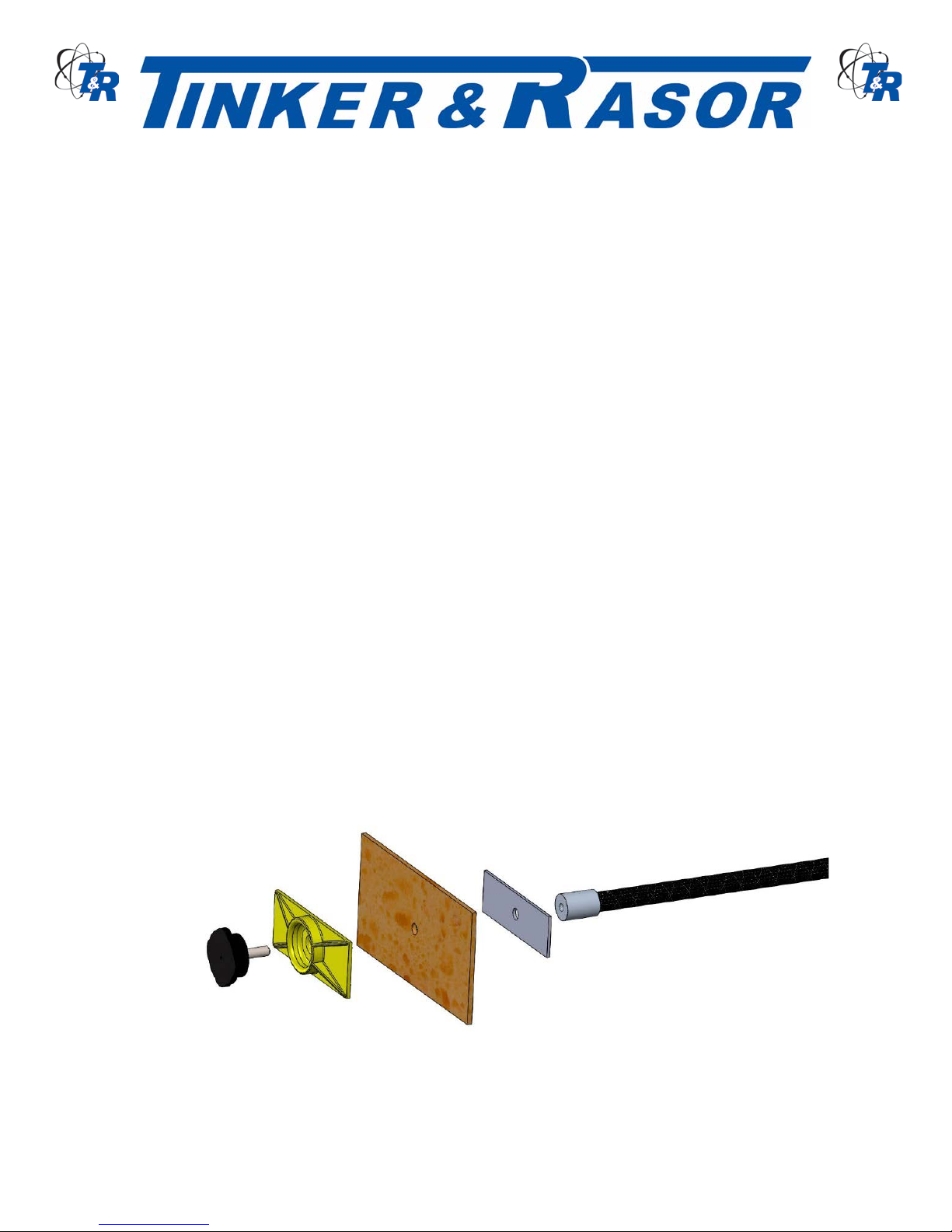
The exploring electrode is open-cell sponge material and is conductive when saturated with a wetting
solution. The sponge electrode is attached to the non-conducti ve wan d hand le b y means
of the bolt with knob, plastic sponge holder and backing plate.
The wetting solution should consist of potable tap water and a wetting agent.
The ratio of one (1) ounce agent t o one (1) gal lon tap wat er is recomm ended. Tinker & R asor WATER-
WETTER© is a non-sudsing wetting agent, av ailable in 8 oz. bottles, f actory direct or through s tocking
distributors.
Web: www.tinker-rasor.com E-mail: Info@tinker-rasor.com
Page 2 of 6
Page 3

CORROSION MITIGATION INSTRUMENTATION
P. O. BOX 1667 SAN BERNARDINO, CA 92402 TEL: (909) 890-0700 FAX: (909) 890-0736
PRODUCT INSTRUCTIONS
PRE-ELECTRICAL TEST PROCEDURES
The protective coatings should be dry and free of all contamination prior to electrical holiday testing. Proper
curing and drying tim e of the protec tive coating m ust be establ ished prior to c onducting e lectrical hol iday
testing.
Note: Solvents retained in the protective coating f ilm can cause erroneous indications (false holida ys)
during electrical testing.
The dry film thickness should not exceed 20 mils when electrical holiday testing is done with the low voltage
Model M/2Holiday Detector. Film thickness should be determined with a non-destructive dry film thickness
gauge to make sure limits are not exceeded.
Special Note: Ordinary tap water will generally suffice to dampen the sponge electrode, provided
the protective coating thickness does not exceed 10 mils. The factory recommended practice is
to use a wetting agent at all times, regardless of coating thickness up to 20 mils. The low voltage
holiday detector is not recommended for coatings greater than 20 mils of thickness.
Check battery voltage. This can be done by shorting the wet sponge with the bare end of the ground cable
of the holida y detector . If a steady, level au dibl e si gnal is heard, th e battery voltage is OK. If the aud ible
signal starts to attenuate while testing, REPLACE battery. Note: A battery output voltage drop of over 10%
also indicates weak batter y.
HOLIDAY DETECTOR ASSEMBLY
Assemble the Holiday Detector b y first connecting the ground cable to the h and le. Ins er t the gr oun d cable
connector into the han dle, and then rotate one quarter tur n counter clock wise to lock. Connect the wand
handle to the front (nose) of the instrument and screw down until firmly seated.
Attach the sponge bracket (aluminum piece), sponge, sponge holder (plastic piece) and the knob with
threaded bolt through all and screw down on the wand end. Saturate the sponge in a wetting solution.
CALIBRATION
Factory calibra tion o n Mod el M/2 Holiday Detectors is for the voltages and resist ances of eac h of the f our
(4) output settings. All voltages are calibrated to a tolerance of +/- 5%.
Web: www.tinker-rasor.com E-mail: Info@tinker-rasor.com
Page 3 of 6
Page 4

CORROSION MITIGATION INSTRUMENTATION
P. O. BOX 1667 SAN BERNARDINO, CA 92402 TEL: (909) 890-0700 FAX: (909) 890-0736
PRODUCT INSTRUCTIONS
USING THE M/2
The Model M/2 is turned ON by pressing the Power On/Off button on the instrument panel. When powered
On, the M/2 will f lash the Blue LEDs through each of the four (4) outp ut voltages. Once th e LED’s flash
through once, the LED will indicate the selected output voltage.
A Low Battery cond ition exis ts when all f our (4) of the Blue LEDs continue to f lash. T he 9v b atter y shoul d
be replaced when this indication occurs.
MAIN PANEL AND LED INDICATORS
The main instrument panel includes t wo (2) butt ons an d f ive (5) LED indicators. The RED LED indic ates a
holiday signal. This LED will light along with the audible tone indicator of a holiday.
The four (4) output voltage settings each have an as sociated LED. The LED that is illuminated in dicates
the output voltage of the M/2.
ADJUSTMENT OF THE OUTPUT VOLTAGES
Model M/2 Holiday Detector offers four (4) output voltages and sensitivity settings.
9v @ 90 K-ohms
67.5 volts @ 80 K-ohms
67.5 volts @ 90 K-ohms
90 volts @ 400 K-ohms
When the M/2 is powere d O n, the Bl ue LED will ind icate th e selec ted vo ltage o utput. Pres sing the Outpu t
Voltage button will change the voltage selection, and a Blue LED will indicate the new output voltage.
Consult with the coatin g manufacturer, inspector or t he standard being refer enced for the application to
determine which output volt age is suggested.
CHANGING THE BATTERY
The M/2 is powered by a repl aceable 9v batter y. To acces s
the battery, locate the BATTERY ACCESS label on the main
top panel of the instrument. There are two (2) screws near
the handle that need to b e r em oved. Once removed, lif t and
rotate the BATTERY ACC ESS door toward the front of the
instrument and remove. Replace the BATTERY ACCESS
door by hooking the latch under th e mail panel and rotat ing
back into place. The latch will snap in and the BATTERY ACCESS door will sit flush when properly aligned.
The 9v battery is locat ed inside the batter y access area and is attached to a batter y terminal connector.
The battery connecter can be removed by firmly grasping the battery with one hand and the connector with
the other and pulling apart. Do not use a screwdriver or an y prybar made of a conductive material to
separate the battery from the connector.
When replacing the batter y, observe polarit y. The 9v battery has t wo terminals side b y side. The smaller
Web: www.tinker-rasor.com E-mail: Info@tinker-rasor.com
Page 4 of 6
Page 5

CORROSION MITIGATION INSTRUMENTATION
P. O. BOX 1667 SAN BERNARDINO, CA 92402 TEL: (909) 890-0700 FAX: (909) 890-0736
PRODUCT INSTRUCTIONS
terminal is the Positive ( +) connect ion, as i ndicated o n the batter y (m ost batteries ). T he larger term inal on
the battery is Negative (-). When connecting the 9v battery to the battery connector, ensure that the
terminals are mating with the corresponding connector. If the battery terminals do not snap into the battery
connector terminals, the battery may be backwards.
ELECTRICAL TESTING PROCEDURES
The sponge electrod e shou ld conta in suffic ient am ount of wetting solution t o assu re m oisture penetrat ion
from the sponge elec trode int o any defec t that m ay be pr esent in the protec tive coati ng. Exces s wettin g
solution should be squeezed out of the sponge electrode.
Attach ground wire direc tly to the bare structure (substrate) under tes t. On coated steel structures the
ground wire must be directly connected to the bare metal.
On coated concrete structures the ground wire should be connected directly to the reinforcing steel
embedded in the concret e. If rebar is not present, a gr ound connection to the c oncrete can be m ade by
placing the bare end of the ground wire against the bare concrete surface and anchor it down with a burlap
bag filled with damp sand.
The ground wire can be c h ec ked quickly for proper c o nnec ti on b y cont ac tin g t he w ette d s po nge e lectr od e
to the bare struc ture an d obser ving an audi ble s ign al, ind icati ng cor rect e lectric al continuit y of the holid ay
detector circuit.
The rate of inspection speed of the sponge electrode over the protective coated surface should not exceed
sixty (60) linear f eet per minute. U sing a double stroke of the sponge electro de over each area assures
better inspection coverage with less likelihood of any missed areas.
ACCESSORIES
The M/2 uses the same accessories as the Tinker & Rasor Model M/1S Stick Unit. All accessories included
with the instrument (page 1 list) are available for purchase, including additional sponges. Sponge electrodes
are available in standard s i ze, as inc lude d with ne w ins trument s, or as custom size widths , or as d isk s for
internal pipeline coatings. Contact T&R for details.
The M/2 can use optional headphones for loud/noisy environments. Headphones are available for purchase
from Tinker & Rasor or many standard headphones with 3.5mm jack will work with the M/2.
Web: www.tinker-rasor.com E-mail: Info@tinker-rasor.com
Page 5 of 6
Page 6

CORROSION MITIGATION INSTRUMENTATION
ISSUE
ASSUMPTION
SUGGESTION
NO LED
battery not present , or too low
of voltage to power instrument
Replace 9v battery
NO ALARM ON VISUAL
HOLIDAY IN COATING
Ground connection issue.
Check ground connection to
substrate
NO ALARM ON VISUAL
Ground connection has too
Move/change the ground
connection point to the
structure.
NO ALARM ON TOUCHING
BARE GROUND CABLE
Ground cable not connected
properly to instrument.
Remove and reconnect
ground cable.
NO ALARM ON TOUCHING
Wand not properly connect ed
Remove and reconnect wand,
ensuring the wand has been
instrument.
NO ALARM ON TOUCHING
Sponge not wet or conductive.
Rewet the sponge or check
wand.
P. O. BOX 1667 SAN BERNARDINO, CA 92402 TEL: (909) 890-0700 FAX: (909) 890-0736
PRODUCT INSTRUCTIONS
TROUBLESHOOTING
HOLIDAY IN COATING
BARE GROUND CABLE
much resistance in the circuit
to instrument.
screwed down all the way into
BARE GROUND CABLE
the sponge connection to t he
FACTORY REPAIRS
Holiday Detectors retur ned to the factory for repairs shou ld be sent TRANSPORTATION PREP AID. In
most cases the detector can be repaired and returned the same day it is received at the factory.
WHEN ORDERING PARTS FOR YOUR DETECTOR OR REQUESTING FURTHER INFORMATION
ALWAYS GIVE THE DETECTOR’S SERIAL NUMBER.
Visit www.tinker-rasor.com/repair for shipping information and the Repair Form
104-118
Web: www.tinker-rasor.com E-mail: Info@tinker-rasor.com
Page 6 of 6
 Loading...