

Page 1

Sponsoring members of NACE International, NACE Foundation
QMF-570 109-094
MODEL CI-50
CURRENT INTERRUPTER
(2010 RELEASE)
Contents of the shipping package:
Instrument Kit Includes:
Model CI-50 Instrument in tan case
(4) AA Batteries (installed)
Cable, 6’ length with clamps
Instruction manual
Warranty Card
Inspection of the instrument should be performed upon receipt. If damage has occurred in
shipment, file a claim with the carrier immediately. If it is necessary to contact your supplier
or Tinker & Rasor, be sure to include all information such as serial number, purchase order
number and invoice number.
Important Note Regarding Rectifier Spikes
Most rectifiers experience a voltage spike when opening and closing, due to a capacitance effect
in the system that can be quite large and very fast. Depending upon the magnitude and duration
of the spike, the CI-50, and most other current interrupters made today, can become significantly
damaged. It is recommended that an oscilloscope be connected to a rectifier and the rectifier be
manually cycled to see what type of spike may be present, prior to using an interrupter. This step
is suggested for all rectifiers, but is a recommendation if the DC output of the rectifier is 50% or
more of the maximum current the interrupter can handle. To better understand this issue, please
see Technical Appendix A (attached to this document).
General Information
The Model CI-50 Current Interrupter is designed to interrupt cathodic protection systems. The
instrument is capable of interrupting up to 50 Amps of current at up to 120 volts (6000 WATT).
The Model CI-50 can be used to interrupt the connection between:
Rectifier and Structure (DC)
Rectifier and Anode(s) (DC)
AC Source and Rectifier (120v, single phase)
NOTE: Do not connect the interrupter to the AC output side of rectifiers that have
an efficiency transformer. Always interrupt the DC (output) leg (not the taps) of the
circuit in that case.
Tel: (909) 890-0700 Fax: (909) 890-0736
P. O. BOX 1667 SAN BERNARDINO, CA 92402
Web: www.tinker-rasor.com E-mail: Info@tinker-rasor.com
- 1 -
Page 2
Sponsoring members of NACE International, NACE Foundation
QMF-570 109-094
MODEL CI-50
Common Uses of the Model CI-50 include:
Close Interval Surveys (CIS)
On / Off Potential Surveys
Stray Current / Interference Testing
Fall of Potential
DCVG
The Model CI-50 is easily programmed with Closed (Seconds On) and Open (Seconds Off)
cycles of between 0.1 sec and 99.9 sec, in 0.1 sec increments. The instrument is microprocessor
controlled for accurate timing and uses electronic switching instead of mechanical relays. The
CI-50 is not a GPS synchronizing instrument.
NOTE: The CI-50 is designed to be used by trained individuals. Many jurisdictions
have laws or recommendations for the type of training necessary in order to handle
high voltage connections. Consult your company or jurisdiction for guidance in the
type of training necessary to use this instrument properly.
Programming the CI - 50:
The Model CI-50 is capable of interrupt cycles of 0.1 sec Closed (Seconds On) and Open
(Seconds Off). To program the CI-50, it is necessary to follow these simple steps:
(1) Turn the instrument on by moving the toggle switch UP. Note that the OPEN LED turns
on. (If Low Batt LED is flashing, it is recommended that the batteries be changed)
(2) Wait for the instrument to initialize. This is
indicated by the display quickly counting
up numbers, Left to Right, then returning
to blank.
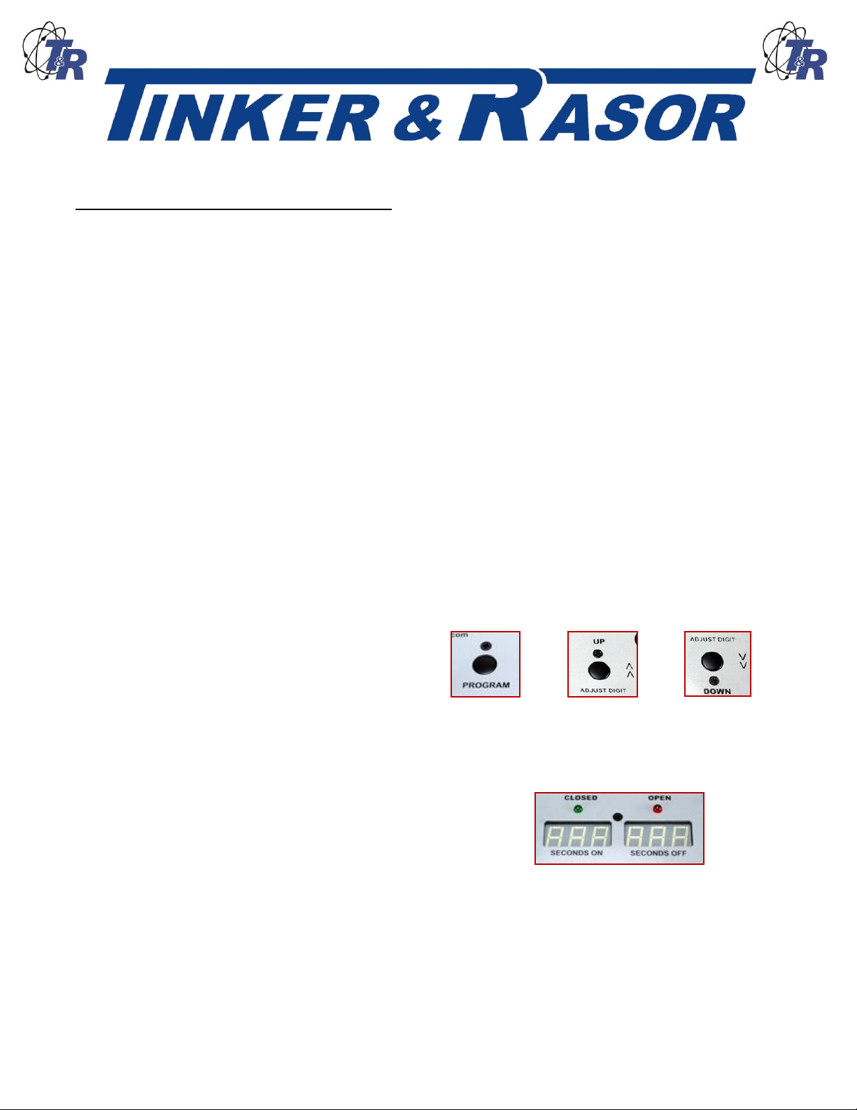
(3) Press the Program button.
(4) The first digit (Left side) begins to blink.
(5) Press the appropriate Adjust Digit button (Up or Down) to change the display to the
desired digit.
(6) When the Left most number is the correct digit for your programming, press Program
button again, and the next digit begins to blink. This digit
may now be adjusted using the Adjust Digit buttons.
(7) Repeat steps 3 through 6 until all six (6) digits have been
programmed.
(8) Press Program button again and the display will turn off.
The Model CI-50 is now programmed and ready for operation.
NOTE: When the Display is shown by pressing the View Program button, the
instrument cannot be programmed. The Program button will not work until the
Display is turned off by again pressing the View Program button, or by
automatically shutting off. Once the Display is off, the Program button can be used.
Tel: (909) 890-0700 Fax: (909) 890-0736
P. O. BOX 1667 SAN BERNARDINO, CA 92402
Web: www.tinker-rasor.com E-mail: Info@tinker-rasor.com
- 2 -
Page 3
Sponsoring members of NACE International, NACE Foundation
QMF-570 109-094
MODEL CI-50
To begin an interruption program, the Model CI-50 is first turned On by moving the Power toggle
switch to On (Up). Note the OPEN LED is lit.
NOTE: If the Low Batt LED is flashing, this is an indication that the batteries are
low. It is recommended that the batteries be changed. (See the Batteries section
below for more information.)
After initialization (display shows numbers quickly counting up, Left to Right), press the Start /
Stop button. The programmed timing sequence will begin. The On (Closed) and Off (Open)
cycles are shown by the LED indicators above each timing display.
NOTE: The LED indicators for Closed and Open stay lit for the duration of that part
of the cycle.
Connections
The Model CI-50 should always be turned Off (Power toggle switch to Off (down) when making
or breaking connections.
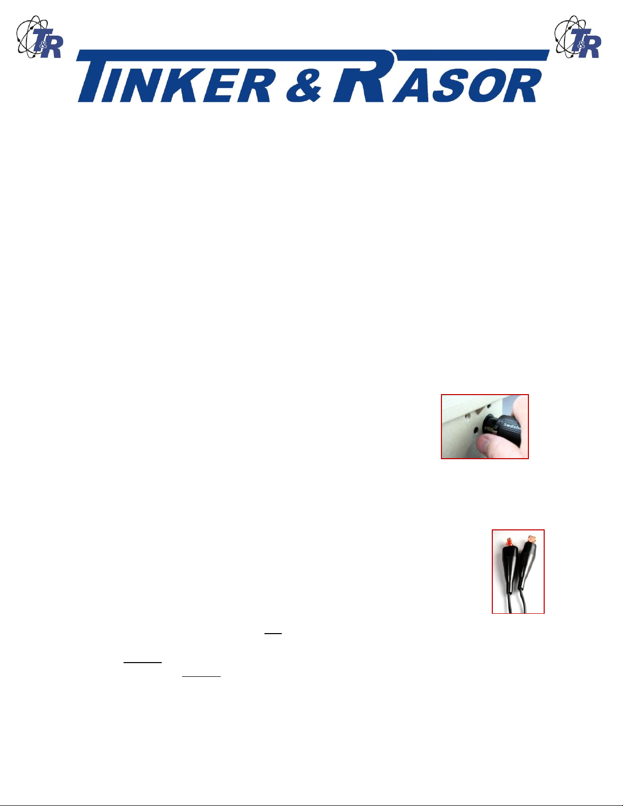
Connecting the Model CI-50 is done using the supplied cable. A single plug in –type connector
on the end of the cable is pushed into the connector on the Right side of the
case, just below the text, “MODEL CI-50” in the upper Right hand
corner of the panel.
This is a secure, locking connection. To release the plug, the release tab
must be pushed in as the cable connector is pulled away from the case. The
release tab is the silver colored tab on the cable connector. This tab should be facing the user
and easily recognized. Do not attempt to force the removal of the cable connector as this may
damage the connector(s) and render the instrument non functional.
The cable splits into two with clamps on the opposite end of the cable from the
case connector. These clamps are used to break the connection of the circuit to
be interrupted.
The clamps have a maximum jaw opening of 0.75” (19mm). Each clamp is
covered with a vinyl insulator.
The CI-50 may be connected to either the input or output side of the cathodic
protection circuit. Always be careful to observe rating limits shown in the
Specifications section, below. It is not necessary to observe polarity with output terminals.
WARNING: Do not connect the interrupter to the DC output side of rectifiers that have an
efficiency transformer. Always interrupt the AC (input) circuit.
NOTE: The CI-50 is designed to be used by trained individuals. Many jurisdictions
have laws or recommendations for the type of training necessary in order to handle
Tel: (909) 890-0700 Fax: (909) 890-0736
P. O. BOX 1667 SAN BERNARDINO, CA 92402
Web: www.tinker-rasor.com E-mail: Info@tinker-rasor.com
- 3 -
Page 4

Sponsoring members of NACE International, NACE Foundation
QMF-570 109-094
MODEL CI-50
high voltage connections. Consult your company or jurisdiction for guidance in the
type of training necessary to use this instrument properly.
Operation
Once connections are made to the circuit to be interrupted, the instrument is ready for operation.
Turn the instrument Power toggle switch to On (Up). Verify programming by the pressing View
Program button. If changed to programming are necessary, turn the Display off (if on) by again
pressing the View Program button. Press the Program button and proceed as described in the
Programming section above.
The instrument begins operation once the Start / Stop button is pressed. To end operation, press
the Start / Start button once more, or turn the Power toggle switch to Off (Down).
The Model CI-50 is a normally Open (Off) instrument. This means that when not in operation or
when the power is turned off, the circuit through the instrument is Open (Off). When a program
begins, the program always starts in the Open (Off) position.
Batteries
The Model CI-50 is battery operated. The instrument uses four (4) “AA” size alkaline batteries.
It is not recommended that rechargeable batteries be used in this instrument.
The CI-50 has a Low Battery indication. The Low Batt LED to the Right of the
Power toggle switch will begin to flash when a low battery condition is detected.
When the Low Batt LED is flashing, it is recommended that the batteries be
replaced.
Battery life for the Model CI-50 is expected to be
approximately 80 hours. Program timing and ambient
temperature will have an effect on the battery life.
When replacing the battery, observe polarity. The “AA” batteries
are placed with two (2) positive (+) up and two (2) positive (+)
down. Reversed polarity will cause the instrument to be nonfunctional. The CI-50 will not be harmed by such a connection, but it will not operate.
It is useful to carry extra batteries when working in remote field locations.
Tel: (909) 890-0700 Fax: (909) 890-0736
P. O. BOX 1667 SAN BERNARDINO, CA 92402
Web: www.tinker-rasor.com E-mail: Info@tinker-rasor.com
- 4 -
Page 5

Sponsoring members of NACE International, NACE Foundation
QMF-570 109-094
MODEL CI-50
View Programming
To conserve battery life, the Model CI-50 has an automatic shutoff of the Display.
To View the program in the instrument, press the View Program button. The
Display will come on for a few seconds, showing the programmed timing. To turn
off the Display, press the View Program button again. If the View Program button is not used to
turn off the Display, the Display will be automatically be turned off in ten (10) seconds.
NOTE: When the Display is shown by pressing the View Program button, the
instrument cannot be programmed. The Program button will not work until the
Display is turned off by again pressing the View Program button, or by
automatically shutting off. Once the Display is off, the Program button can be used.
Stopping / Ending Operation
To stop the operation of the Model CI-50, press the Start / Stop button. The
instrument can also be stopped by moving the Power toggle switch to Off (down).
Maintenance
The Current Interrupter does not require maintenance other than occasional battery
replacement. Normal care in use and storage will give many years of trouble-free service.
However, should the Current Interrupter require factory service, ship (freight prepaid) to:
Tinker & Rasor
ATTN: Repair
791 S. Waterman Ave
San Bernardino, California 92408
USA
109-094
Tel: (909) 890-0700 Fax: (909) 890-0736
P. O. BOX 1667 SAN BERNARDINO, CA 92402
Web: www.tinker-rasor.com E-mail: Info@tinker-rasor.com
- 5 -
Page 6

Sponsoring members of NACE International, NACE Foundation
QMF-570 109-094
MODEL CI-50
Maximum
Current:
50 Amps
Maximum
Voltage:
120 Volts
Maximum
Wattage:
6000 Watt
ON (Closed)
Cycles:
0.1 sec to 99.9 sec (Programmable)
OFF (Open)
Cycles:
0.1 sec to 99.9 sec (Programmable)
Battery Size:
AA size
Battery Type:
Alkaline
Battery Volts:
(4) 1.5v AA
Cable Size:
10 AWG (6.0 mm2)
Cable Type:
Stranded copper, PVC jacketed (Black)
Cable Length:
6’ (1.83m)
Cable Clamp:
(2) Copper, 75A rated, 0.75” (19 mm) Jaw Opening, 3.00” (76.2
mm) length
Case Dimension:
9.25" x 7.12" x 4.12" (23.5 x 18.1 x 10.5 cm)
Case Type:
Tough, thermo-resin plastic (Pelican® type)
Case Info:
Closing and locking lid, with carrying handle
Weight:
4 lbs (1.81kg)
Specifications of the Model CI-50
Tel: (909) 890-0700 Fax: (909) 890-0736
P. O. BOX 1667 SAN BERNARDINO, CA 92402
Web: www.tinker-rasor.com E-mail: Info@tinker-rasor.com
- 6 -
Page 7

Sponsoring members of NACE International, NACE Foundation
QMF-570 109-094
MODEL CI-50
TECHNICAL APPENDIX A
Important Note Regarding Rectifier Spikes
Most rectifiers experience a voltage spike when opening and closing, due to a capacitance effect
in the system that can be quite large and very fast. Depending upon the magnitude and duration
of the spike, the CI-50, and most other current interrupters made today, can become significantly
damaged.
It is recommended that an oscilloscope be connected to a rectifier and the rectifier be manually
cycled to see what type of spike may be present, prior to using an interrupter.
This step becomes especially important when the DC output of the rectifier is ≥ 50% or of the
maximum current the interrupter can handle. In the case of the Quasar, which is a 100 Amp max
instrument, a rectifier with an output greater than 24 amps should be investigated with an
oscilloscope.
The Magnitude and duration of the voltage spike is expressed in the graph below. The green
area of the graph is 0 – 750 volts and 0 – 2 milliseconds (0.002s) of time. The red area shows
higher voltages and longer durations which can damage the instrument.
If a rectifier is found to have a voltage spike in the red area of the graph, it is not suggested that
the current interrupter be used if the current to be interrupted is greater than or equal to 50% of
the max specified current of the instrument.
Tel: (909) 890-0700 Fax: (909) 890-0736
P. O. BOX 1667 SAN BERNARDINO, CA 92402
Web: www.tinker-rasor.com E-mail: Info@tinker-rasor.com
- 7 -
 Loading...