

Page 1
+
ASSEMBLY
MANUAL
TINKERINE STUDIO
3D Printer + Creative Solution
Page 2

CONTENTS
TINKERINE
STUDIO
STUDIO
Safety Instructions
Ditto at a Glance
Bill of Materials
Before You Start
Z-Platform
Ditto Frame pt.1
Ditto Frame pt.2
Gantry pt.1
Gantry pt.2
Gantry pt.3
Extruder
Electronics / Spool Holder
Print Bed
3
4
6
7
8
13
21
27
37
45
49
67
68
Wiring
Preliminary Run Through
71
75
[email protected] | 1-604-288-87782
Page 3

TINKERINE
STUDIO
STUDIO
IMPORTANT SAFETY INSTRUCTIONS
WARNING
!
SHARP EDGES
printer to ensure no sharp edges will cut you.
Inspect the printer for any damage prior to use.
! WARNING
HOT SURFACE
Motor surfaces become hot during operation.
Hotend and heater cartridge become hot during
operation.
DO NOT touch hot surfaces, because they can cause
severe burns.
Allow the hotend to cool before touching it without
proper tools.
! WARNING
WARNING
!
FIRE
Use caution to minimize risk of re.Use caution during assembly and operation of the 3D
Always operate the printer a safe distance away from
ammable items. Use in well-ventilated areas.
DO NOT place a storage cover on the unit during
operation. Only place a cover on the printer after it has
thoroughly cooled down.
!
WARNING
SHOCK
There is a danger of electric shock.
Use only undamaged electrical chords.
DO NOT touch bare wires or receptacles.
DO NOT touch the 3D printer or chords if hands
are wet.
Ensure that all cords are free of damage before
connecting to the power supply.
Ensure that you have a sufcient electrical supply for
supporting the requirements of the motor.
RISK TO BREATHING
Always use your 3D printer in a well-ventilated and
clean area.
Gas emitted by melting of Polylactide (PLA) or
Acrylonitrile butadiene styrene (ABS) can contain
contaminants that are harmful to breathe.
Never breathe the air that comes directly out of the
hotend. This air is not suitable for breathing.
If you feel ill from breathing while operating your 3D
printer, stop and seek medical attention immediately.
!
WARNING
Fragile
Electrical pins and sensors are delicate. Handle with
care.
Unless instructed, DO NOT force components together.
Read the instructions carefully to prevent damaing parts
during assembly or operation.
[email protected] | 1-604-288-87783
Page 4
TINKERINE
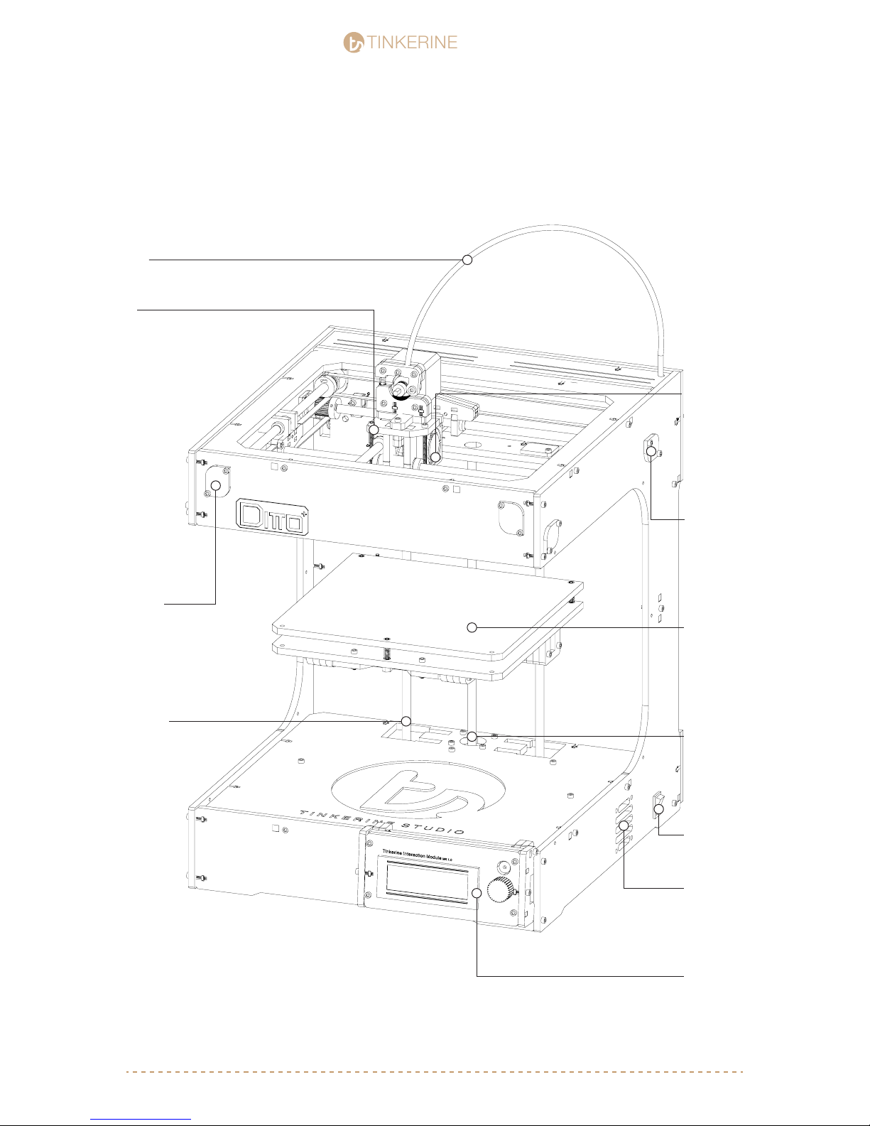
DITTO AT A GLANCE
FILAMENT
GUIDE TUBE
CARRIAGE
STUDIO
STUDIO
HOTEND
COOLING FAN
X-AXIS
BEARING CAP
Z-AXIS
SMOOTH ROD
Y-AXIS
BEARING CAP
PRINT BED
Z-AXIS
THREADED ROD
POWER
SWITCH
ELECTRONICS
FAN GRILL
TINKERINE
INTERACTION
MODULE
[email protected] | 1-604-288-87784
Page 5

TINKERINE
DITTO AT A GLANCE
EXTRUDER MOTOR
STUDIO
STUDIO
EXTRUDER
MOTOR
COMPARTMENT
SPOOL HOLDER
PRINT COOLING FAN
HOTEND
PRINT BED
Z-AXIS PLATFORM
TINKERINE
INTERACTION
MODULE
[email protected] | 1-604-288-87785
Page 6

TINKERINE
Ditto+ Bill of Material
STUDIO
STUDIO
Ditto+ Laser Cut Panels
(1) Hotend
(1) Cartridge heater
(1) Thermistor
(1) NEMA17 Extruder motor
(1) “Tensioning” bearing
(1) Cooling fan ducts
(1) Filament guiding tube
(2) 166mm GT2 belt
(2) 602mm GT2 belts
(2) 545mm GT2 belts
(8) Brass slider bushing
(8) 608ZZ ball bearings
(4) LM8 linear bearings
(8) Pulleys + (8) 3x5mm set screws
(2) 16-tooth pulleys
(8) Steel rods
(1) Bed plate
(3) Calibration springs
(3) Mechanical endstops
(3 Thumb Screw
(2) LED strips
(2) 40mm cooling fans
(1) 50mm cooling fans
(2) NEMA17 stepper motors
(1) NEMA17 stepper motor with threaded rod
(1) Arduino MEGA 2560
(1) RAMPS 1.4
(4) A4988 stepper drivers
(1) Power supply
(1) Power switch
(1) Female power plug
(1) Power cord
(1) USB cable
(30) M3 x 10 screws
(85) M3 x 16 screws
(12) M3 x 20 screws
(8) M3 x 25 screws
(11) M3 x 35 screws
(3) M3 x 50 screws
(3) M3 x 25 athead
(1) M4 x 16 screws
(3) M4 x 20 screws
(10) M3 washers
(100) M3 nuts
(1) M4 washers
(10) M4 nuts
(2) Wires (Arduino to Power)
Tool List
Included In Kit
(1) M4 Allen Key
(1) M3 Allen Key
(1) 1.5mm Hex Key
(2) Zip Ties
[email protected] | 1-604-288-87786
Page 7

TINKERINE
STUDIO
STUDIO
Before you Start
Before you attempt to assemble any of part the Ditto / Litto 3D Printer, it is imperative that you
read the build instructions fully and ensure you understand every part of the instruction.
While Tinkerine Studio provides warranty for all parts of the 3D printer, this does not cover damage
caused by not following the instruction manual or other end-user error.
Go down the BoM (Bill of Material) and tools checklist and ensure that you have all the
required parts to assemble the Ditto 3D Printer. Extra screws have been included into the kit.
If you nd anything missing, please contact us via e-mail at [email protected]
Give yourself plenty of room and clean space during the assembly process. This prevents
delicate components like the electronics or bearings from being damage by dust or blunt force.
To ensure proper alignment of the panel and overall rigidity of the printer, it is highly
recommended that the assembly is done on a at surface.
Wipe off any excess grease you nd on the screws with a napkin or an old towel. Screws
are generally greased in order to prevent rusting during production. Cleaning off excess
grease will keep your hands and printer clean during assembly.
Ditto is a rigid and robust 3D printer once assembled, however during the assembly process,
extra care needs to be taken to make sure delicate parts require more precision than force to
come together. If during the assembly process, you are unsure of the instructions, please
contact us for support. Remember, unless instructed, no part in the assembly process should
you need to exert a high amount of force to t pieces together.
Before starting calibration, ensure that all screws and pulley setscrews are properly tightened.
Common calibration issues such as skipping and backlash are usually caused by loose pulleys
and unsecured components.
[email protected] | 1-604-288-87787
Page 8
TINKERINE
Z - Platform Assembly
STUDIO
STUDIO
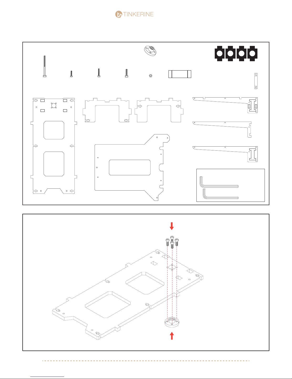
Parts Required
M3x35 Screw
x10
Z-Base
M3x10 Screwx4M3x16 Screwx4M4x20 Screw
x1
Z-Bridge
Bed Plate
Lead Screw Nut
x1
M3 Nuts
x14
(Attached to Z-Axis Motor)
UNSCREW TO DETACH
45mm Bearing
x2
Tools Required
Bearing Holder
x4
x2
x4
x2
1.
M4 Allen Key
M3 Allen Key
M3x10 (x4)
Screw nut comes attached to the
lead screw motor. Remove from
screw and insert it into the
[email protected] | 1-604-288-87788
Page 9
TINKERINE
2.
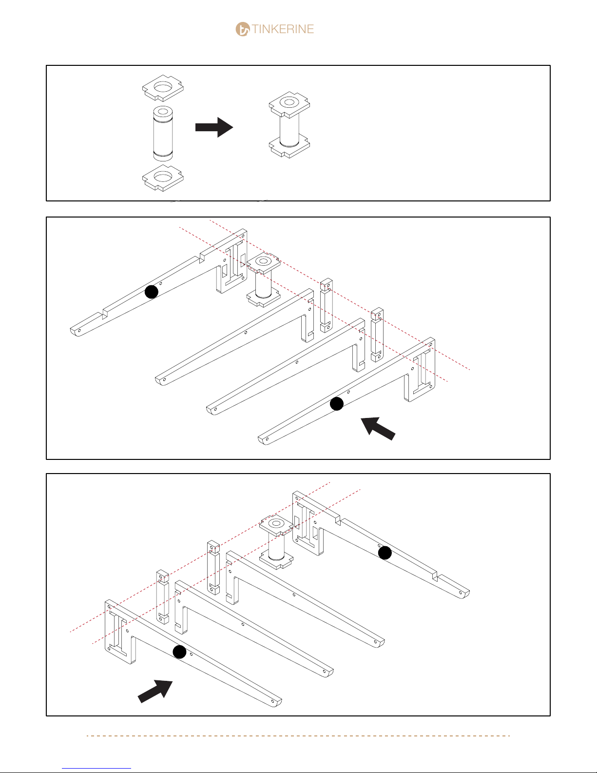
45mm Linear Bearing
STUDIO
STUDIO
Take a 45mm linear bearing and place a
bearing holder on both ends. You will need
two sets.
x2
3.
4.
Add the side arm panels to the existing
assembly, note the different panels + orientation of the arms (A + B) shown in the picture.
A
B
Arm A
Arm B
B
A
Swapping the position of the A+B pieces will
allow us to create the mirrored version of
Arm A
[email protected] | 1-604-288-87789
Page 10
TINKERINE
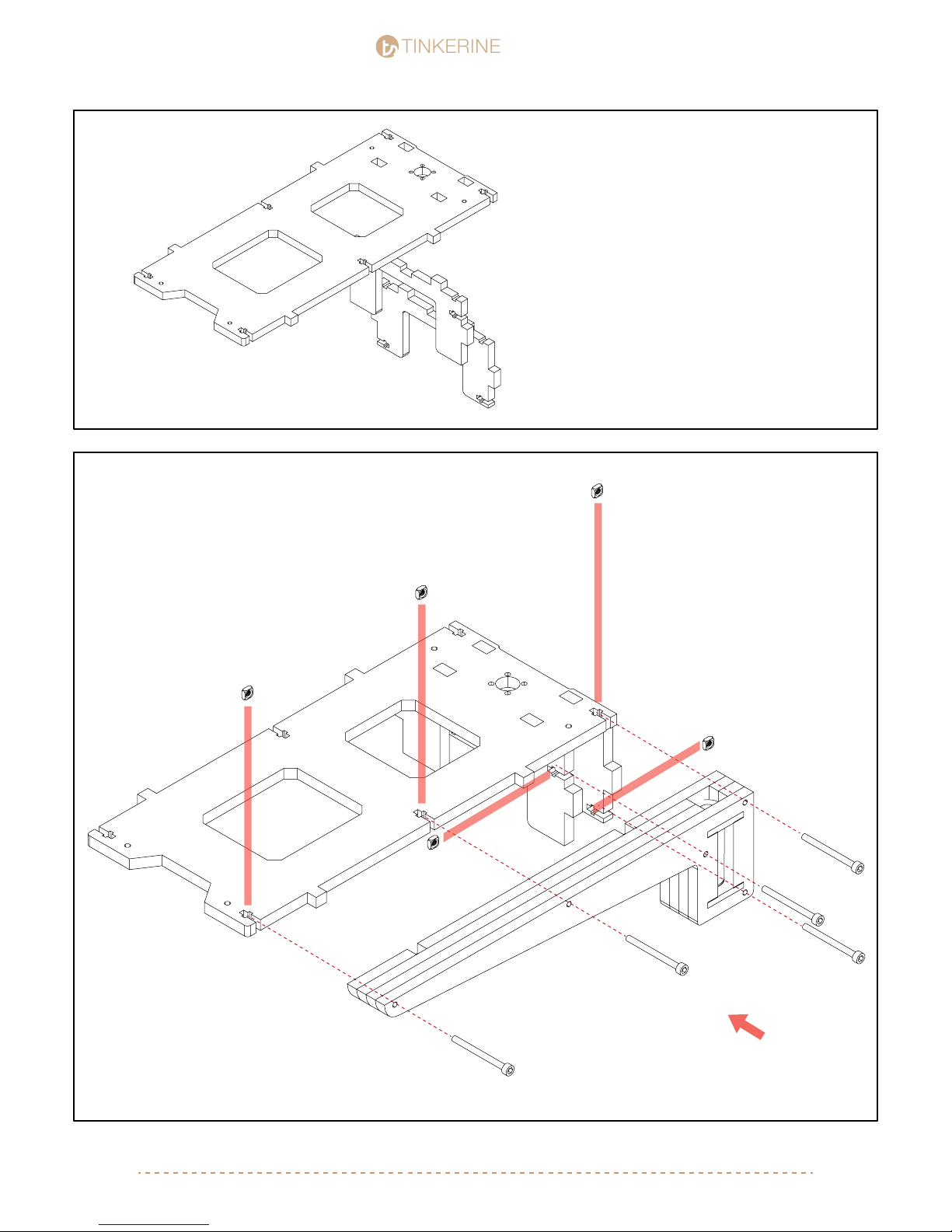
5.
One by one, insert the M3 Nut into the
6.
T-slots shown in the picture. Screw the four
M3x35 screws in but do not tighten them all
the way.
STUDIO
STUDIO
After Steps 3 and 4, you should
have two sets of the Z-axis arm
that have the outer panel that
mirror each other.
M3 Nut (x5)
M3x35 (x5)
Arm A
[email protected] | 1-604-288-877810
Page 11
TINKERINE
STUDIO
STUDIO
[email protected] | 1-604-288-877811
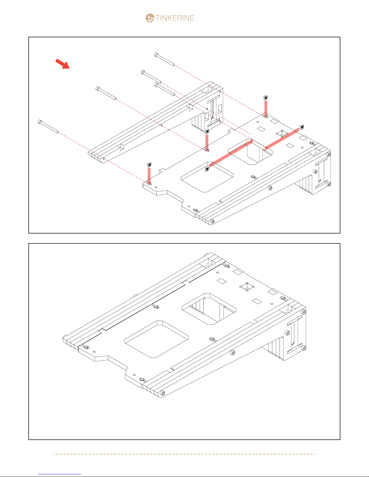
7.
8.
Arm B
Arm A
M3x35 (x5)
M3 Nut (x5)
During this point, double check to make sure
all panels are properly aligned and the top
side of the bed is leveled with the arms.
Tighten all screws evenly.
Page 12

Page 13
TINKERINE
Ditto Frame Assembly pt.1
STUDIO
STUDIO
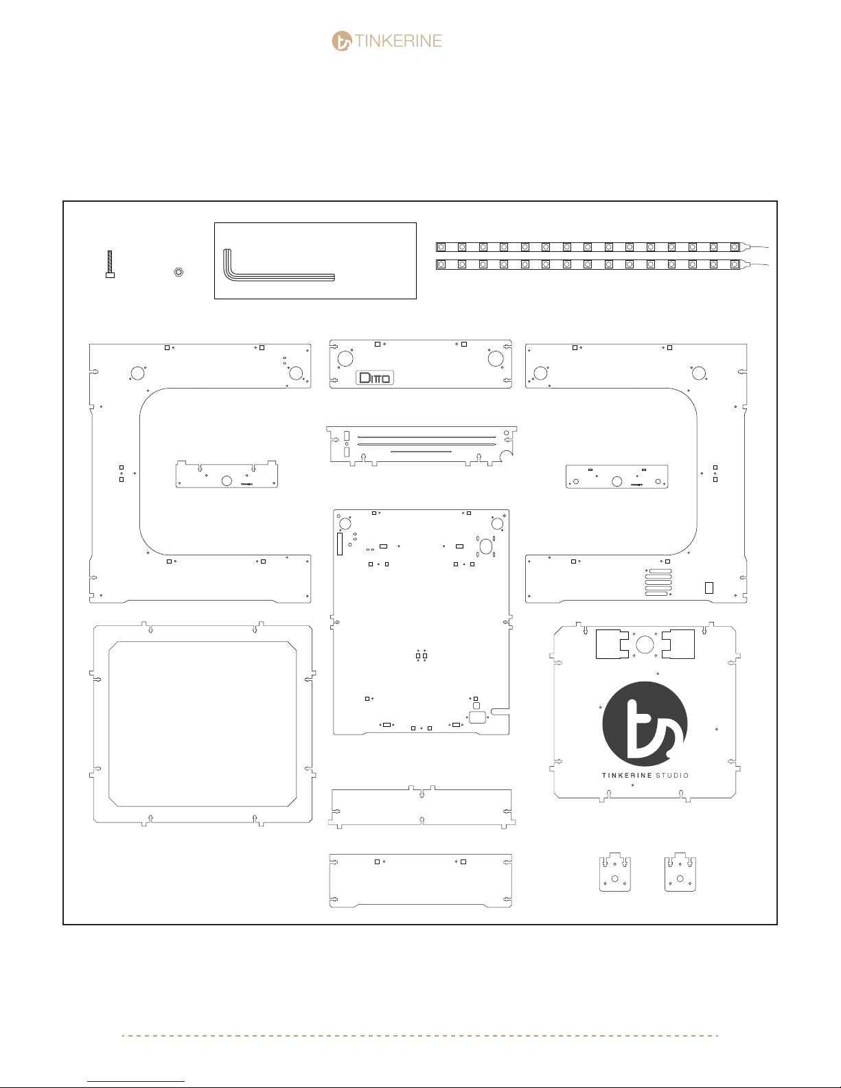
Parts Required
M3x16 Screw
x39
M3 Nuts
x39
Right Side Panel
Tools Required
M3 Allen Key
Top Front Panel
+
Motor Bracket
Central Back Panel
Adhesive LED Strips
Left Side Panel
Z-Constraint BZ-Constraint A
Base Panel
Top Ring Panel
Bottom Bracket
Bottom Front Panel
[email protected] | 1-604-288-877813
Z-Constraint C
Page 14
TINKERINE
STUDIO
STUDIO
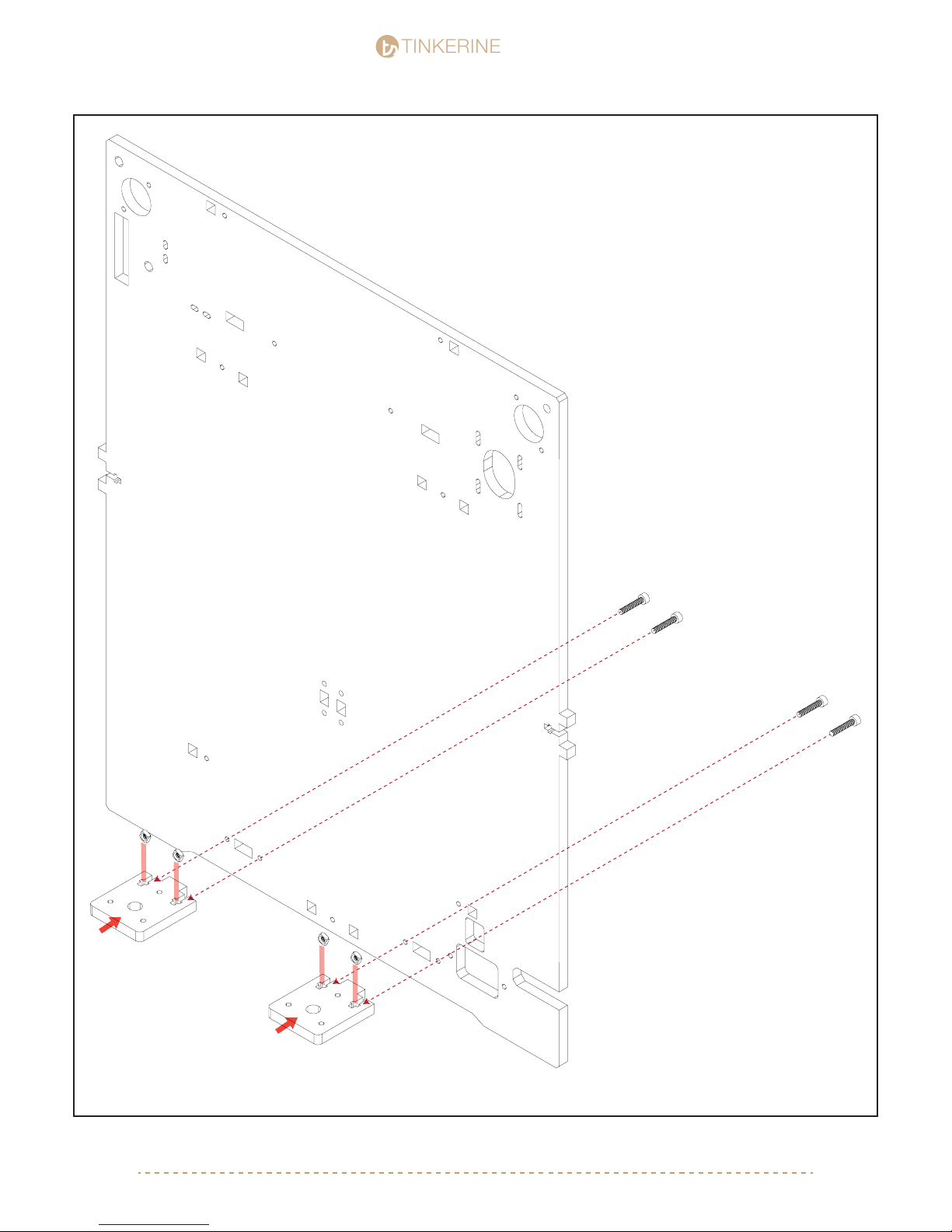
1.
Install the two Z-Constraints C as shown
in the picture. Make sure to face the back
panel in the correct direction. Insert the
constraint into the corrent tabs, place the
M3 nuts in position and screw in the
M3x16 screws from the other side.
Z-Constraint C
M3x16 (x4)
M3 Nut (x4)
[email protected] | 1-604-288-877814
Page 15

TINKERINE
2.
STUDIO
STUDIO
M3x16 (x2)
M3 Nut (x2)
B
M3x10 (x4)
A
Install Constraint A to the back panel and lightly secure with the two M3x16 screw +
nut. Insert Constraint B underneath Constraint A and secure with four M3x10 screws.
Tighten all screws once everything is aligned and in place.
[email protected] | 1-604-288-877815
Page 16
TINKERINE
Top Ring Panel
STUDIO
STUDIO
LED Strip (x2)
BACK
FRONT
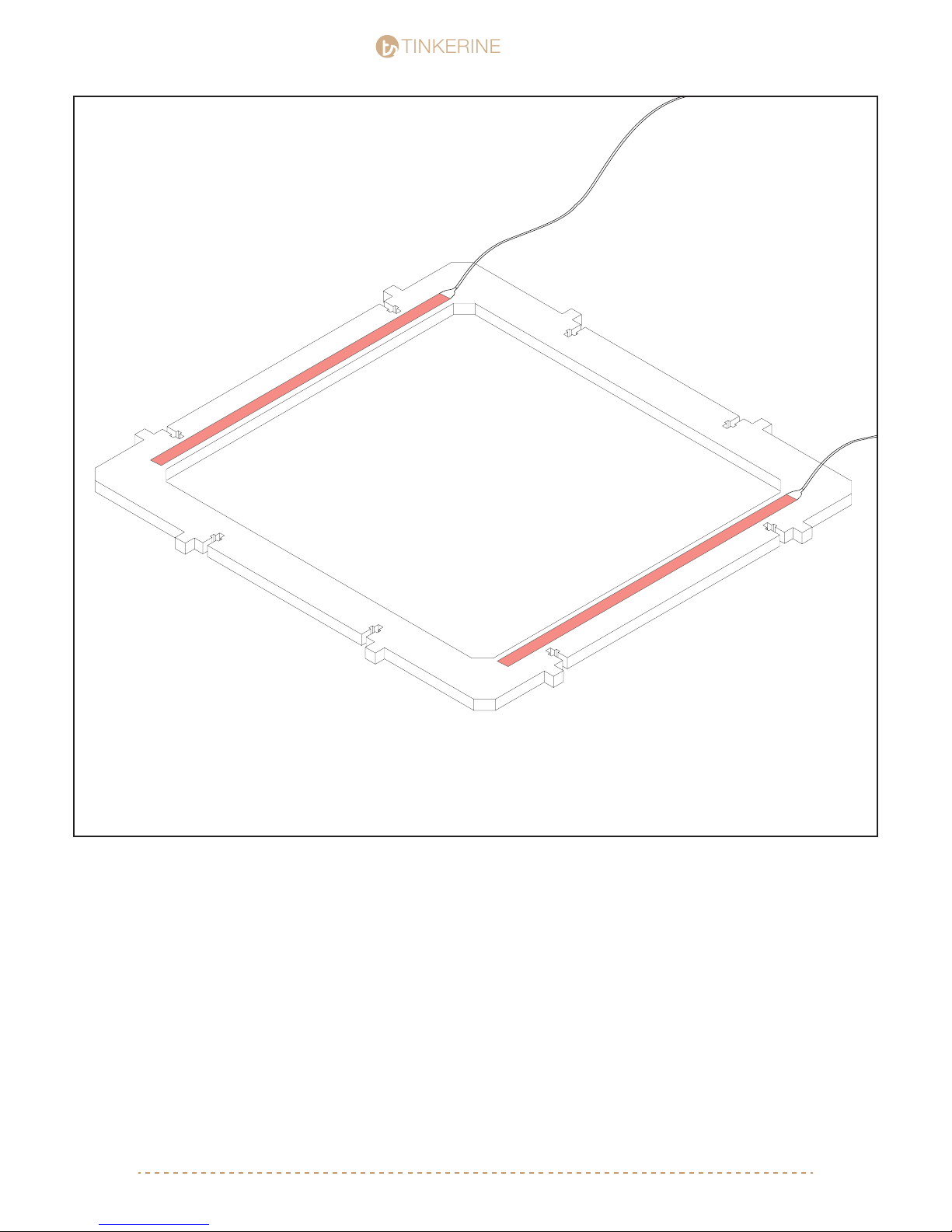
Using the two LED light strip supplied in your kit, one-by-one peel off the backing to reveal the adhesive strip
and stick the LED strip in the area shown in the picture. Make sure the LED is applied inbetween the T-Slot
and edge of the inner ring. The front and back side of the ring panel will be wider.
[email protected] | 1-604-288-877816
Page 17
TINKERINE
3.
STUDIO
STUDIO
LED Side Facing Down
M3x16 (x4)
M3 Nut (x4)
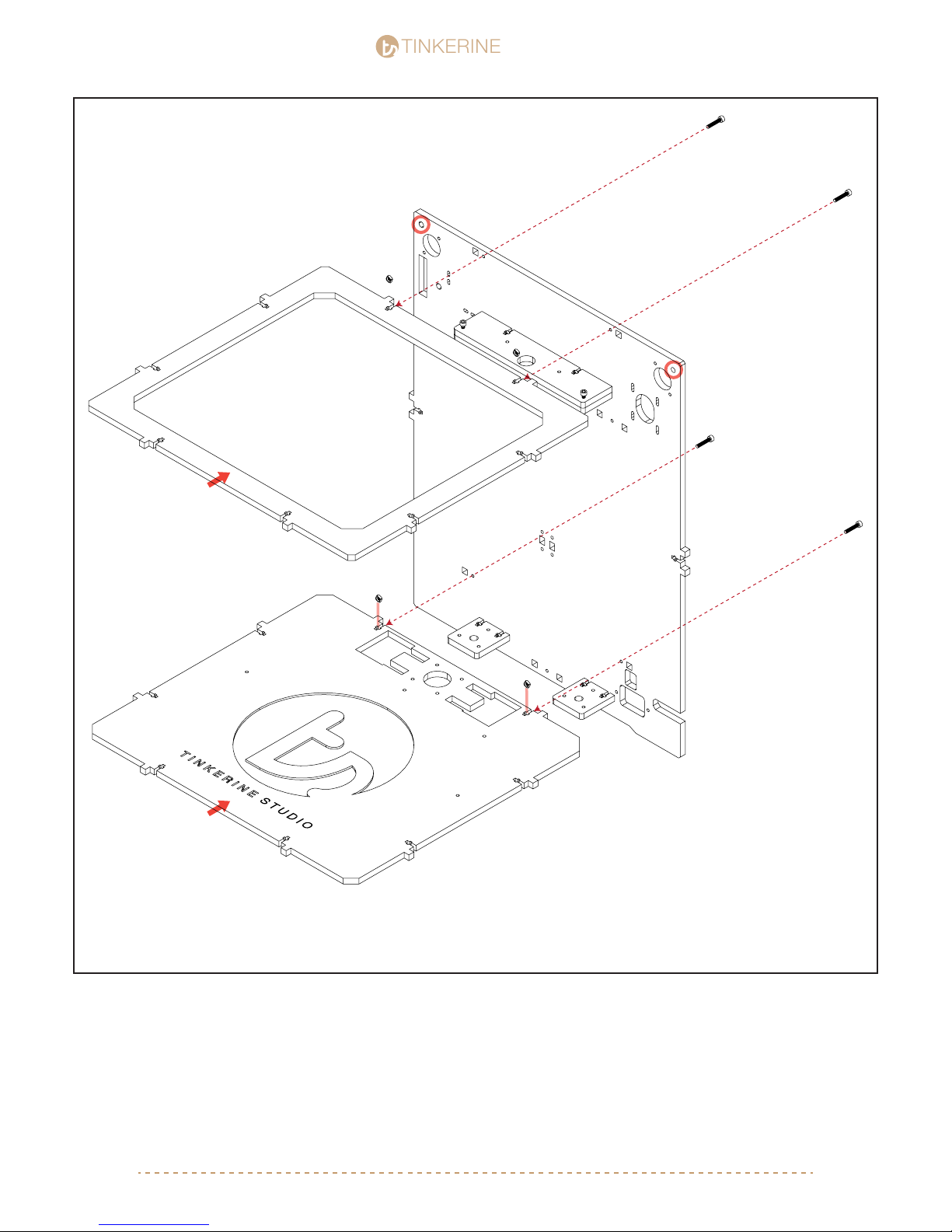
Insert the top ring and and bottom plate into the back plate, then secure with M3x16 and nuts in the T-Slots.
For the top ring, the side with the led should be facing downward. Thread the LED wires into the hole shown
in the picture.
[email protected] | 1-604-288-877817
Page 18
TINKERINE
4.
STUDIO
STUDIO
M3x16 (x10)
M3 Nut (x10)
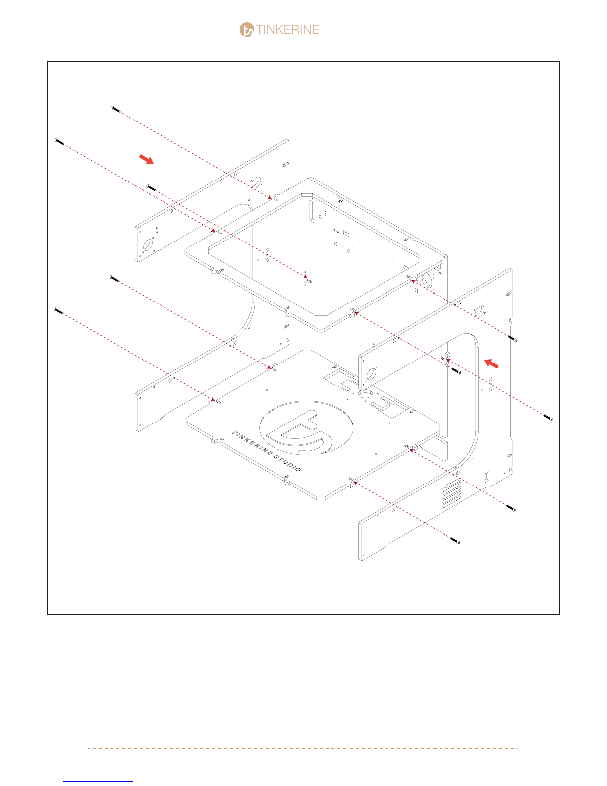
Install the two side panels into the main body. Secure each side with ve M3x16 screws and nut. Make sure
the panel with the power switch and fan grill cutout is on the right side.
[email protected] | 1-604-288-877818
Page 19
TINKERINE
5.
STUDIO
STUDIO
M3x16 (x12)
M3 Nut (x12)
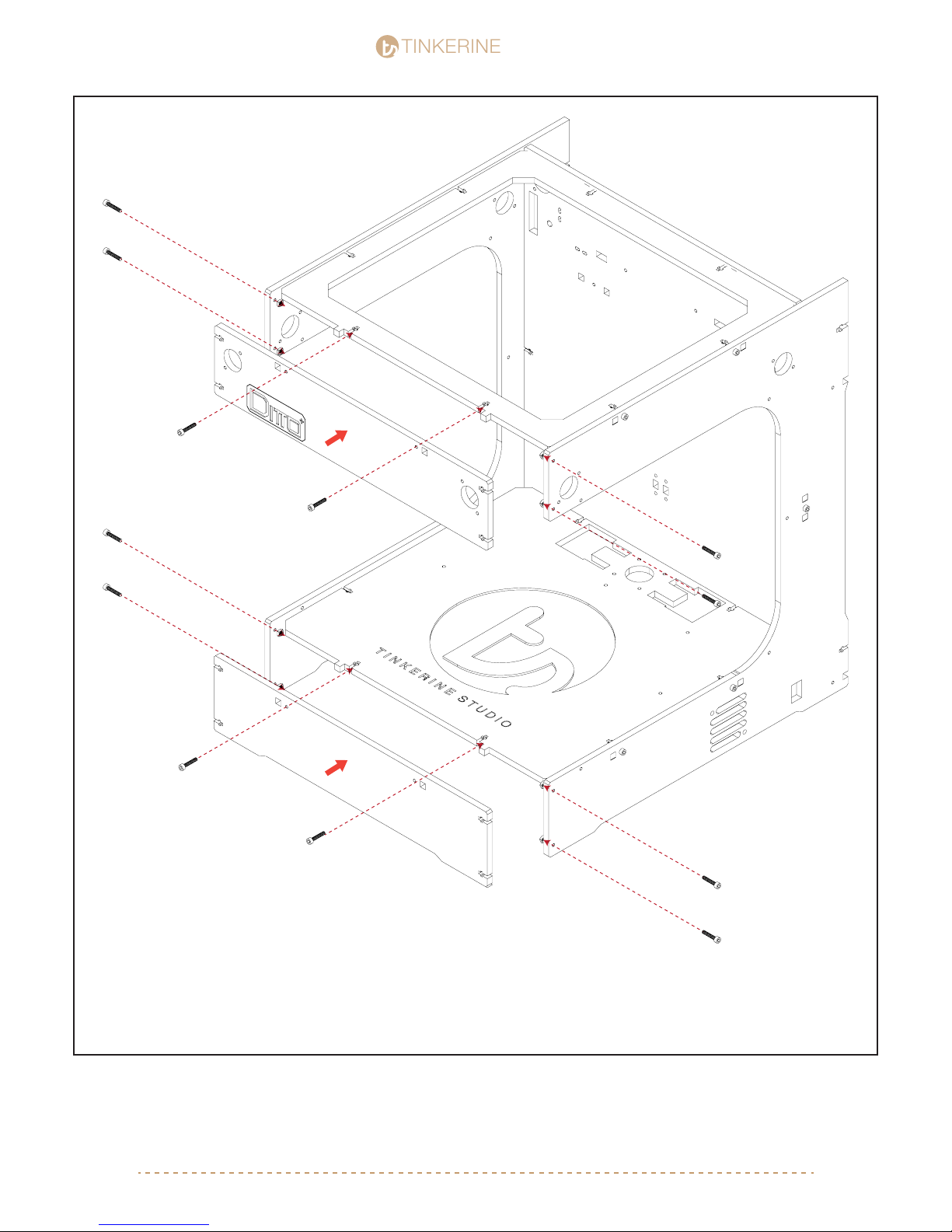
Install the top front and top bottom panels. At this point, you will want to make sure all the panels are properly
aligned and leveled to a at surface. Due to the natural property of wood you wooden frame may not be perfectly
tapered to the surface, however we can correct this later on once the other components are installed.
[email protected] | 1-604-288-877819
Page 20
TINKERINE
6.
STUDIO
STUDIO
M3x16 (x7)
M3 Nut (x7)
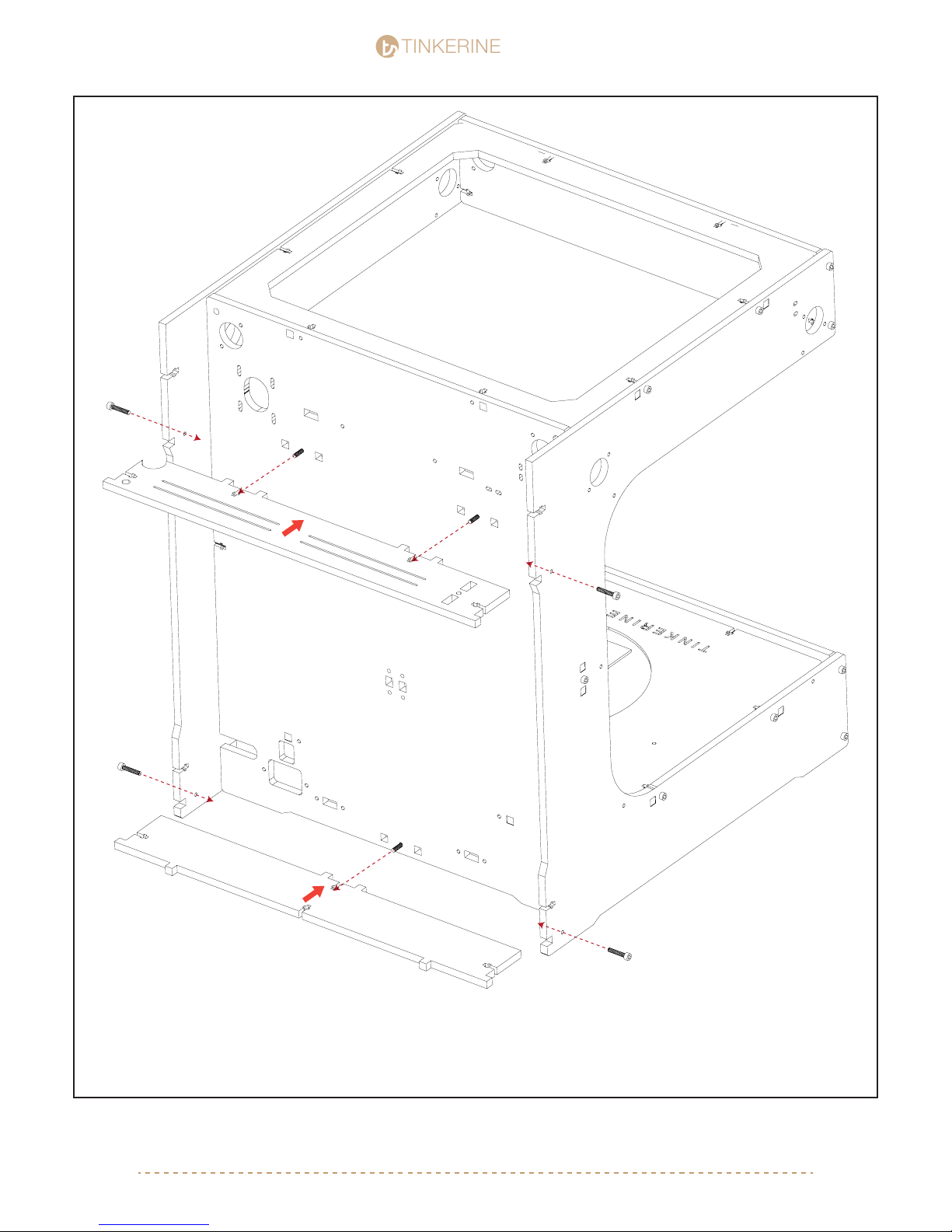
Install the top and bottom brackets into the main body. You will need to insert some screws from the front of the
machine.
[email protected] | 1-604-288-877820
Page 21
TINKERINE
Ditto Frame Assembly pt.2
Parts Required
STUDIO
STUDIO
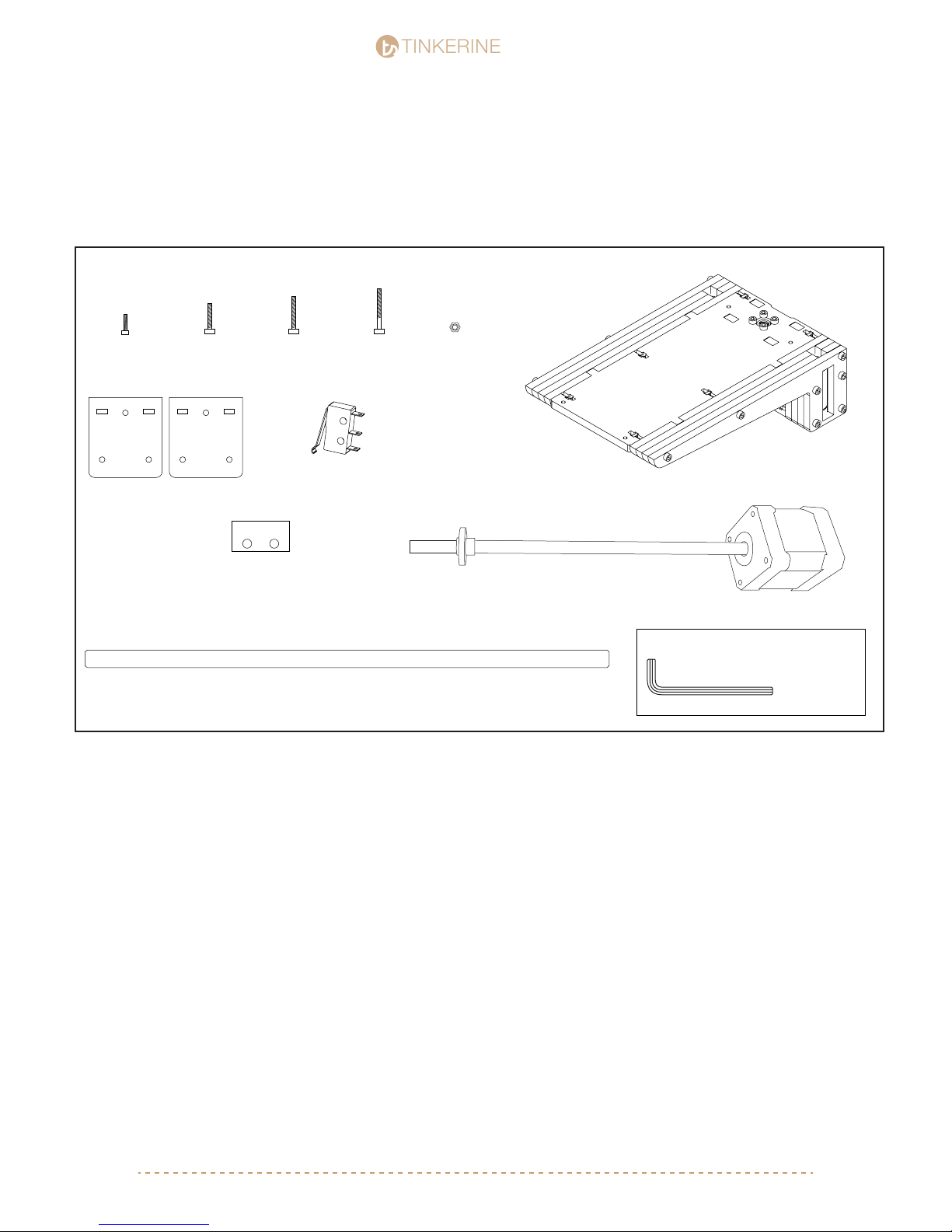
M3x10 Screw
x4
Z-Constraint D
M3x16 Screwx6M3x20 Screwx4M3x25 Screw
x2
Endstop Switch
x3
Endstop Spacer
x5
Z-Axis Smooth Rod (350mm)
x2
M3 Nuts
x12
Assembled Z-Platform
Lead Screw NEMA17 Stepper Motor
Tools Required
M3 Allen Key
[email protected] | 1-604-288-877821
Page 22
1.
TINKERINE
!
STUDIO
STUDIO
!
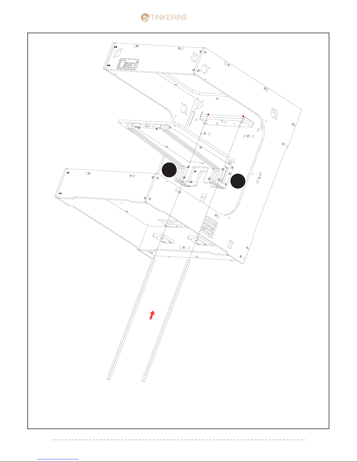
Gently insert the Z-Axis smooth rods through the bottom Z-Constraint, linear bearing of the Z-Axis bed and
nally the top Z-Constraint. If you feel there is any amount of resistance once you reach the linear bearings within
the z-axis arms, do not force it in. Pull the rod backwards gently and retry. Rotating the rod gently while inserting
may help it slide in more easily. Take your time with the bearing, forcing the rod in will cause the bearing balls to
dislodge.
Z-Axis Rods (350mm x2)
[email protected] | 1-604-288-877822
Page 23
TINKERINE
2.
STUDIO
STUDIO
The Z-Axis rods should now sit ush within the bottom and top Z-Constraint. Attach Z-Constraint D to C, secure
the two pieces together with three M3x16 screws each.
M3x16 (x6)
M3 Nut (x6)
[email protected] | 1-604-288-877823
Page 24
TINKERINE
STUDIO
STUDIO
[email protected] | 1-604-288-877824
3.
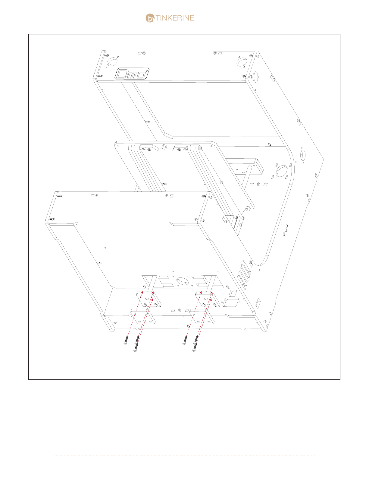
M3x10 (x4)
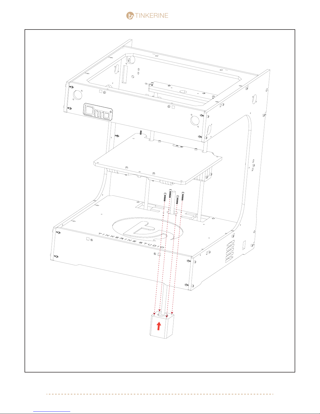
Lay the printer on its back. Insert the Z-Axis Motor and lead screw from the bottom and into the Z-Axis platform.
To connect the the lead screw into the nut within the platform you will need to manually turn the lead screw rod
until it threads into the nut. Secure the motor to the frame with four M3x10 screws.
Page 25
TINKERINE
4.
STUDIO
STUDIO
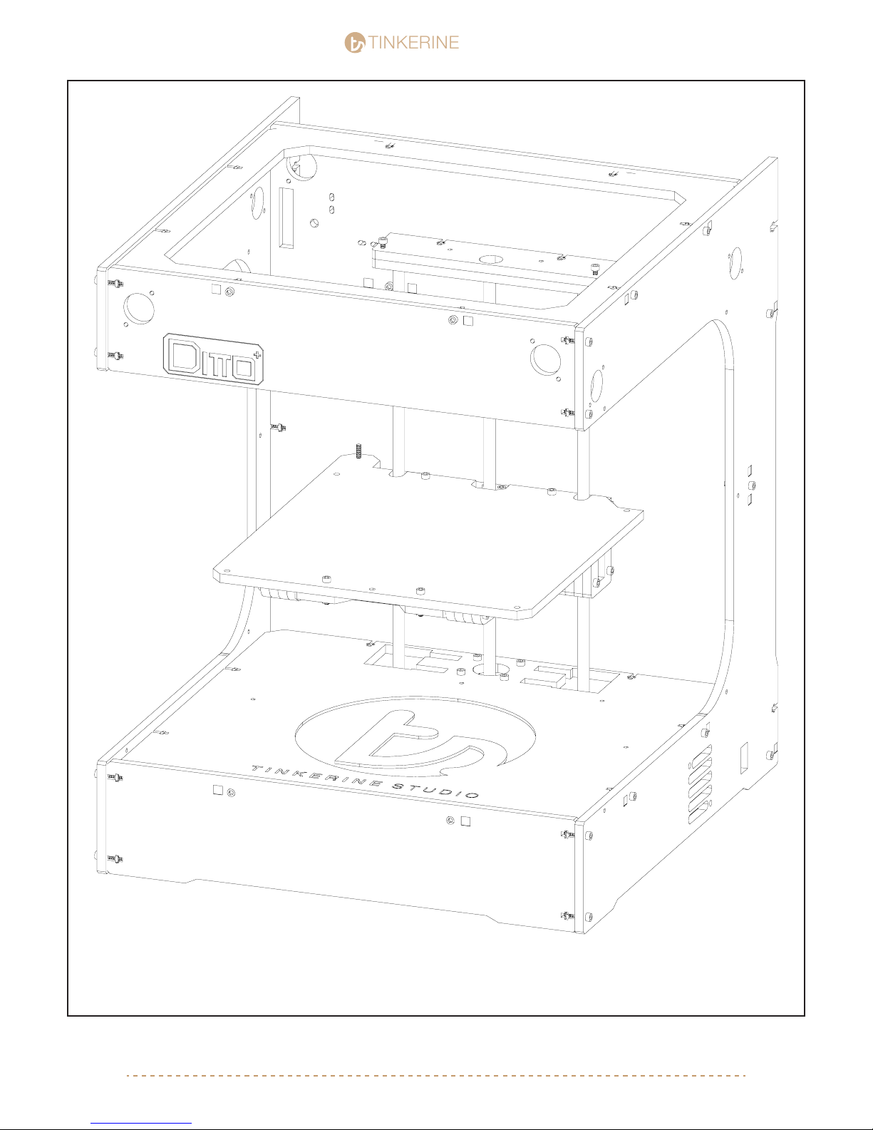
At this point, the printer’s top and bottom Z-Constraint should be in place and secured. The bed assembly is
installed and threaded onto the Z-Axis motor and the motor is secured to the bottom panel. Double check to
ensure that all screws are tightened. You may wish to manually adjust the bed by turning the lead screw to get
better access to parts of the printer.
[email protected] | 1-604-288-877825
Page 26
1.
TINKERINE
STUDIO
STUDIO
M3x20 (x2)
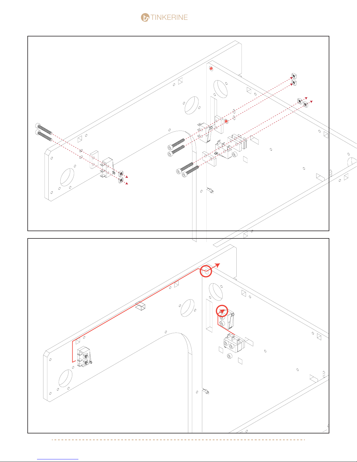
Install each endstop triggers as shown. Note the orientation of
the trigger and the direction it’s pointing. Depending on the
trigger, you will need to different amounts of spacers between
the endstop.
After the endstop trigger is installed. Thread the wires
through the holes shown in the picture. Use one of the
smaller adhesive wooden clips provided in your kit to
prevent the wire from slacking/getting caught once the
printer is in motion. Insert the wire into the clip and tape it
to the bottom side of the top ring beside the LED strip.
M3x20 (x2)
M3x25 (x2)
[email protected] | 1-604-288-877826
Page 27
TINKERINE
Gantry Assembly pt.1
STUDIO
STUDIO
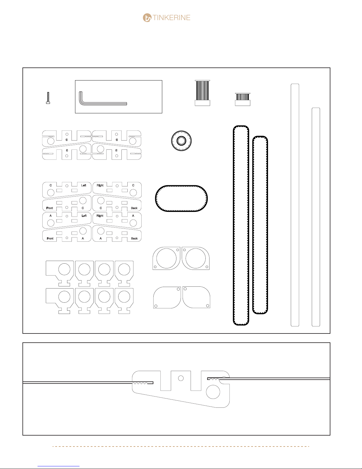
Parts Required
M3x16 Screw
x20
Tools Required
Slider Core
Slider Side Panels
M3 Allen Key
Pulley (Large)
x2
Bearing
x8
GT2 Loop Belt (166mm)
x2
Pulley (Small)
x6
GT2 Belt (602mm)
GT2 Belt (545mm)
Inner Bearing Cap
8 Pieces
Outer Bearing Cap
Bushing Holder w/ Brass Bushing
8 Pieces
8 Pieces
X-Axis Smooth Rod 350mm) x2
Y-Axis Smooth Rod (314mm) x2
1.
B
Insert both ends of the belt onto the Slider B piece. Make sure to line up the belt with the teeth so that there is no
spaces left at the end of the slots.
[email protected] | 1-604-288-877827
Page 28
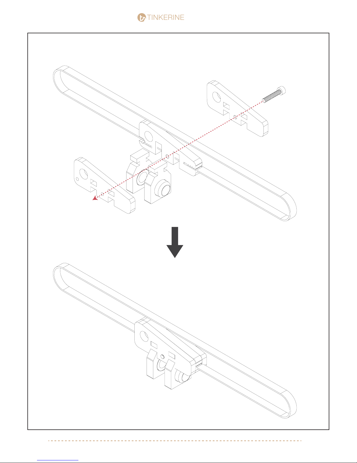
TINKERINE
2. Front Slider
STUDIO
STUDIO
M3x16
X Axis Belt - 603 mm
C
B
A
[email protected] | 1-604-288-877828
Page 29
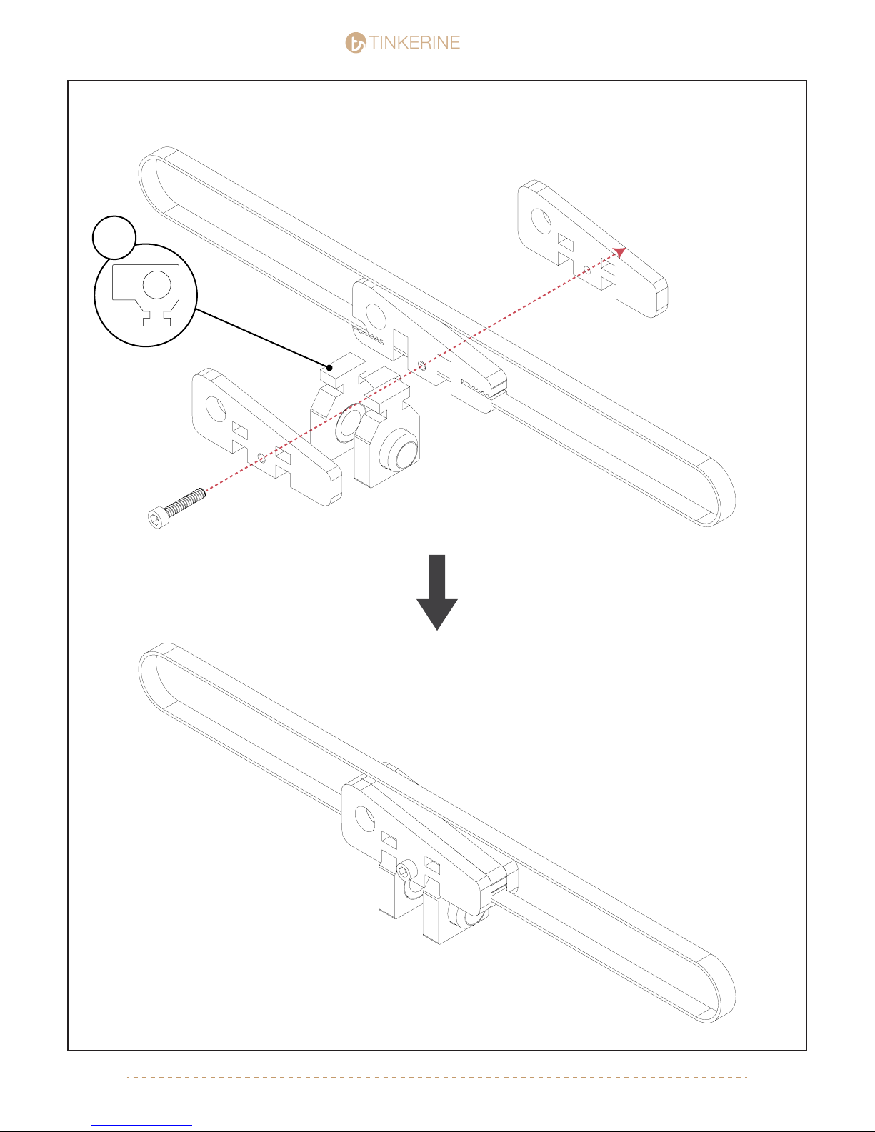
TINKERINE
3. Back Slider
STUDIO
STUDIO
!
M3x16
A
B
X Axis Belt - 603 mm
C
[email protected] | 1-604-288-877829
Page 30
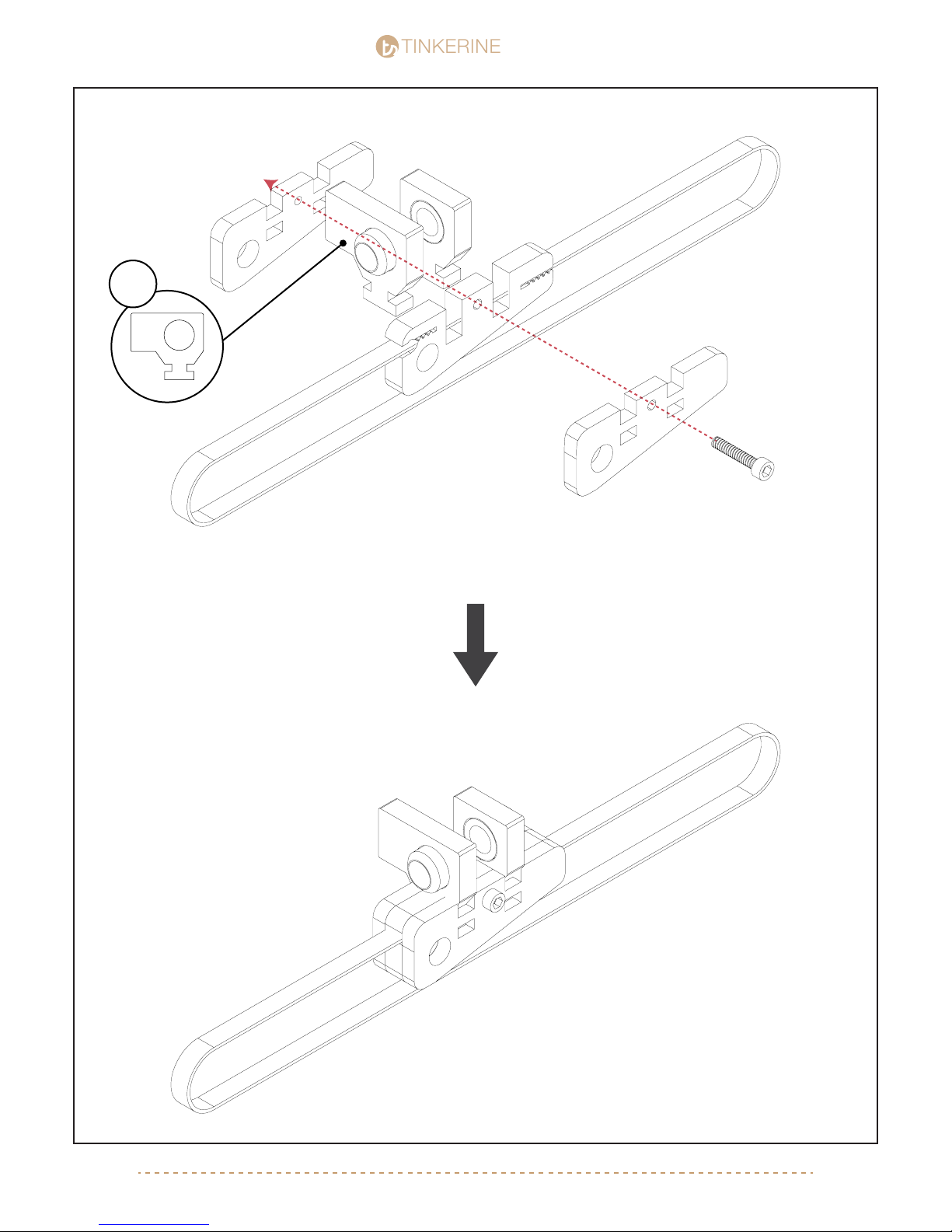
TINKERINE
!
STUDIO
STUDIO
Left Slider4.
A
Y Axis Belt - 545 mm
B
C
M3x16
[email protected] | 1-604-288-877830
Page 31

TINKERINE
Right Slider5.
M3x16
C
STUDIO
STUDIO
B
Y Axis Belt - 545 mm
A
[email protected] | 1-604-288-877831
Page 32
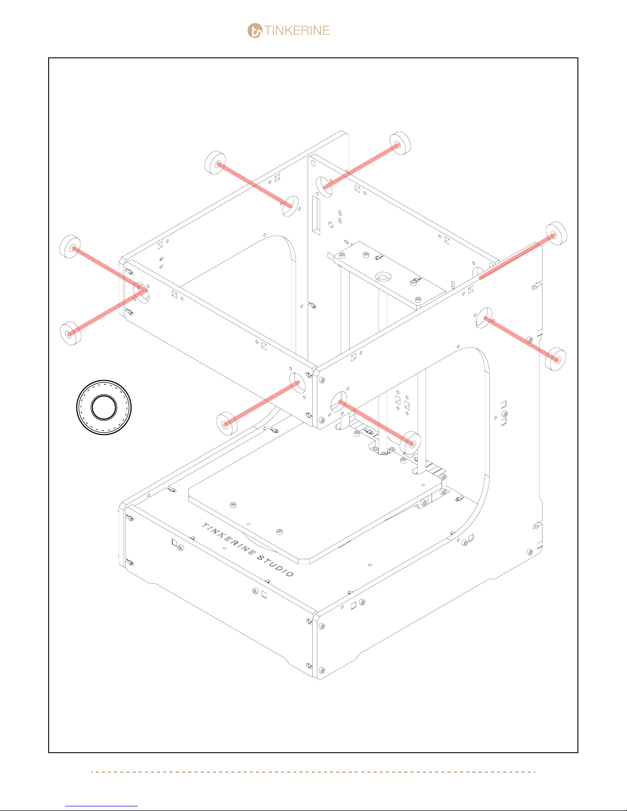
TINKERINE
6.
STUDIO
STUDIO
x8
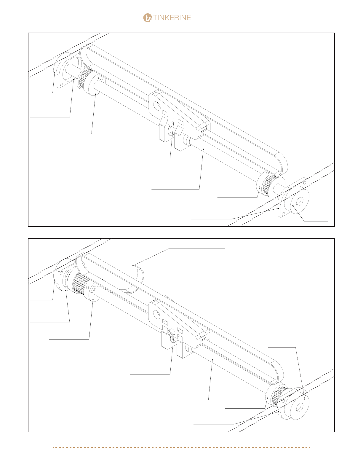
Insert eight bearing into the respective slots within the frame. The cutouts are meant to be a snug t with the
bearings, however if you have trouble putting the bearings in there, give the wooden inner ring a very light sand
with some sand paper.
[email protected] | 1-604-288-877832
Page 33
TINKERINE
Bearing
Inner Bearing Cap
Small Pulley
Front Slider
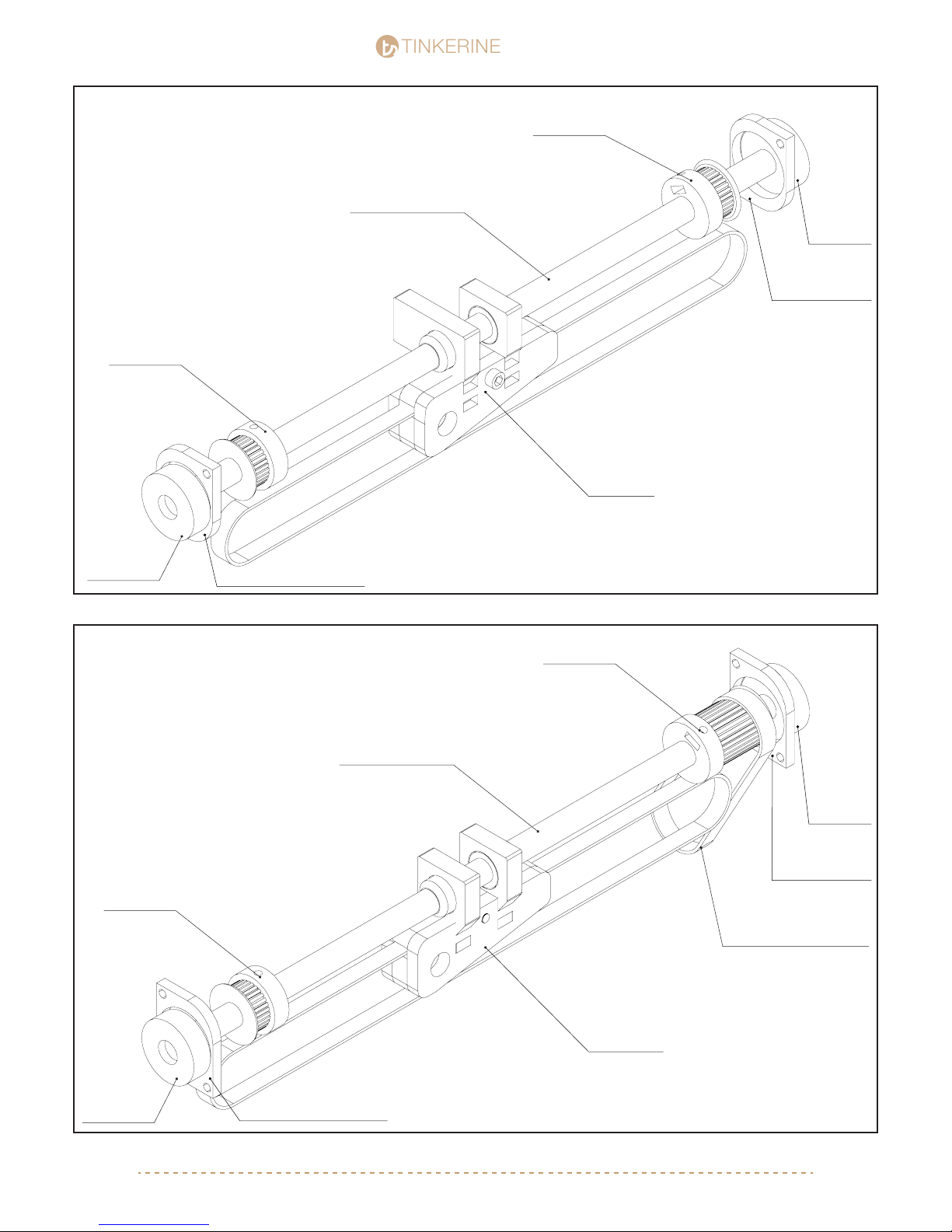
With the previously assembly slider unit, you will now need
to add the rod, pulleys, inner bearing cap, and depending
on the slider you may need to include a looped belt.
Assemble the slider units as shown on the picture and
note the orientation of the pulley and panel direction of the
inner bearing cap.
Assembled each and set aside until you have all four slider
units ready for the next step.
X-Axis Rod (340mm)
STUDIO
STUDIO
Small Pulley
7.
Front Rod
Bearing
Inner Bearing Cap
Large Pulley
Back Slider
Inner Bearing Cap
GT2 Looped Belt (166mm)
Bearing
Bearing
8.
Back Rod
X-Axis Rod (340mm)
Small Pulley
Inner Bearing Cap
[email protected] | 1-604-288-877833
Page 34
TINKERINE
Left Rod
9.
Small Pulley
Y-Axis Rod (314mm)
STUDIO
STUDIO
Small Pulley
Bearing
Inner Bearing Cap
Left Slider
Bearing
10.
Right Rod
Small Pulley
Inner Bearing Cap
Large Pulley
Y-Axis Rod (314mm)
Bearing
Inner Bearing Cap
GT2 Looped Belt (166mm)
Bearing
Inner Bearing Cap
Right Slider
[email protected] | 1-604-288-877834
Page 35
TINKERINE
11. Font + Back Slider
STUDIO
STUDIO
X-Axis Rod (350mm)
* Front panel has been hidden to show gantry*
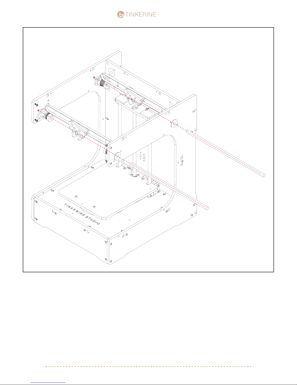
Using the previous slider assembly pictures as a reference. Insert the Front and Back slider assembly into the frame.
One way to do this would be to skewer the items on one by one as you insert the rods from one end.
For example, to insert the back rod from the right side of the frame, the order would be:
Right Inner Bearing Cap > Small Pulley > Back Slider > Large Pulley > Looped Belt > Left Inner Bearing Cap
To insert the front rod from the right side of the frame, the order would be:
Right Inner Bearing Cap > Small Pulley > Back Slider > Small Pulley > Left Inner Bearing Cap
Make sure to note the orientations of the inner bearing caps, and directions of the pulleys.
[email protected] | 1-604-288-877835
Page 36
TINKERINE
12. Left + Right Slider
STUDIO
STUDIO
Y-Axis Rod (314mm)
* Side panel has been hidden to show gantry*
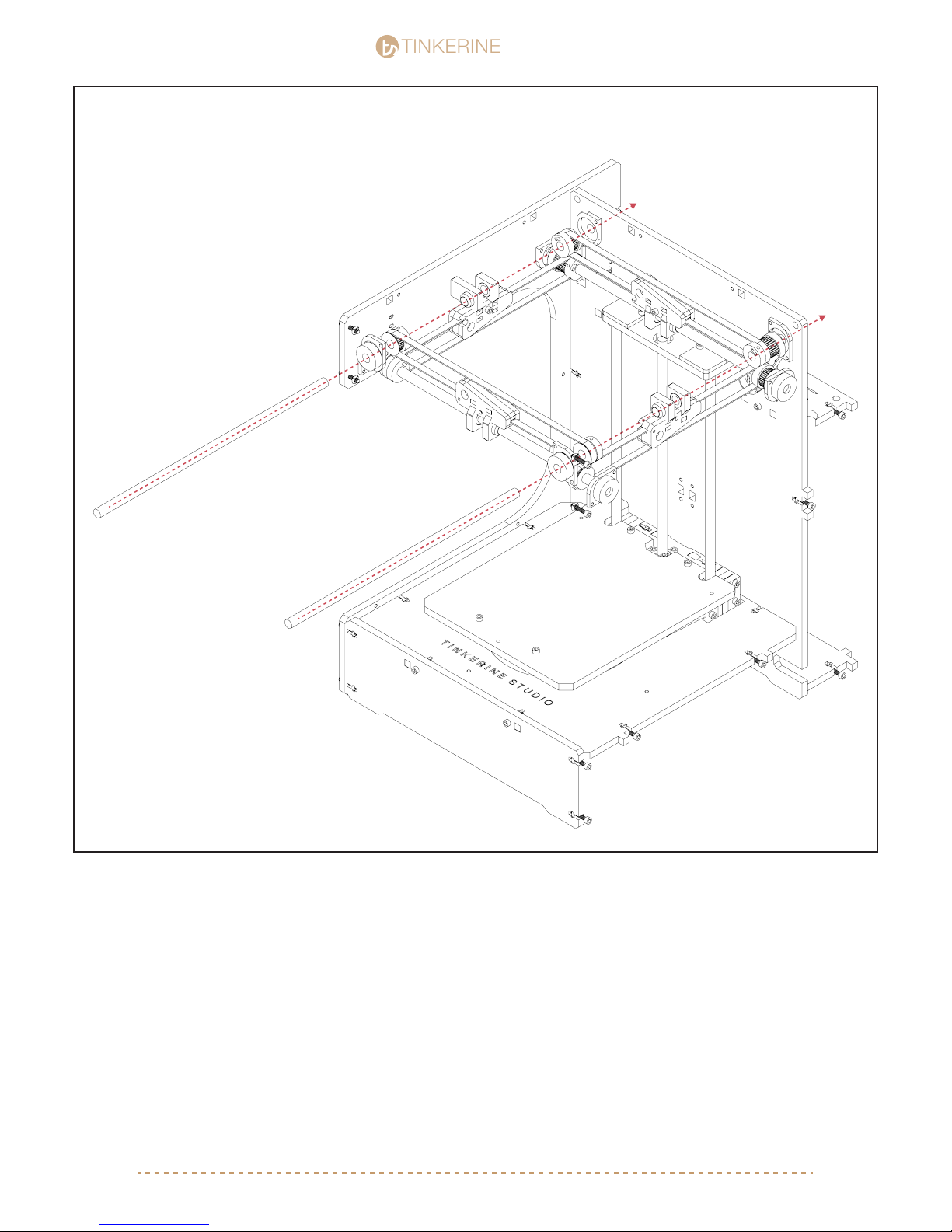
Similar to the Front and Back rod assembly, installing the Left and Rod right will require you to insert the rod from
one end while inserting the parts in order. Here is the tricky part: While skewering the pulleys onto the left and right
rods, you will also need to skewer the belts from the front and back sliders.
To insert the left rod from the front side of the frame, the order would be:
Front Inner Bearing Cap > Small Pulley > Back Slider > Small Pulley > Back Inner Bearing Cap
To insert the right rod from the front side of the frame, the order would be:
Front Inner Bearing Cap > Small Pulley > Back Slider > Large Pulley > Looped Belt > Back Inner Bearing Cap
Once the Left and Right rods are installed, you will need to pop the Front and Back rods back out slightly to loop
the belts onto the pulleys. Once the belts are seated onto the pulley, you will need to use a bit of force to insert the
rods into the bearing.
After installed the the gantry, all the belts (except for the closed loop belts) should be looping across a pulley on
each end.
[email protected] | 1-604-288-877836
Page 37
TINKERINE
13.
STUDIO
STUDIO
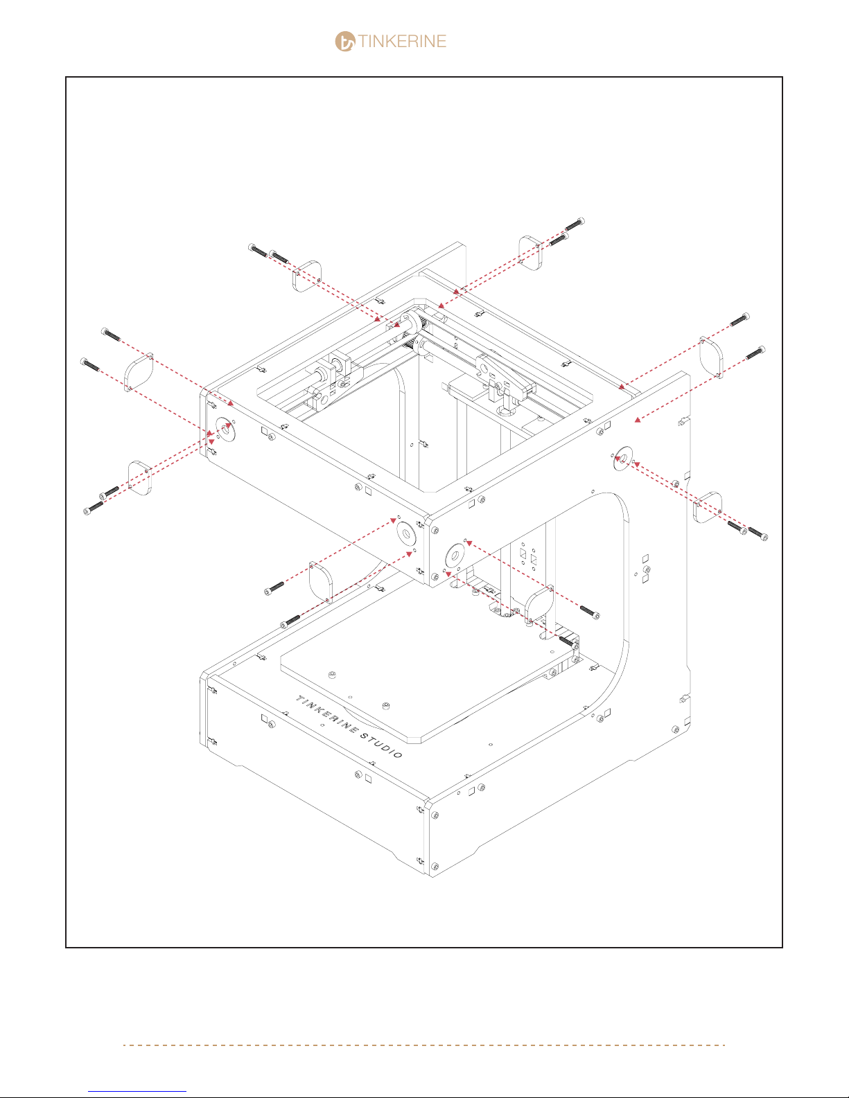
M3x16 (x16)
Install the outer bearing caps to cover the exposed bearing and prevent the rods from sliding out. If you have
oriented the inner bearing caps correctly in the previous steps, it will align with the outer bearing caps. If not,
you need need to ip the inner bearing cap.
[email protected] | 1-604-288-877837
Page 38
TINKERINE
Gantry Assembly pt.2
STUDIO
STUDIO
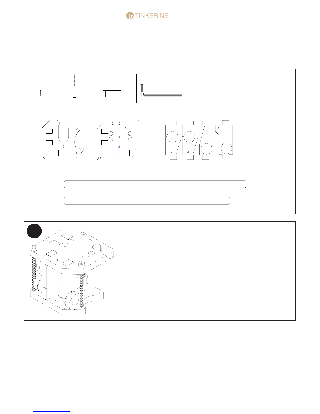
Parts Required
M3x10 Screw
x4
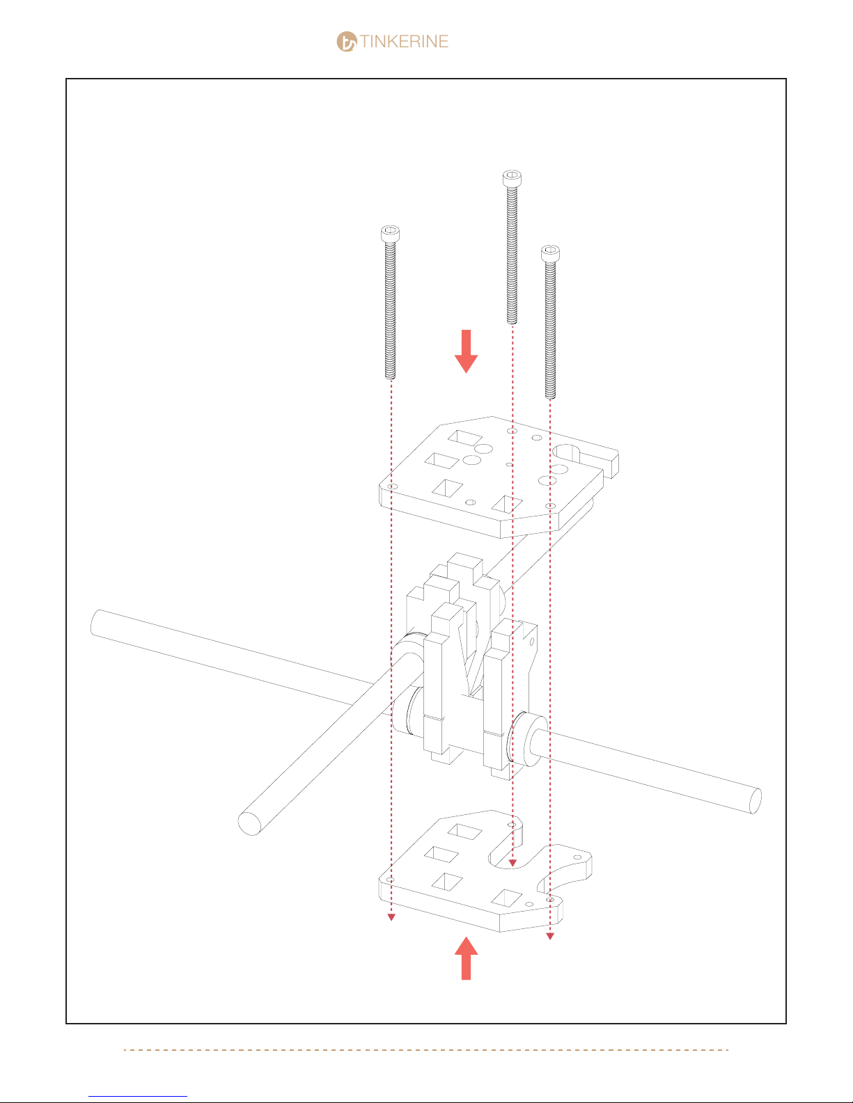
Carriage Bottom Carriage Top Linear Bearing Holder
M3x50 Screw
x3
X-Axis Carriage Smooth Rod (310mm)
Y-Axis Carriage Smooth Rod (280mm)
45mm Bearing
x2
Tools Required
M3 Allen Key
B
C
!
If your carriage comes to you partially assembled. Skip ahead to page 40 of
the assembly manual and follow the instructions listed for assembled units.
[email protected] | 1-604-288-877838
Page 39
TINKERINE
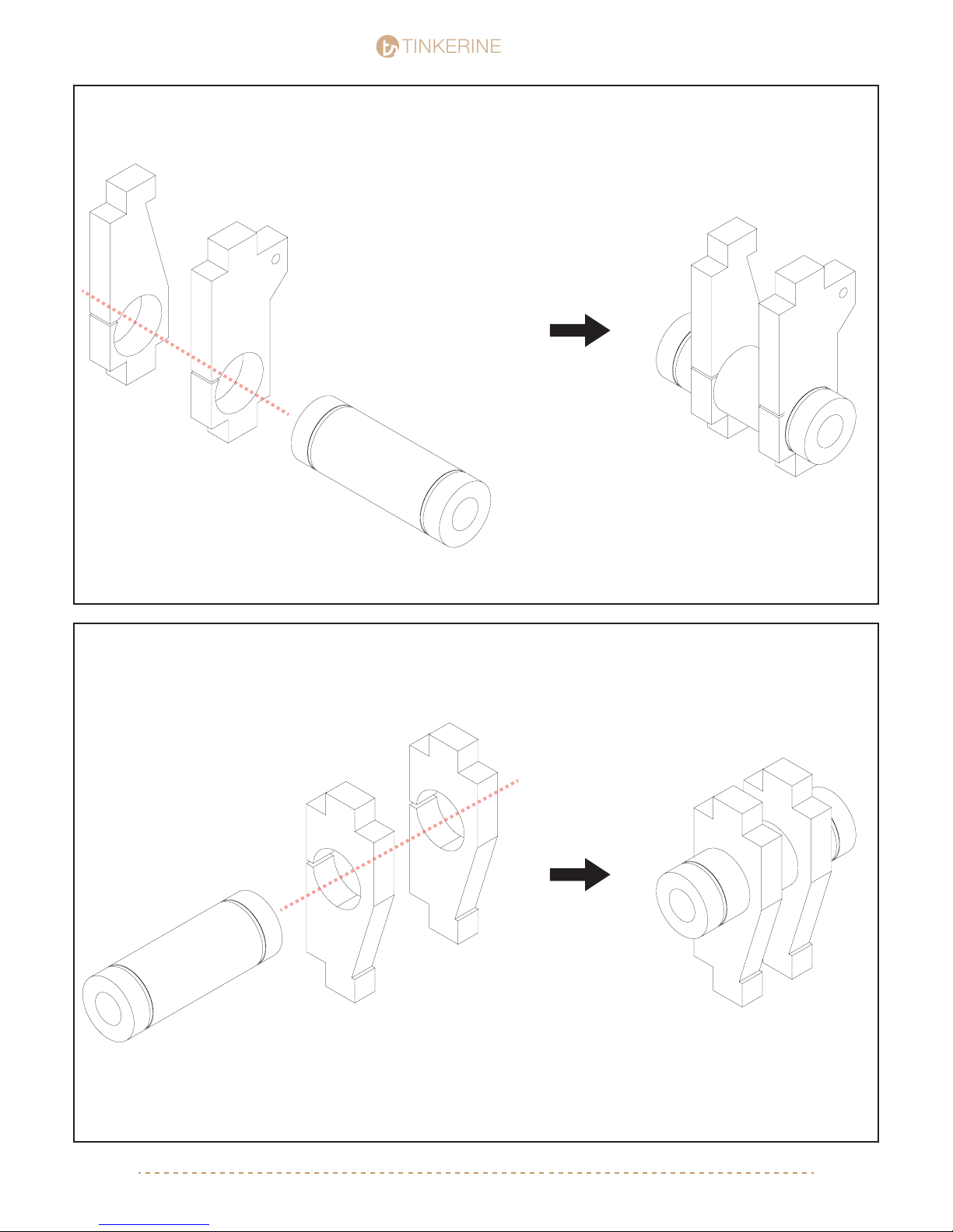
1. Carriage (X-Axis Bearing)
B
STUDIO
STUDIO
C
B
C
45mm Bearing
Carriage (Y-Axis Bearing)2.
45mm Bearing
A
A
A
[email protected] | 1-604-288-877839
A
Page 40
TINKERINE
3.
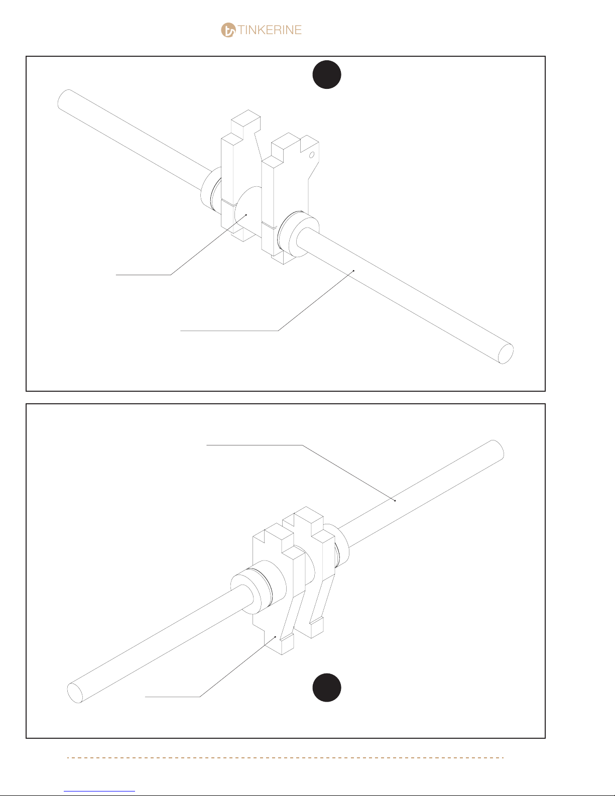
X-Axis Bearing
STUDIO
STUDIO
Take extra care when inserting the smooth
rod into the linear bearing. Go at it slowly
!
and make sure to not force the rod into
the bearing to prevent the ball bearings
from dislodging.
B
C
4.
X-Axis Cross Rod (310mm)
Y-Axis Cross Rod (280mm)
A
A
Y-Axis Bearing
Take extra care when inserting the smooth
rod into the linear bearing. Go at it slowly
!
and make sure to not force the rod into
the bearing to prevent the ball bearings
from dislodging.
[email protected] | 1-604-288-877840
Page 41
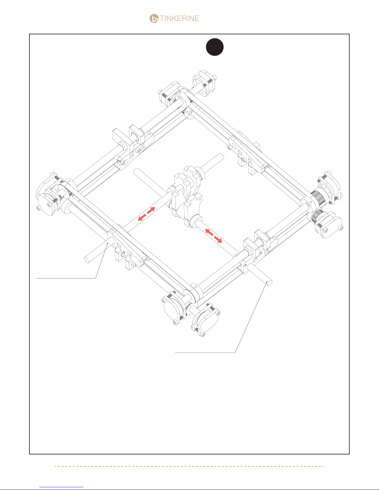
X-Axis Cross Rod (310mm)
Y-Axis Cross Rod (280mm)
TINKERINE
STUDIO
STUDIO
[email protected] | 1-604-288-877841
5.
The frame has been hidden to give you a clearer view. To insert the cross rods, one by one take the rods and
insert it into one end of the slider. Push the rod into the rst slider to give you enough room to bring the rod up
into the gantry so it becomes leveled with the second slider. Then retract the rod so it can be inserted into the
second slider.
For Pre-Assembled Carriage:
Position the carriage in the right direction (Arrow on assembly pointing toward back of printer), take any of the
two rods and insert it carefully into the respectively linear bearing. Bring the rod and carriage into the gantry
space, and insert one end of the rod into the slider, twist the rod while supporting the slider will help you move
the rods easier. Once you have enough clearance to insert the other of the rod into the slider, twist the rod again
to insert into the slider on the opposite side. Repeat with second rod.
B
A
A
C
Take extra care when inserting the smooth
rod into the linear bearing. Go at it slowly
and make sure to not force the rod into
the bearing to prevent the ball bearings
from dislodging.
!
Page 42
TINKERINE
6.
STUDIO
STUDIO
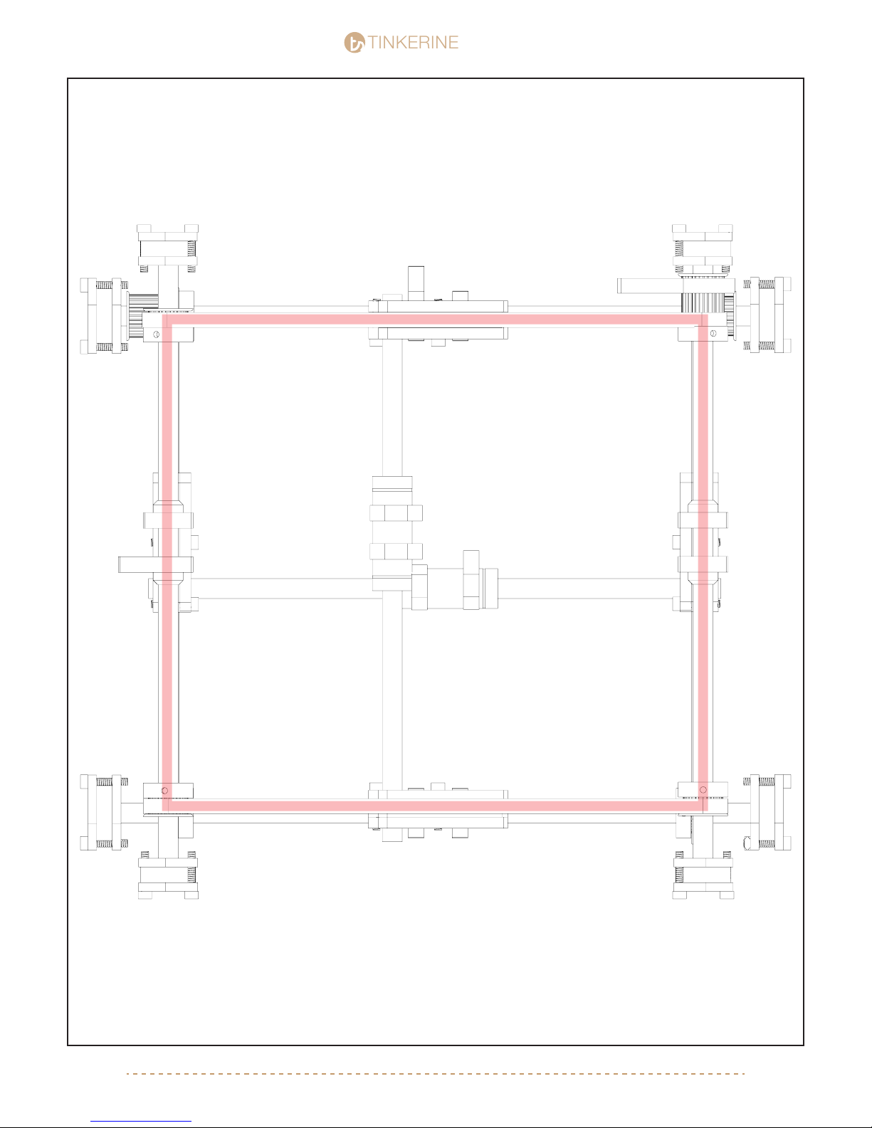
At this point this is what your gantry should look like from the top. Make sure to aligned the pulleys on both
sides of the belt so the belt is sitting parallel with the middle of the sliders. Tighten the sets screws on the
pulleys once you have aligned them all.
[email protected] | 1-604-288-877842
Page 43
Page 44
TINKERINE
8.
STUDIO
STUDIO
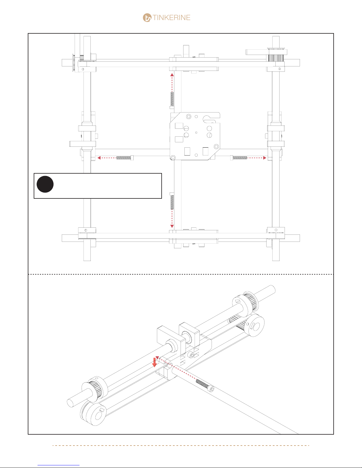
Newer versions of the Ditto+ 3D printer
will not require the belt tensioning
!
screws to be installed.
Insert the belt tensioning screws as shown into the four sliders. Refer to the image below to see a closer view.
Push down on the belt to create a gap so you can screw in the
M3x10 screw over the at surface of the belt. Turn until the screw
threads into the far side of the slider panel and the screw head is
ush with the slider.
M3x10 (x4)
M3x10
[email protected] | 1-604-288-877844
Page 45
TINKERINE
9.
STUDIO
STUDIO
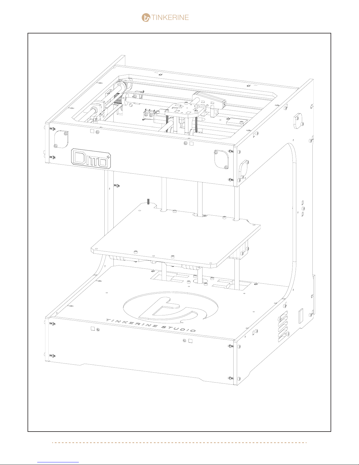
You’re almost done with the gantry assembly. For the most part you should now have a gantry system that you
can move manually by hand. Move on to part three of the gantry assembly to complete the gantry system.
[email protected] | 1-604-288-877845
Page 46
TINKERINE
Gantry Assembly pt.3
STUDIO
STUDIO
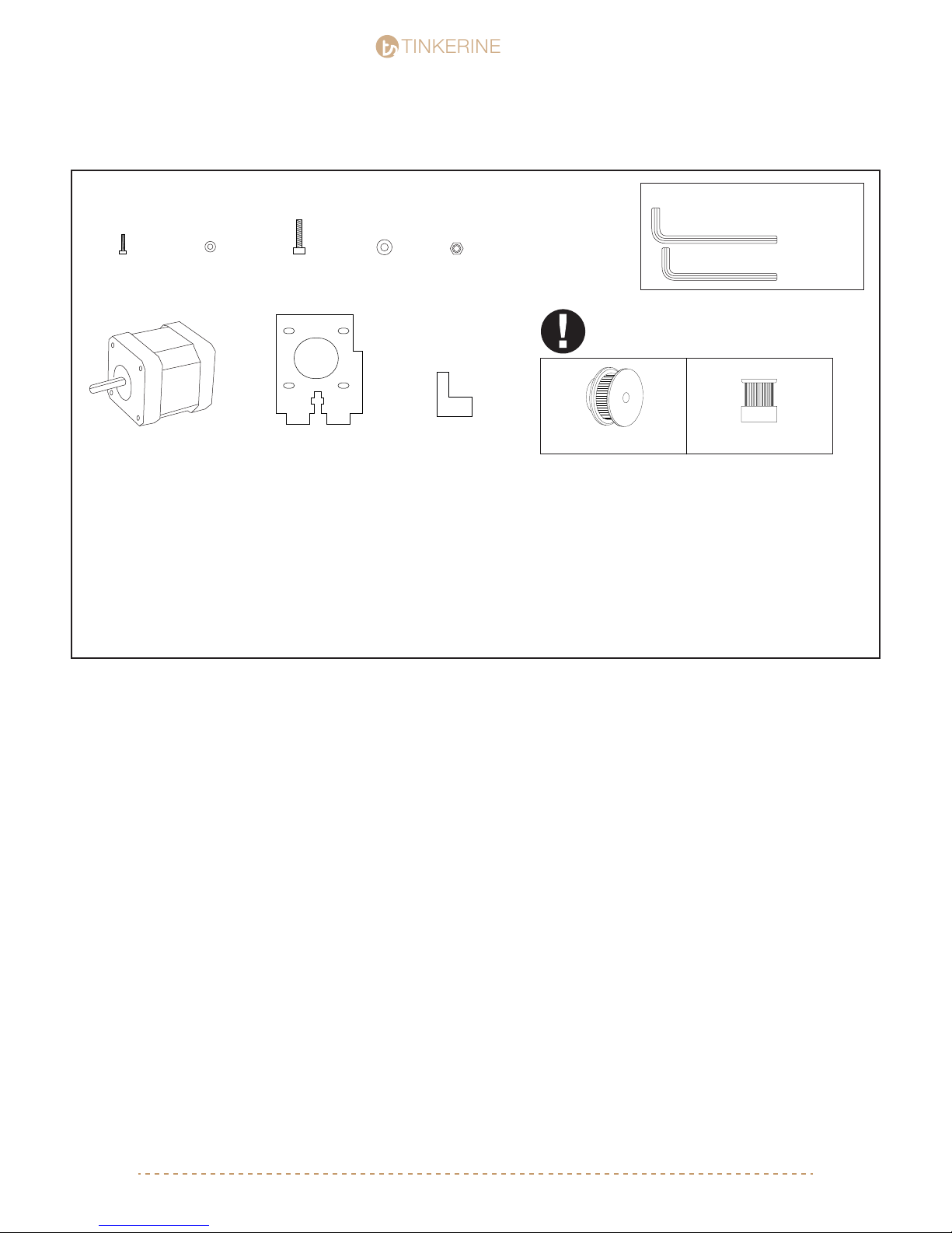
Parts Required
M3x10 Screw
x8
NEMA17 Stepper Motor
M3 Washer
x2
x8
M4x16 Screw
x1
Motor Bracket
M4 Washer
x1
M4 Nuts
x1
Motor Wedge
Tools Required
M4 Allen Key
M3 Allen Key
x2v.1 v.2 x2
36 Tooth Timing Pulley 18 Tooth Timing Pulley
If you received your Ditto+ Kit after 1/15/14
you may have v.2 timing pulley included in
the kit. Follow the instruction as per the v.1
pulley.
[email protected] | 1-604-288-877846
Page 47
TINKERINE
1.
STUDIO
STUDIO
M3x10 (x4)
M3 Washer (x4)
2.
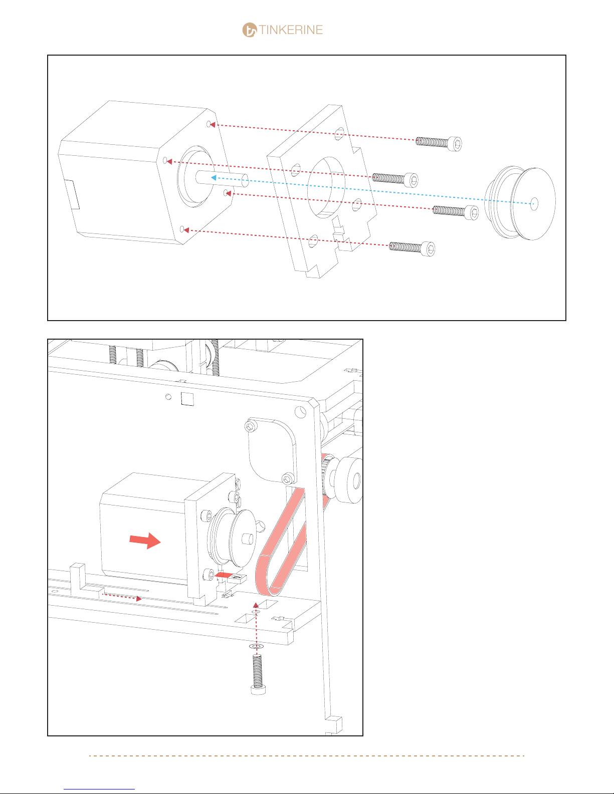
A. Fasten the motor bracket to the motor
and slide the pulley onto the motor shaft.
Lightly tighten the motor bracket screws as
you will need to make minor adjustments in
the second step.
B. Before inserting the motor bracket into
the slot on the frame, insert a M4 nut into
the T-slot.
C. Look the belt around the pulley and seat
the motor into the slot. You may need to
shift the motor foward or backward within
the bracket to make sure the belt is
tensioned and does not have extra slack.
Tighten the screws once the motor is in the
correct position.
D. Position the pulley so the belt is perpendicular and not angled in a way so that the
belt is rubbing against the pulley or the
wooden frame. Tighten the set screw of the
pulley on the at edge of the motor shaft
once you have positioned the pulley.
M4x16
M4 Nut + Washer
[email protected] | 1-604-288-877847
E. Insert the M4 screw from the bottom
and secure the motor bracket to the frame.
Insert the motor wedge to tuck it under the
other side of the motor.
F. Connect the 4-pin motor wire to the port
located on the bottom edge of the motor.
Page 48
TINKERINE
3.
M3x10 (x4)
M3 Washer (x4)
STUDIO
STUDIO
4.
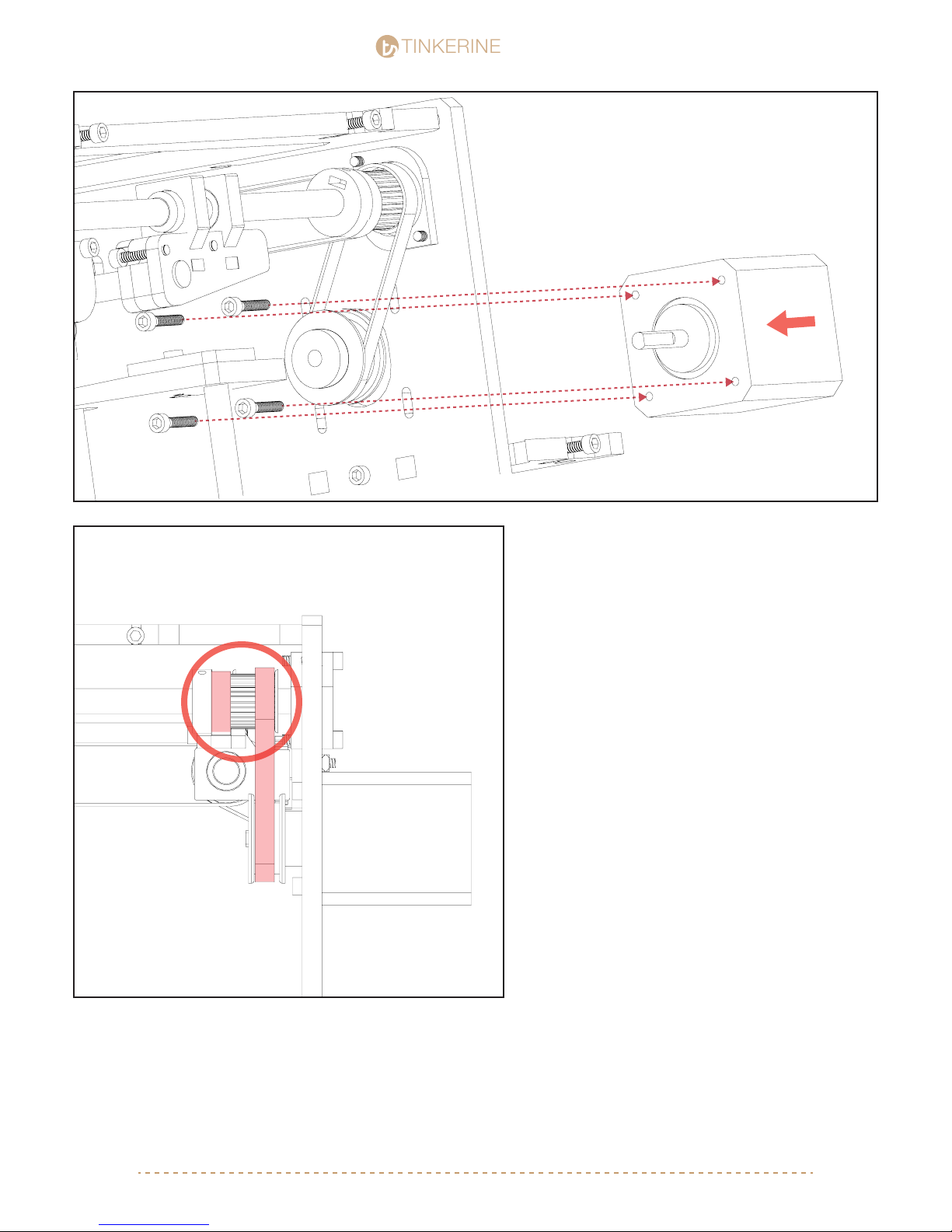
A. As shown in Step 3, insert the motor
from the back with the pulley already sitting
in the looped belt from the front. The
tapered end of the pulley should be
pointing away from the motor.
B. Insert the M3 screws to secure the
motor to the frame. Make sure to position
the motor on the frame at a point where the
belt is properly tensioned to avoid giving
the belt any slack.
C. Tighten the setscrew within the pulley
on the at edge of the motor shaft to
secure the pulley.
D. As shown in Step 4, take a minute to
ensure that all belt are properly aligned.
Belt should always sit perpendicular to the
pulley and should not be angled in any
way. Also make sure the the belt teeth is
fully seated into the grooves of the pulley
and not chewing into the walls of the
pulley. You may need to loosen the sets
screws on the pulley to re-adjust the
positions. Check all belts.
E. Connect the 4-pin motor wire to the port
located on the bottom edge of the motor.
[email protected] | 1-604-288-877848
Page 49
TINKERINE
5.
STUDIO
STUDIO
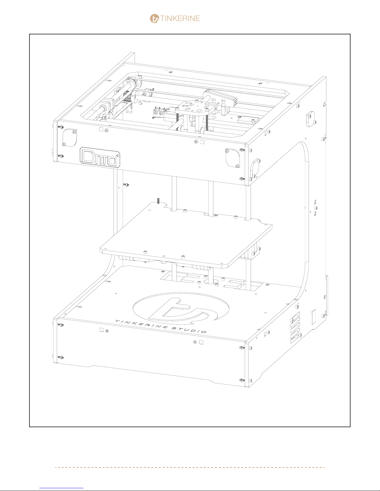
Your printer’s gantry system should be fully assembled now. You should be able to manually move the carriage
around on the X+Y axis. Double check to make sure all belts are properly secures + tensioned, and that all
setscrews are properly tightened.
[email protected] | 1-604-288-877849
Page 50
TINKERINE
Extruder Assembly
STUDIO
STUDIO
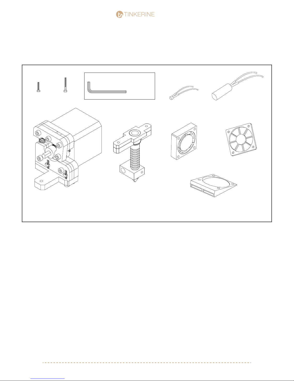
Parts Required
M3x16 Screw
x36
Extruder Assembly Hotend Assembly
M3x25 Screw
x2
Tools Required
M3 Allen Key
Electric Fan
x2
Ceramic Heater CartridgeThermistor
Fan Shield
x1
Fan Duct
x2
[email protected] | 1-604-288-877850
Page 51
TINKERINE
STUDIO
STUDIO
1.
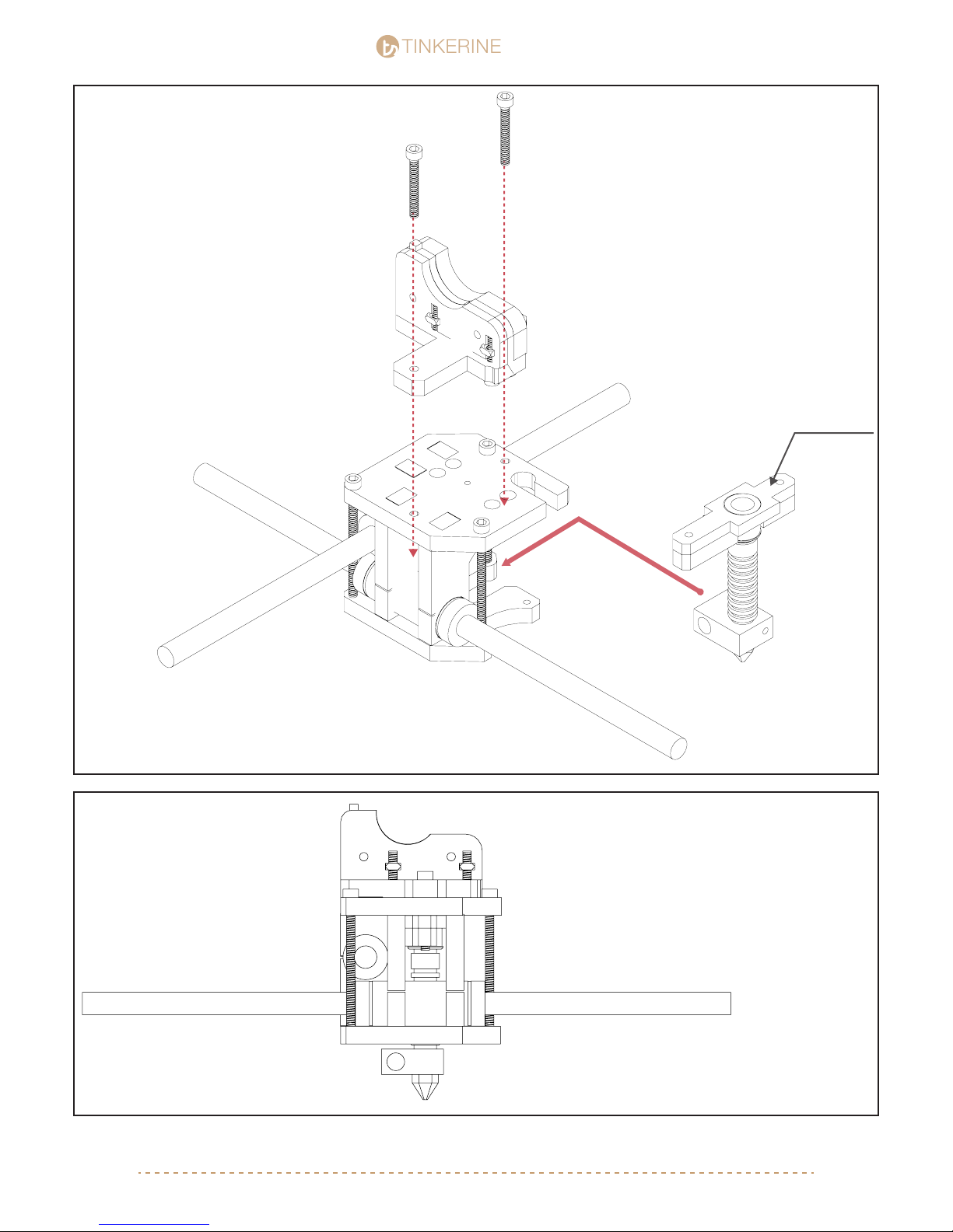
M3x25 (x2)
Place the bottom portion of the extruder onto
the carriage and insert the hotend + hotend
mount into the center of the carriage through
the slot located on the back on the carriage.
With the two M3x20 screws, secure the
extruder and hotend to the top plate of the
carriage. The screws should thread into the
hotend mount, securing all the components
together.
Ensure that the acrylic spacer is attached to
the top of the hotend and leave the ceramic
insulation wrapping attached to the hotend.
Acrylic Spacer
2.
Hotend + Hotend mount
From the front, your carriage should now look
like this. Make sure the larger portion of the
extruder is on the left side. The extended
portion of the hotend should also be pointing
toward the left.
[email protected] | 1-604-288-877851
Page 52
TINKERINE
3.
STUDIO
STUDIO
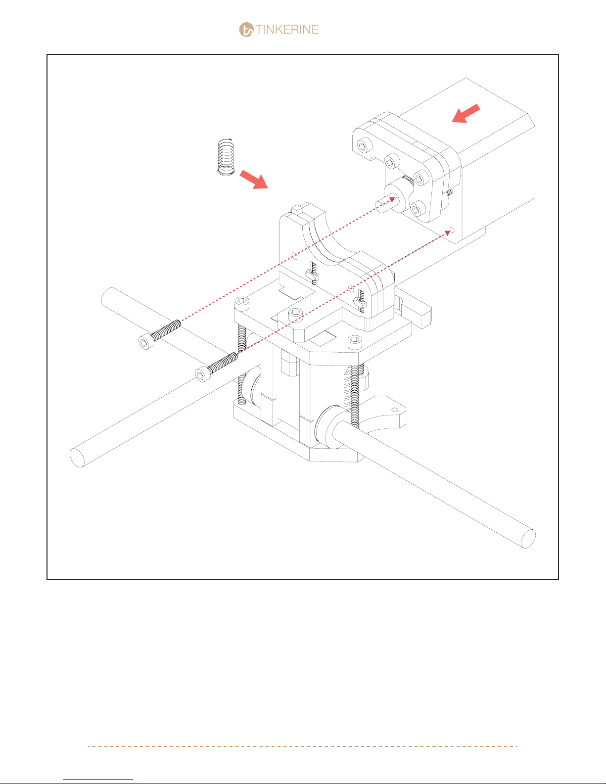
M3x16 (x2)
Now that the hotend and the bottom portion of the extruder is secured to the carriage, we’ll
now re-assemble the extruder. Place the spring back into the holder pin ( Package with
bed-leveling springs) and pinch it with the top portion of the extruder. Line up the mounting
hole and screw in the two M3 screws that we have removed earlier.
[email protected] | 1-604-288-877852
Page 53
TINKERINE
4.
STUDIO
STUDIO
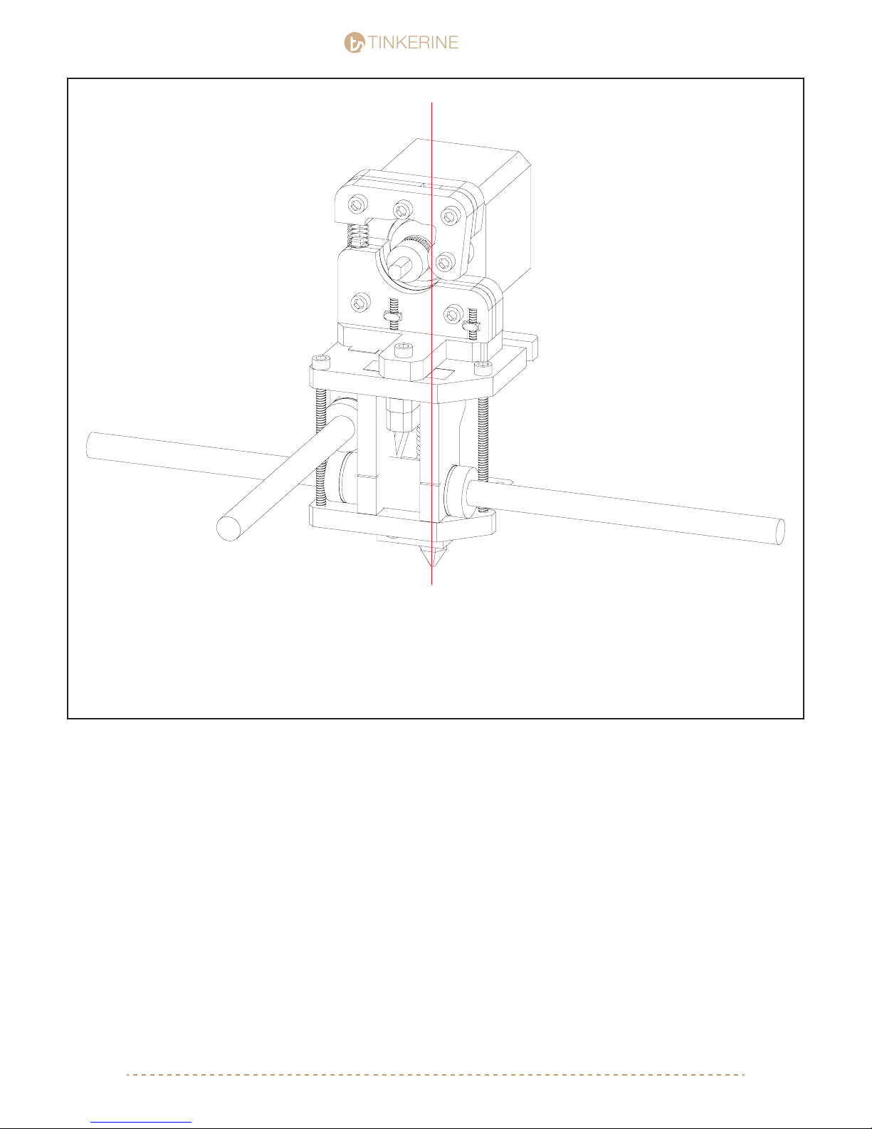
From the top of the extruder, look down and check that there is a clear path from the extruder to the nozzle.
The groove of the hobbed bolt should be positioned that it feeds into the hotend. If the aligment of the hob is
off, use a allen key to loosen the setscrew on the hob and reposition. Make sure to set the screw on the at
face of the extruder motor shaft.
[email protected] | 1-604-288-877853
Page 54
TINKERINE
5.
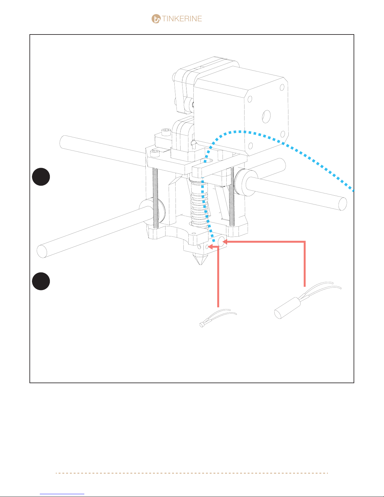
Your printer’s hotend may
already have the heater
!
cartridge and thermistor already
installed into the hotend. In this
case you will just need to route
the wires as shown.
STUDIO
STUDIO
Take extra care when tightening the
setscrew for the thermistor. Turn the
!
setscew very slowly as the glass on the
thermistor will crack if there is too much
pressure applied. There just needs to be
enough force applied so the thermistor
does not slide out of its slot.
On the back face of the hotend, there will be two slots. The large of the two slot will be for the heater cartridge,
and the smaller one is designated for the thermistor. Insert the heater cartridge and therminstor into their respective slots and secure them in place using the setscrews located on the sides of the hotend. Once the thermistor
and heater cartridge are in place, route the wires into the wire guide shown in the picture (blue path).
Themistor
Heater Cartridge
[email protected] | 1-604-288-877854
Page 55
TINKERINE
6.
STUDIO
STUDIO
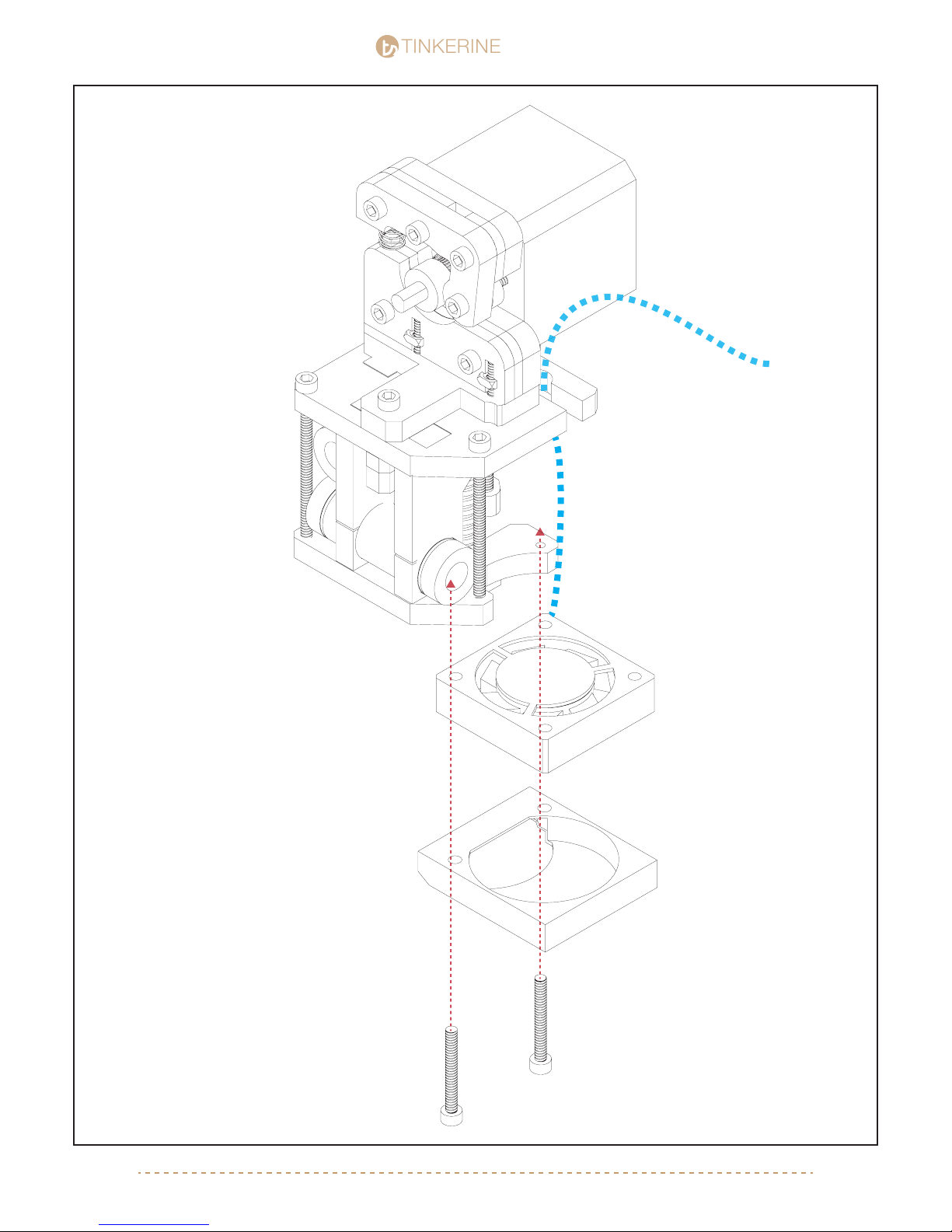
To install the print bed fan, grab a fan and
point the sticker side downward. Orientate
the fan so the wire is pointing toward the
back of the printer, doing so will give you
cleaner look when you are performing wire
management. Similar to the wires for the
hotend, route the fan wire up the wire guide.
It is recommended that you mark the ends of
the wire so you are able to distinguish the
separate fans during the wire connection
process.
Insert the M3 screw through the bottom of
the air duct and fan, there are two mounting
holes on the bottom of carriage. The mouth
of the fan duct should be point toward the
M3x20 (x2)
[email protected] | 1-604-288-877855
Page 56
TINKERINE
7.
STUDIO
STUDIO
M3x16 (x2)
M3 Nut (x1)
1
2
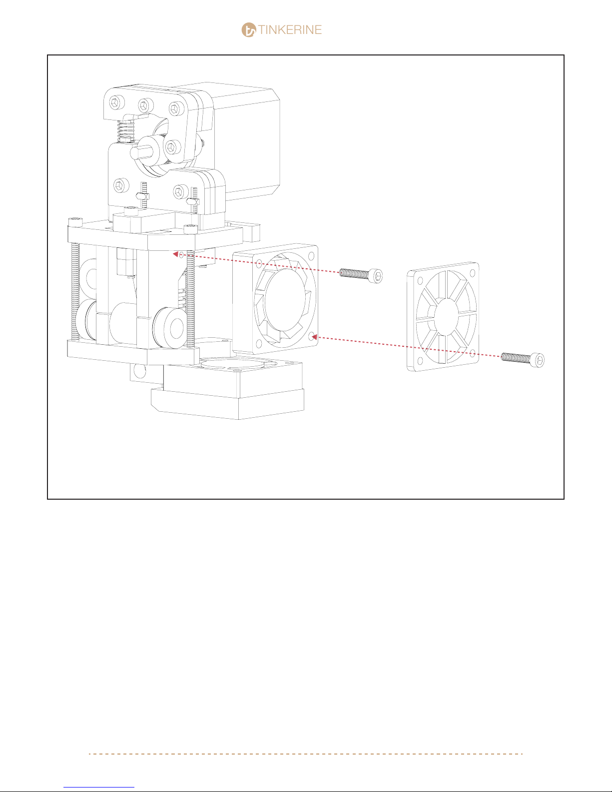
To install the hotend cooling fan, grab the fan and point the sticker side toward the hotend. The fan should sit
between the two carriage plates so if it does not t, you will need to loosen the carriage screws. Route the fan
wires so that it comes out of the top right corner and sits in front of the fan and wire guide. Secure the fan to the
carriage with screw 1 and attach the fan guard to the with screw 2 + M3 Nut.
[email protected] | 1-604-288-877856
Page 57
TINKERINE
8.
STUDIO
STUDIO
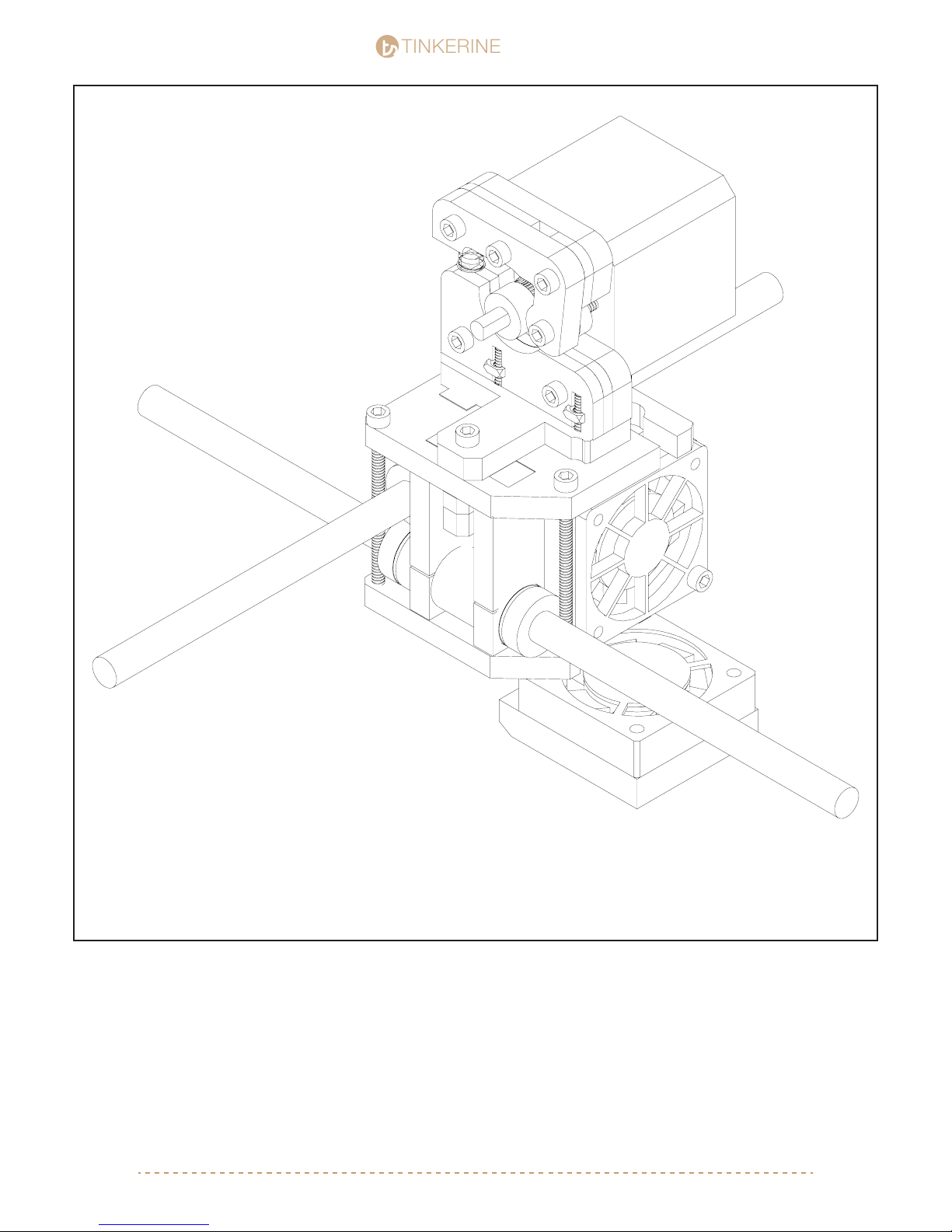
You have completed the extruder and fan assembly. Double check to make sure all the fans are facing the right
way and that all the wires are properly routed to go up the wire guide. All components on the carraige (hotend,
motor, fan) should be properly secured and tightened. Connect the 4-pin motor wire to the extruder motor.
[email protected] | 1-604-288-877857
Page 58
TINKERINE
9.
STUDIO
STUDIO
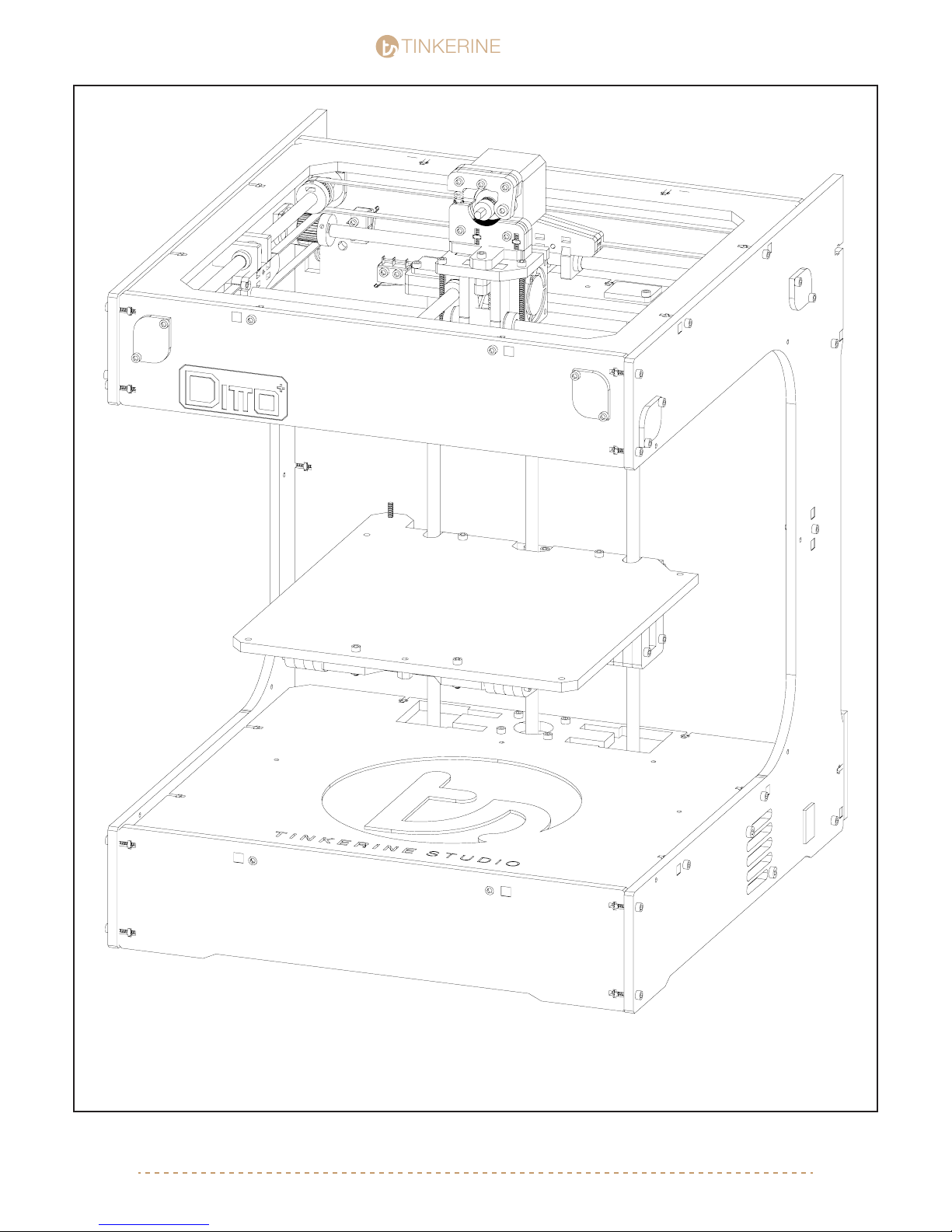
You are almost done assembling your printer. Move on to the next step to install the power supply and
electronics to the printer.
[email protected] | 1-604-288-877858
Page 59
TINKERINE
STUDIO
STUDIO
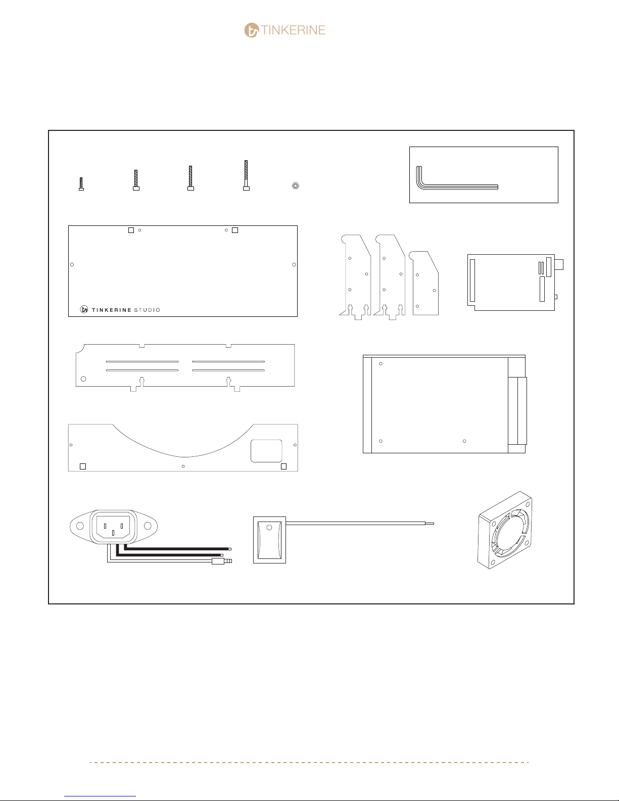
Electronics / Spool Holder Assembly
Parts Required
M3x10 Screw
x2
M3x16 Screw
x13
M3x20 Screwx3M3x25 Screw
Motor Compartment 1 of 2
Motor Compartment 2 of 2
x2
M3 Nuts
x20
Spool Holder
Tools Required
M3 Allen Key
ARDUINO
Arduino Mega 2560
Back Bracket
Electric Socket
Power Switch
Power Supply
50mm Electric Fan
x1
[email protected] | 1-604-288-877859
Page 60
TINKERINE
1.
STUDIO
STUDIO
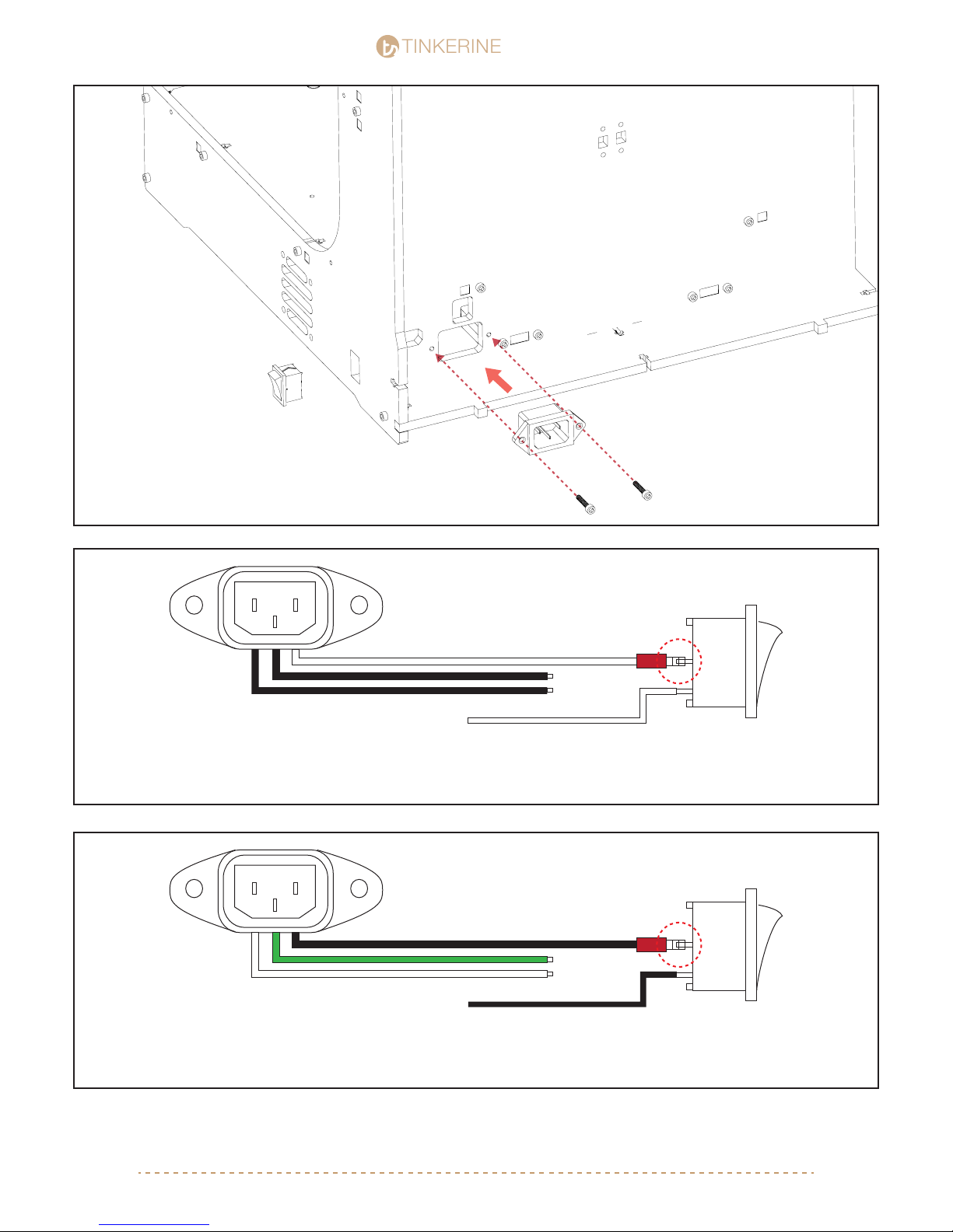
Insert the power socket and power switch as shown. The power
switch is pressure tted and the power socket will need to be
secured by two M3x16 screw + M3 nut.
Older Versions
N
L
G
M3x16 (x2)
M3 Nut (x2)
G
N
L
Connect the L line (White) from the power socket to the middle prong on the power switch. Leave the other
wires along for now as they will be connected to the power supply later.
Newer Versions
N
L
G
Connect the L line (Black) from the power socket to the middle prong on the power switch. Leave the other
wires along for now as they will be connected to the power supply later.
G
N
L
[email protected] | 1-604-288-877860
Page 61
TINKERINE
2.
50mm Fan
STUDIO
STUDIO
M3x20 (x2)
M3 Nut (x2)
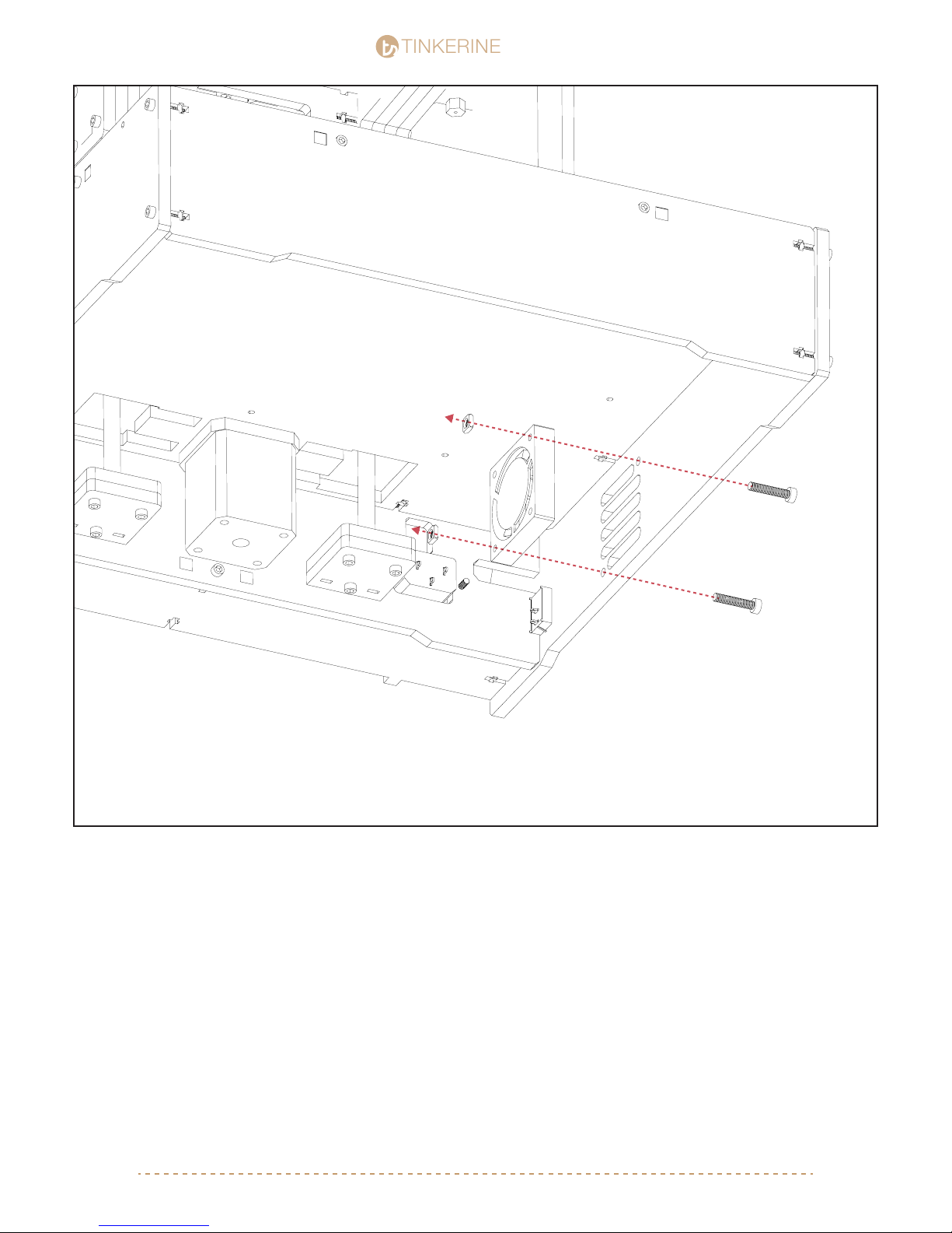
Secure the 50mm fan to the back side of the air intake grill. The sticker face of the fan should point toward the
center of the printer. Secure the fan to the frame with two M3x20 screws + nuts
[email protected] | 1-604-288-877861
Page 62
TINKERINE
3.
M3x10 (x2)
STUDIO
STUDIO
M3x25 (x2)
M3 Nut (x2)
110v <> 220v
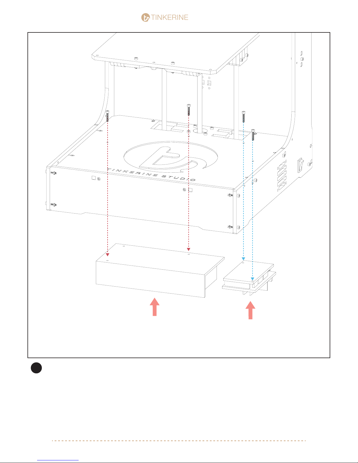
Secure the power supply and Arduino board to the bottom of the face plate. You will need to use M3 nuts to
secure the Arduino board. Orientate the power supply so the port are pointing toward the Arduino, and orientate
the Arduino board so the USB ports are pointing toward the back of the printer.
The power supply is set to 110v by default for use in North America. To use 220v (Europe), follow the instruc-
!
tion on the power supply to ick the switch to 220v.
[email protected] | 1-604-288-877862
Page 63
TINKERINE
4.
STUDIO
STUDIO
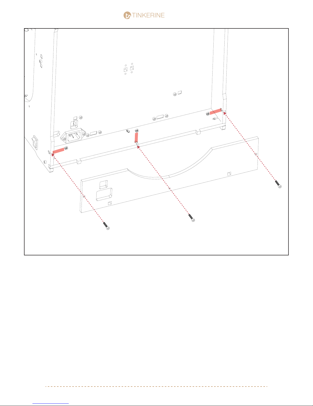
M3x16 (x3)
M3 Nut (x3)
After the power socket is in place, install the outer bracket by securing it with the T-slots shown in the picture.
[email protected] | 1-604-288-877863
Page 64
TINKERINE
6.
STUDIO
STUDIO
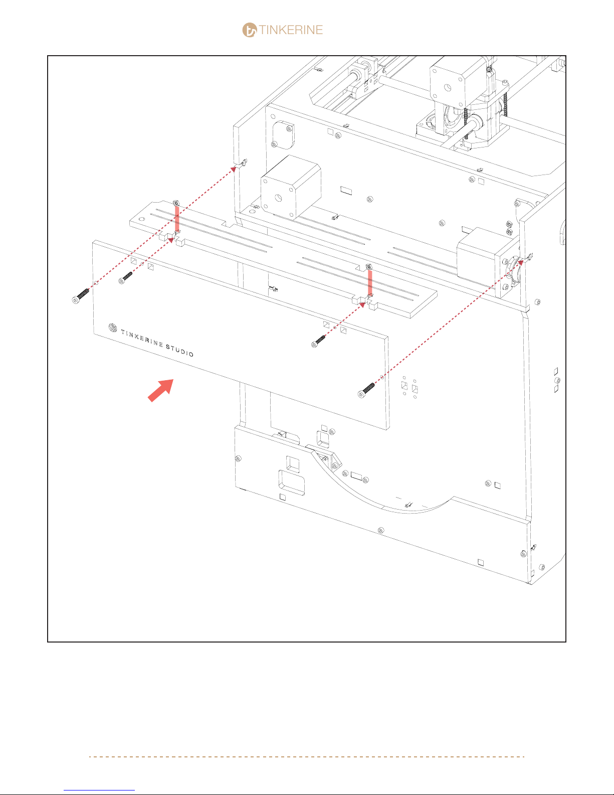
M3x16 (x2)
M3 Nut (x2)
M4x20 (x2)
M4 Nut (x2)
The back motor cover is composed of two pieces, assemble and secure with the two T-Slots on the top edge.
The motor cover is then secured with two T-Slots on the sides. The nuts on the side will require more effort to
push in as they were intended to be pressure tted. You can choose to leave the motor cover off for now as we
will require access to thread in the lament guide tube later on.
[email protected] | 1-604-288-877864
Page 65
TINKERINE
STUDIO
STUDIO
7.
M3x20 (x3)
M3 Nut (x3)
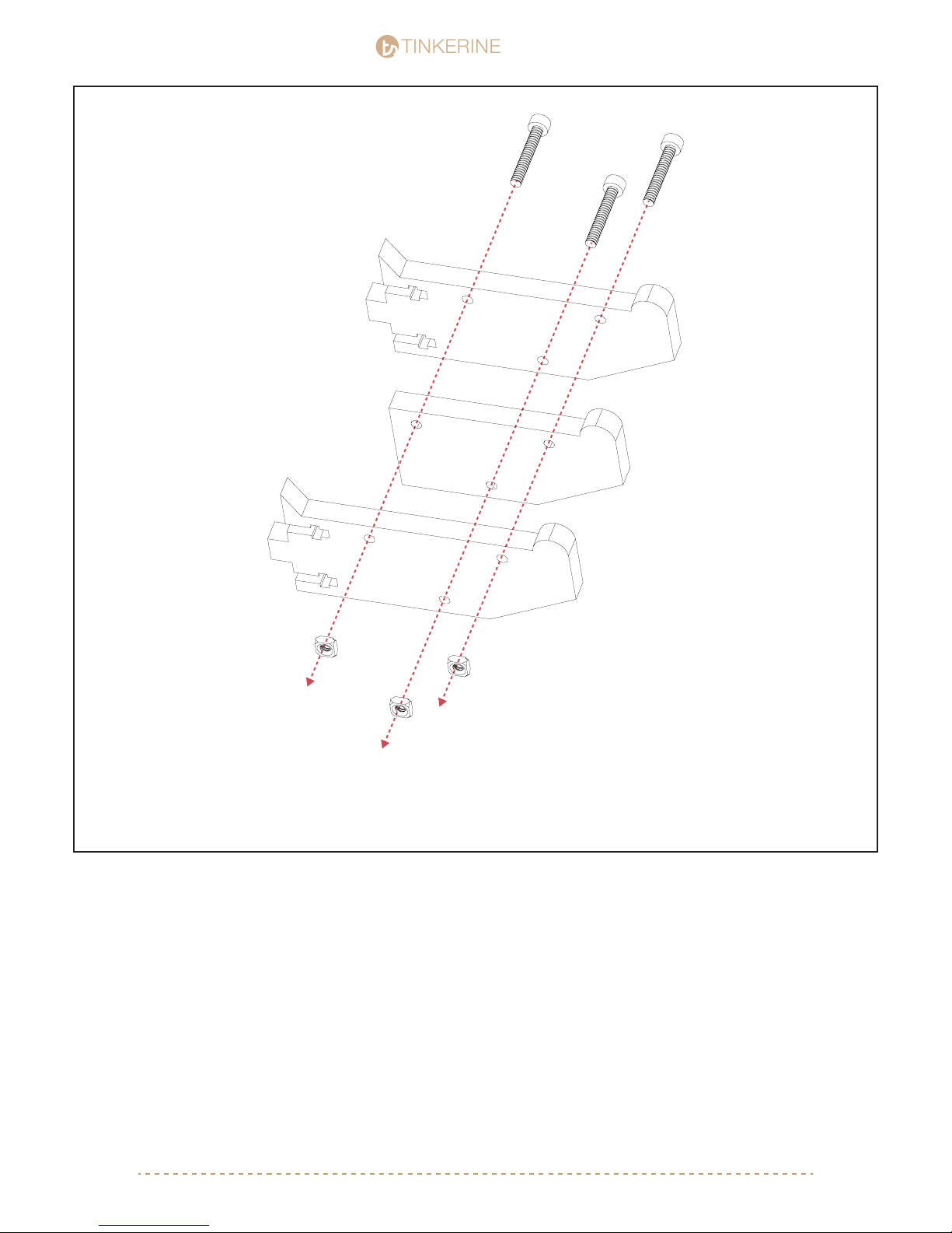
To assemble the spool holder, sandwich the smaller of the three spool holder pieces with the other two and
secure it with the M3 screw and M3 nut. Do not tighten this yet as it will make it hard to insert the assembly into
the main body.
[email protected] | 1-604-288-877865
Page 66
8.
TINKERINE
M3x16 (x4)
STUDIO
STUDIO
M3 Nut (x4)
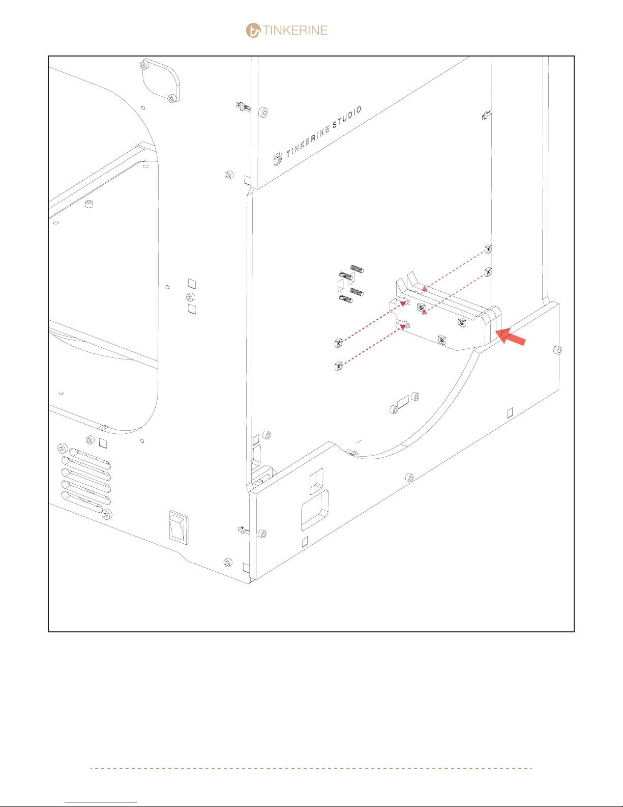
Insert the spool holder assembly to the frame and secure the spool holder with four M3 screws inserted from the
front side of the printer. Tighten all screws.
[email protected] | 1-604-288-877866
Page 67
TINKERINE
Print Bed Assembly
STUDIO
STUDIO
Parts Required
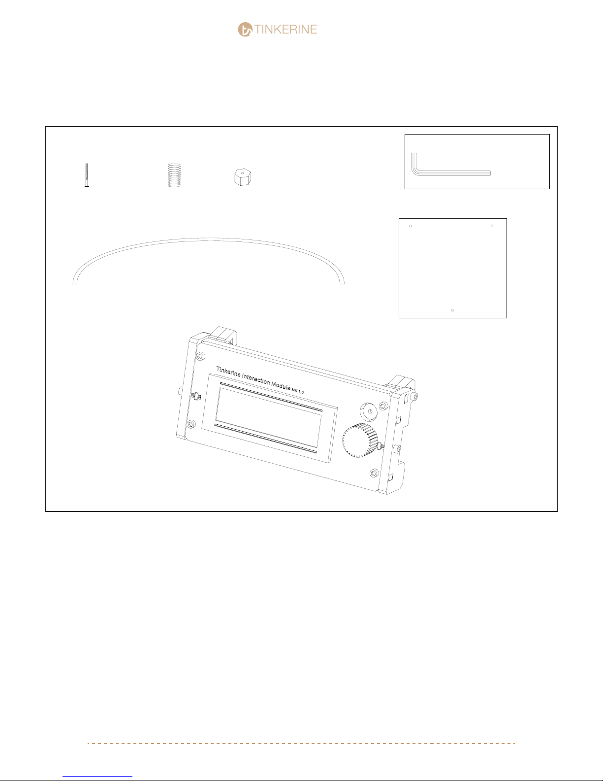
M3x25 Flathead Screw
x3
Calibration Springs
x3
Filament Guide Tube
Tools Required
M3 Allen Key
Thumb Nut
x3
Print Bed
T.I.M LCD/SD Controller
[email protected] | 1-604-288-877867
Page 68
1.
TINKERINE
STUDIO
STUDIO
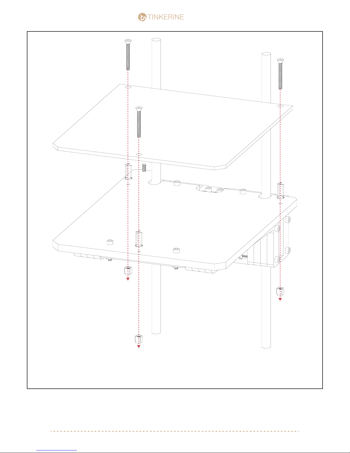
M3x25 Flathead Screw (x3)
Calibration Sping (x3)
M3 Thumb Nut (x3)
One by one, place a spring between the print bed and the wooden platform (beveled hole side up). Insert the
athead M3x25 screw from the top and secure it with a thumb nut. Repeat until you have all three points
secured. Turn the thumb nut to tension the spring, idealy you will want the spring to be compressed so the bed
is rmly planted onto the platform.
[email protected] | 1-604-288-877868
Page 69
TINKERINE
2.
STUDIO
STUDIO
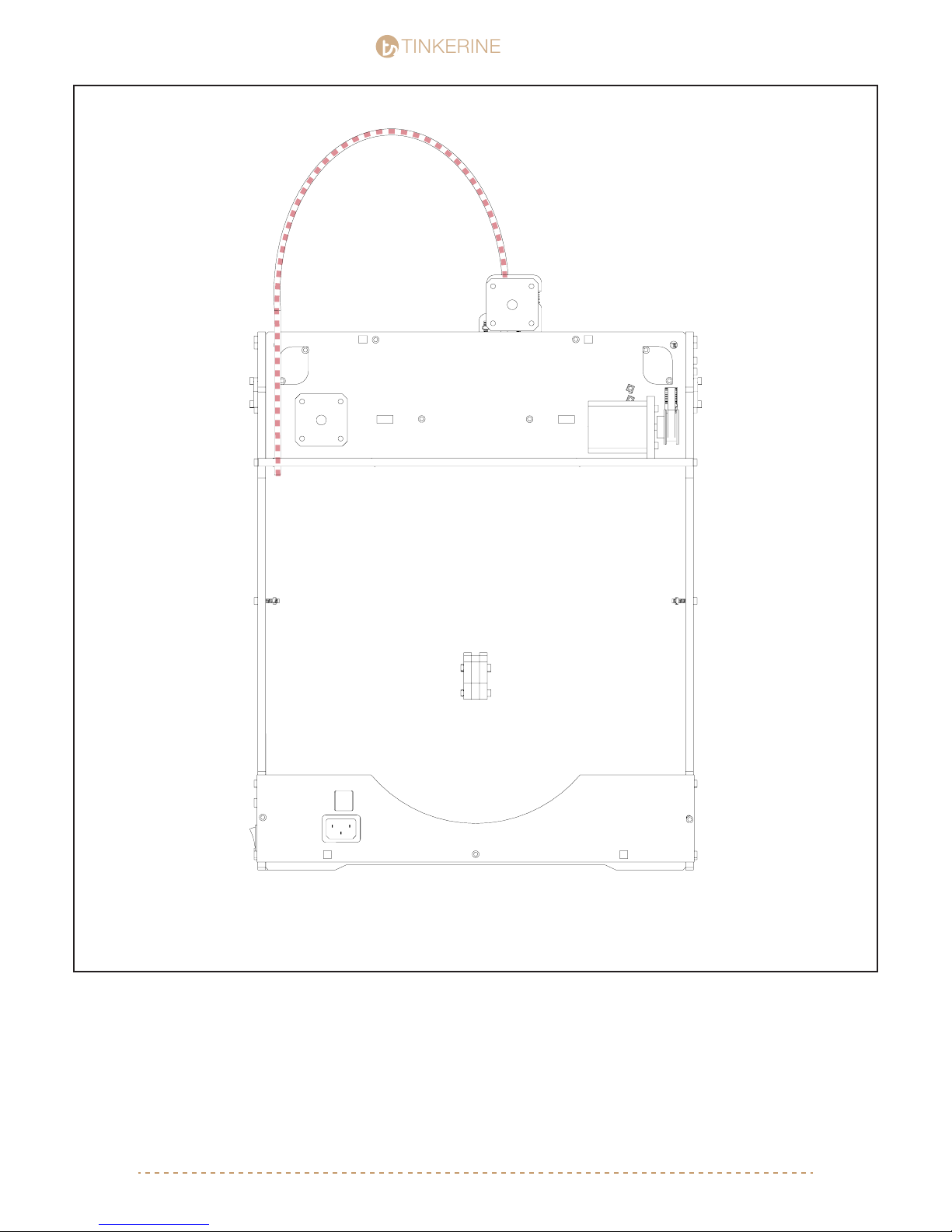
Take the lament guide tube and thread it through the cut out located on the corner of the motor cover and
motor bracket. Insert the other end into the top of the extruder. Remove the motor cover by unscrewing the two
M4x20 screw to thread the guide tube through more easily.
[email protected] | 1-604-288-877869
Page 70
TINKERINE
3.
STUDIO
STUDIO
A
B
SD CARD
SLOT
Potentiometer (Contrast)
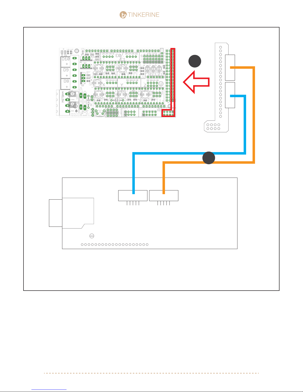
To install the T.I.M LCD controller to Ditto:
1. Connect the Smart Adapter onto the Aruduino board.
2. Connect the ribbon cables from the Smart Adapter to the back of the LCD control unit as shown above.
BACK OF LCD PANEL
[email protected] | 1-604-288-877870
Page 71
TINKERINE
3.
STUDIO
STUDIO
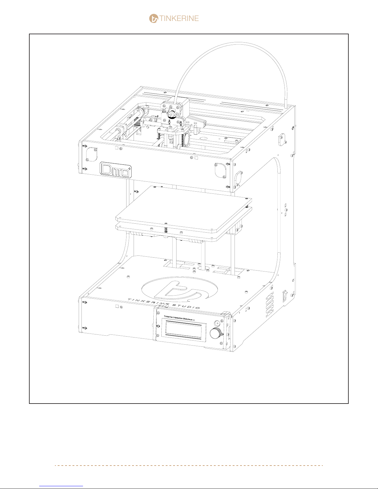
You’ve nished assembly your very own 3D printer (well almost!). With all of the components in the printer, move
on to the next step to begin the wiring portion of the assembly.
[email protected] | 1-604-288-8778 71
Page 72
TINKERINE
Wire Management
STUDIO
STUDIO
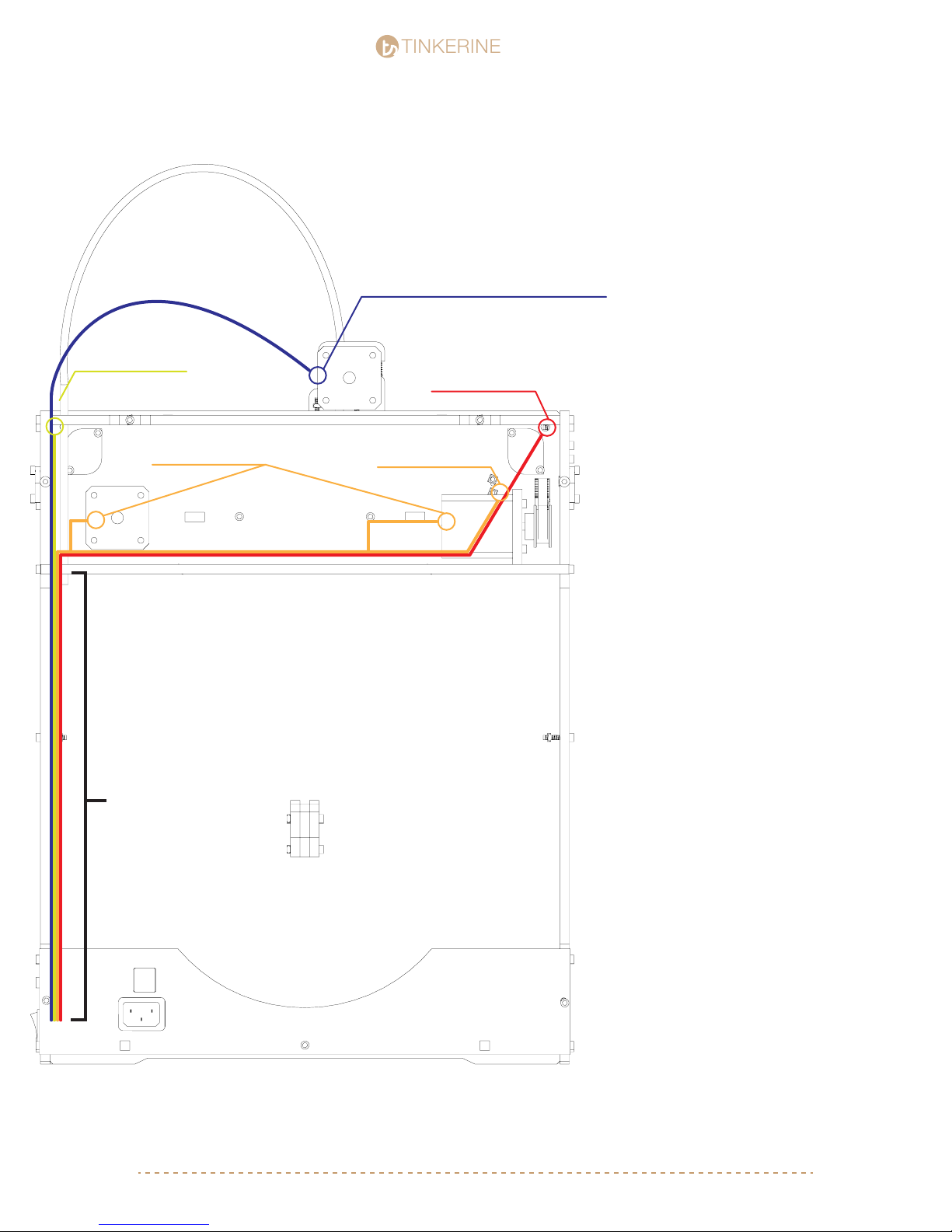
Right Side LED Wire
X-Axis Motor Wire
Y-Axis Motor Wire
Fan, Thermistor, Heater Cartridge, Motor Wire
Y-Axis Endstop Wire
Left Side LED Wire
X-Axis Endstop Wire
Z-Axis Endstop Wire
1. Route the wires from the Left Side LED,
X+Y+Z-Axis Endstop, X+Y Motor wire
through the wire holes from the front side
of the machine to the back. Route the wire
so it runs behind the Y-Axis motor and
underneath the X-Axis motor. Run all wires
through the hole located on the back
corner of the motor bracket.
2. Gather all the wires from the carriage
fan, heater cartrige, thermister, Right Side
LED, and extruder and route the wires
through the hole located on the motor
bracket.
3. You may choose to label the wires with
masking tape before you route them
through the hole located on the bottom
right corner of the printer. This will help you
indentify the wires later on.
NOTE 1: For the wires coming from the
extruder units, make sure to leave enough
slack so the wires still have some slack
once the extruder moves to it’s homing
location (Front left corner).
Large Wire Sleeve
NOTE 2:
Once the wires are all routed and connected to the electronics, use the supplied wire
sleeve to clean up the exposed wires on
the back and top of the machine. Use the
larger sleeve for the back portion of the
machine and the smaller wire sleeve to
wrap the wires coming from the extruder.
NOTE 3
After you have nished sleeving all the
wires and have conrmed that all electronic
components are in working order. Use the
supplied zip-ties to secure the ends of the
wire sleeve.
[email protected] | 1-604-288-877872
Page 73
TINKERINE
STUDIO
STUDIO
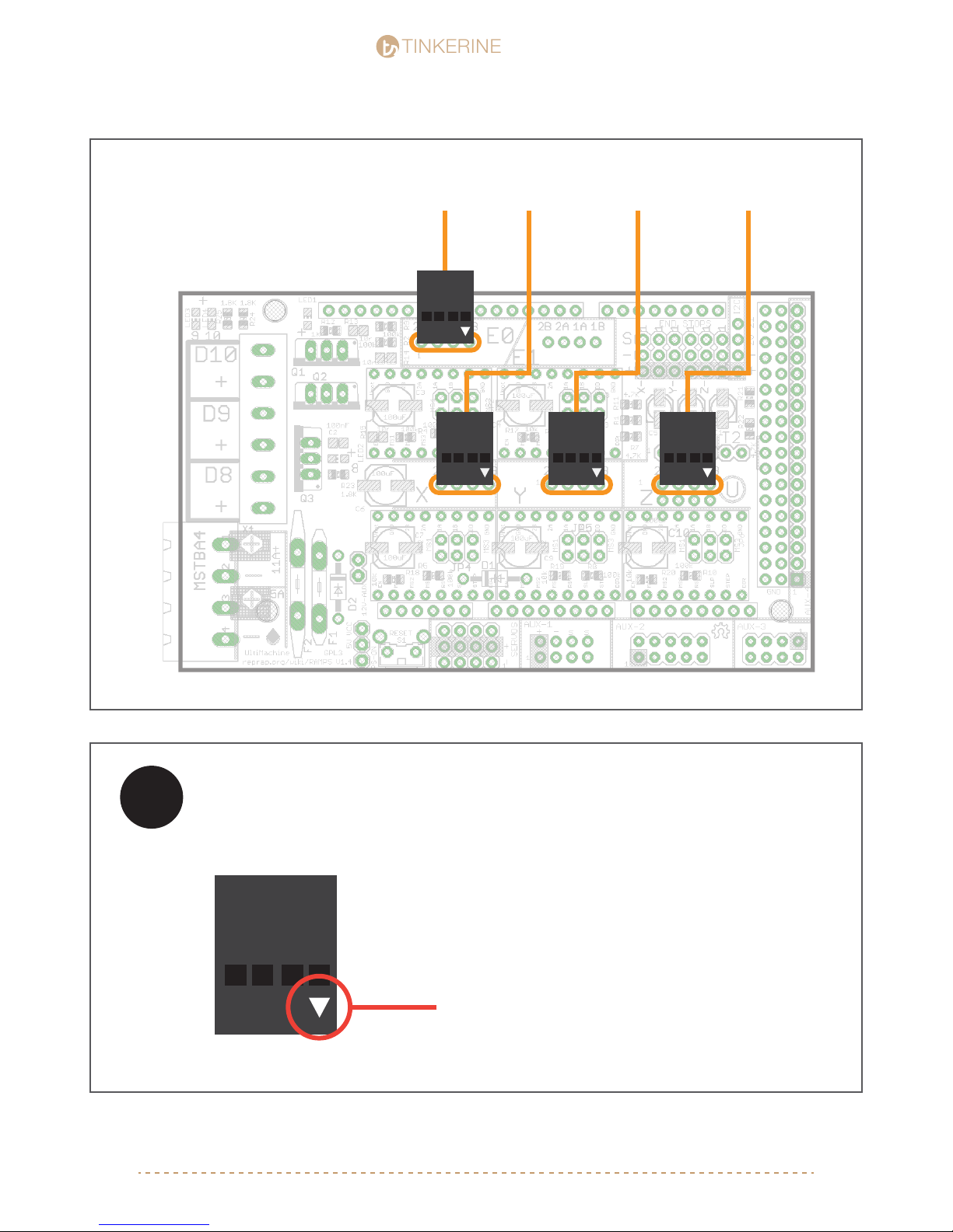
Extruder Motor
X Motor
Y Motor Z Motor
!
IMPORTANT
There is a small triangle on the rightmost side. Make
sure it aligns as shown in the diagram. If there is no
marking on the housing, face the exposed pin side
toward the electronics cooling fan.
[email protected] | 1-604-288-877873
Page 74
TINKERINE
STUDIO
STUDIO
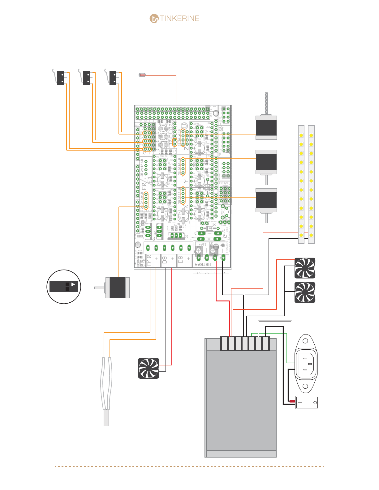
X Endstop
Y Endstop
Z Endstop
Thermistor
LED Strips
X Motor Y Motor Z Motor
*After you have thread the endstop
wires through the black plate, attach
the pins into the connector housing
before you plug them in.
Extruder Motor
(Print Bed)
Cooling Fans
Heater Cartridge
RAMPS 1.4
-
-
+
+
Heated Bed
Gnd
Cooling Fans
(Hotend + Electronics)
L
N
NG
L
Power Socket + Switch
*Negative ends of the wire that do not have
connector pins are marked with a black ink
on the ends*
Power Supply
[email protected] | 1-604-288-877874
Page 75
TINKERINE
STUDIO
STUDIO
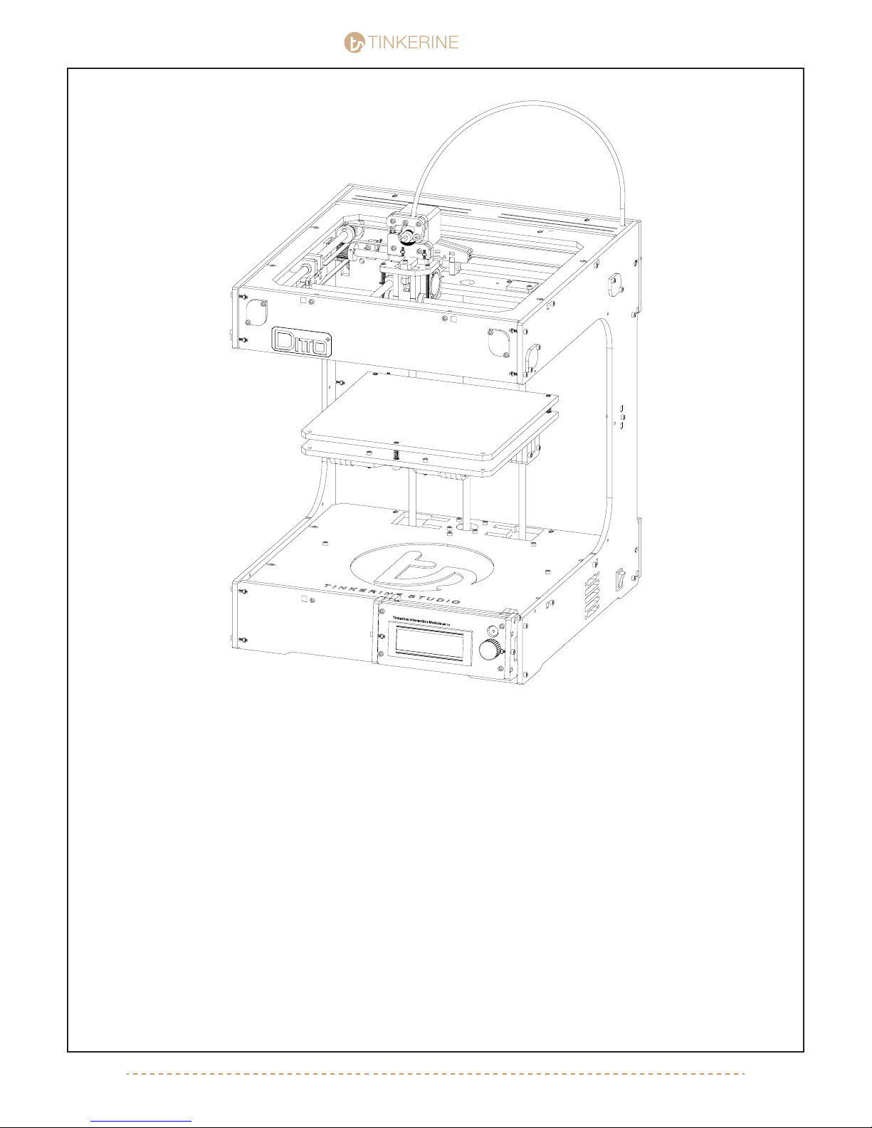
That’s it! You have just nished assembling your very own Ditto 3D printer. However there are just a few things to
check before you power-up the printer for the very rst time:
1. Make sure all screws and components are properly screwed down and secured.
2. While manually moving the the gantry system (extruder, belts, pulley, smooth rods, bearings), all components
should operate smoothly and not interferre with one another. Check that all sets screws on the pulley are
tightened, and all belts are aligned so they are seating fully in the teeth of the pulley.
3. All electronics are properly plugged in and seated into their correct ports. Make sure there are no exposed
wires in contact with electronic components, and the electronic cooling fan is properly mounted and directing
airow to the A4988 Stepper Driver.
4. Make sure there is no foreign objects along the path of moving components. Avoid using lubricant on the
linear bearing (Z Axis + Carriage). Most lubricants (especially ones that contain propellants) might absorb dirt
and become more viscous over time, which can cause more friction and cause damage to the bearings.
[email protected] | 1-604-288-877875
Page 76

TINKERINE
STUDIO
STUDIO
Preliminary Run-Through
Stage 1
1. Plug in the printer. Do not turn on the printer yet.
2. Connect the USB from the printer to the USB port on your computer. If you have an LCD/SD card unit,
connect it to your printer.
3. Test the X-Axis endstop. Manually move the carriage by hand and push it to the left side of the printer and
check to see if the slider will trigger the endstop. You will hear a click when enstop is trigger. Repeat the test
with the Y-Axis Endstop. If the endstop does not trigger, you will need to re-adjust the position of the endstop
so it makes contact with the trigger pieces on the slider.
4. Tighten the thumb screws underneath the print bed springs. This will tension the springs and prevent the
bed from moving around during printing.
5. Test the Z-axis endstop. Manually turn the lead screw to bring the bed upward. As the bed approaches the
nozzel, adjust the Z-axis trigger screw located on the back corner of the printer bed so that it makes contact
with the endstop lever before the nozzle touches the surface of the bed. The ideal distance between the nozzle
and print surface should roughly be the thickness of a piece of paper.
6. Calibrate the print bed. Using the 3-point leveling system, manually move the hotend to the each of the four
corners on the print bed. At each of the four point, adjust the thumb screws so the bed is evely leveled on all
sides.
Stage 2
1. Turn on the printer.
2. Check that both LED light strip are lit.
3. Check that the hot-end cooling fans are on and directing airow to the hot-end within the carriage unit.
4. Check that the electronics cooling fans are on and directing airow to the Arudino + A4988 Stepper drivers.
5. Check that the print bed cooling fan isn’t on. The fan for the print bed should only activate during printing.
6. If the LED or fan do not turn on, turn off the printer and disconnect the power source. Check your wiring to
see if all wire are properly seated and secured in their sockets.
Stage 3
1. Using Coordia (Control Software) or the T.I.M Controller, connnect to the printer and test move each axis.
2. Home all axis. If the printer triggers any of the endstop but doesn’t stop, shut off the printer immediately.
Check the enstop pin connector to see if the pins are fully seated into the housing, then make sure the housing
are properly connected to the pins on the electronics board. Since the X and Z axis endstop are grouped
together, there might be a chance that you have them plugged in reversed.
3. Using Coordia or T.I.M, set the preheat temperature for PLA (180c). Monitor the temperature level and check
that the heater cartriged and thermistor is working properly. If the hotend does not heat up, check that the
heater cartrige and thermistor is plugged in correctly. Do not touch hotend with your nger to check the
temperature as the cartridge can be functioniing correctly while the thermistor is providing a false reading.
4. Your printer is ready to start printing. Follow the calibration guide to start printing your rst object!
[email protected] | 1-604-288-877876
 Loading...