

Tinius Olsen MP1200, MP1200M Installation And Operation Manual

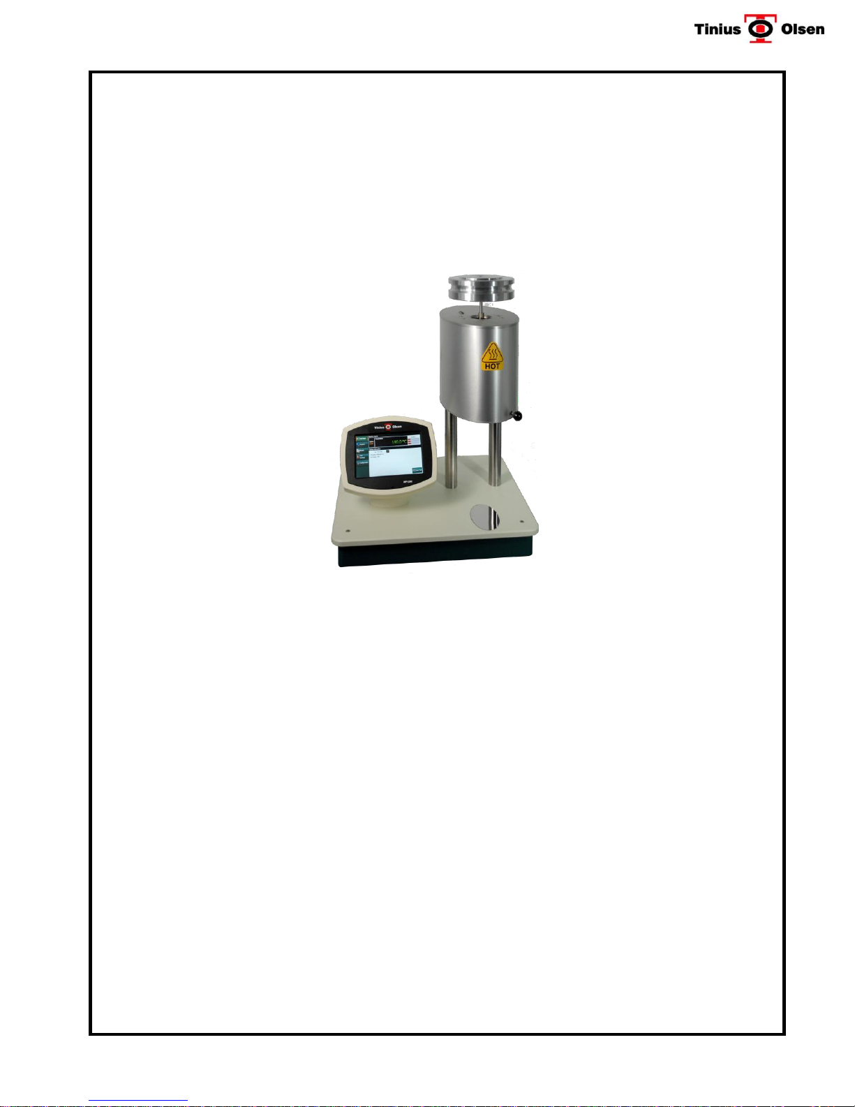
MP1200 & MP1200M
Extrusion Plastometer
(Melt Indexer)
SYSTEM INSTALLATION AND OPERATION MANUAL.
Part #: 02002100 (MP1200) & 02002101(MP1200M)
Revision 2c Date: 8 August 2013
This document contains confidential and proprietary information of Tinius Olsen
Testing Machine Company. In consideration of the receipt of this document, the
recipient agrees not to reproduce, copy, use or transmit this document and/or the
information therein contained, in whole or in part, or to permit such action by others,
for any purpose, except with prior written permission of Tinius Olsen Testing Machine
Company. All rights reserved.
___________________________________________________________________
TINIUS OLSEN TESTING MACHINE COMPANY
Horsham, Pennsylvania 19044-8009 USA
MP1200M shown
1065 Easton Road
www.TiniusOlsen.com


Contents
1 Section 1 – Introduction ....................................................................................................................... 1-1
1.1 Overview .......................................................................................................................... 1-1
1.2 Heavy Duty Construction ................................................................................................. 1-1
1.3 Touch Screen Display ...................................................................................................... 1-1
1.4 Prompt Driven Operation ................................................................................................. 1-2
1.5 Timing .............................................................................................................................. 1-2
1.6 Precision Three Zone Band Heater ................................................................................. 1-2
1.7 Test Results ..................................................................................................................... 1-2
1.8 Communications .............................................................................................................. 1-2
1.9 Options and Accessories ................................................................................................. 1-2
1.10 Machine Dimensions: ....................................................................................................... 1-3
1.11 Electrical Requirements: .................................................................................................. 1-3
2 Section 2 - Model MP1200 Digital Controller/Timer ........................................................................... 2-1
2.1 Introduction ....................................................................................................................... 2-1
2.2 MP1200 Controller/Timer ................................................................................................. 2-1
2.2.1 Touch Screen Keyboard ..................................................................................... 2-1
2.2.2 Machine Display .................................................................................................. 2-1
2.2.3 Navigation Keys .................................................................................................. 2-3
2.3 Three-Zone Temperature Control .................................................................................... 2-4
2.4 Timing Systems ................................................................................................................ 2-4
2.5 Communications Port ....................................................................................................... 2-4
2.6 Multiple Data Determinations (Captures) ......................................................................... 2-4
3 Section 3 –Operating Tools ................................................................................................................. 3-1
4 Section 4 – Available Options & Accessories ..................................................................................... 4-1
4.1 Weights ............................................................................................................................ 4-1
4.2 Glass Reference Thermometers ...................................................................................... 4-1
4.3 Digital Reference Temperature Measurement System (P/N: 02002184) .......................... 4-1
4.4 PPDT Automatic Timing Switch (P/N 02001505) .............................................................. 4-2
4.5 Automatic Timing Switch Calibrator (P/N 02001531) ...................................................... 4-2
4.6 Manual Cutoff Option (P/N: 02002104) ........................................................................... 4-2
4.7 Automatic Cutoff Option (P/N: 02002105) ....................................................................... 4-2
4.8 Weight Support, Lowering and Lifting Device with Swing–Away Weight Support
Platform (WLD) ................................................................................................................ 4-2
4.9 Corrosion Resistant Accessories ..................................................................................... 4-3
4.10 High Melt Flow Plug ......................................................................................................... 4-3
4.11 Go/No-Go Gauge ............................................................................................................. 4-3
4.12 Flow Rate Ratio Attachment Package (P/N 02001418) ................................................... 4-4
4.13 Semi-Automatic Pneumatic Purge ................................................................................... 4-4
4.14 Semi-Automatic Pneumatic Purge & Clean ..................................................................... 4-5
4.15 Horizon Data Acquisition & Machine Control Software .................................................... 4-5
4.16 Orifice (Die) Options......................................................................................................... 4-5
4.17 Piston Rod Options .......................................................................................................... 4-5
4.18 Piston Foot Options.......................................................................................................... 4-6
4.19 Miscellaneous .................................................................................................................. 4-6

5 Section 5 – Set-Up and Installation ..................................................................................................... 5-1
5.1 Unpacking the Machine ................................................................................................... 5-1
5.2 Locating the Machine ....................................................................................................... 5-1
5.3 Leveling the Machine ....................................................................................................... 5-1
5.4 Connections ..................................................................................................................... 5-3
5.5 Updating the Firmware of the MP1200 ............................................................................ 5-5
6 Section 6 - OPTIONAL Programmable Piston Displacement Transducer (PPDT) ........................... 6-1
6.1 Installing the PPDT ordered with the MP1200 .................................................................. 6-1
6.2 Field Installation, Setup and Configuration of the PPDT for encoder type ENCI (for
units that were repaired or not originally purchased with the MP1200). .......................... 6-1
6.3 PPDT Arm Length Adjustment ......................................................................................... 6-2
7 Section 7 – MP1200M Motorized Weight Support and Lowering/Raising Device with Swing-
Away Feature (WLD) ........................................................................................................................... 7-1
7.1 Preparation for use of Factory Installed WLD .................................................................. 7-1
7.2 MP1200M Factory Settings .............................................................................................. 7-1
7.3 DC MOTOR CALIBRATION ............................................................................................ 7-2
7.4 Zeroing the Encoder on the WLD (Synchronize with PPDT) ........................................... 7-3
8 Section 8 – Printer (Optional) .............................................................................................................. 8-1
9 Section 9 – Manual & Automatic Extrudate Cut-Off Tools ................................................................. 9-1
9.1 Tools Required: ................................................................................................................ 9-1
9.2 Installation Instructions .................................................................................................... 9-2
9.3 Operation ......................................................................................................................... 9-3
10 Section 10 – Setup & Operation of the Pneumatic Purge / Purge & Cleaning Attachment on a
Model MP1200 Melt Indexer w/WLD ................................................................................................ 10-1
10.1 Tools Required: .............................................................................................................. 10-1
10.2 Pneumatic Purge/Purge & Clean Attachment Parts List:............................................... 10-2
10.3 Initial Setup Procedures: ................................................................................................ 10-2
10.4 Operation: ...................................................................................................................... 10-5
10.4.1 Manual Operation: ............................................................................................ 10-5
10.4.2 Software Operation ........................................................................................... 10-6
10.5 Operational Notes: ......................................................................................................... 10-7
11 Section 11 – Configuration Mode ...................................................................................................... 11-1
11.1 Machine Settings ............................................................................................................ 11-1
11.2 PID Controls ................................................................................................................... 11-2
11.3 Calibrate ......................................................................................................................... 11-5
11.3.1 Calibrate RTD ................................................................................................... 11-5
11.3.1 Calibrate PPDT ................................................................................................. 11-6
11.3.2 Calibrate WLD ................................................................................................... 11-7
11.4 Diagnostic ...................................................................................................................... 11-8

12 Section 12 – User Settings ................................................................................................................ 12-9
12.1 General Settings. ........................................................................................................... 12-9
12.1.1 Language. ......................................................................................................... 12-9
12.1.2 Printer Selection. ............................................................................................... 12-9
12.1.3 Alarms…………………………………………..…………………………….………12-9
12.1.4 Position. ............................................................................................................ 12-9
12.1.5 Volume. ............................................................................................................. 12-9
12.1.6 Brightness. ........................................................................................................ 12-9
12.2 Calibration Offsets........................................................................................................ 12-10
12.3 Date/Time ..................................................................................................................... 12-11
13 Section 13 – Testing Polymers According to ASTM D 1238 “Procedure A” (Manual Cut-Off
Operation) .......................................................................................................................................... 13-1
13.1 Getting Started ............................................................................................................... 13-1
13.2 Creating a New Procedure A Program .......................................................................... 13-1
13.3 Test Procedure ............................................................................................................... 13-6
14 Section 14 - Testing Polymers According to ASTM D 1238 Procedure B (Automatically Timed
Flow Rate) when the Melt Density is known. .................................................................................... 14-1
14.1 Getting Started ............................................................................................................... 14-1
14.2 Creating a New Procedure B Program .......................................................................... 14-2
14.3 Test Procedure ............................................................................................................... 14-8
15 Section 15 - Testing Polymers According to ASTM D 1238 Procedure B (Automatically Timed
Flow Rate) when the Melt Density is Unknown (Procedure for Calculating the Melt Density of a
Polymer) ............................................................................................................................................. 15-1
15.1 Introduction .................................................................................................................... 15-1
15.2 Creating a New Procedure B Program .......................................................................... 15-2
15.3 Test Procedure ............................................................................................................... 15-7
16 Section 16 - Cleaning Instructions .................................................................................................... 16-1
17 Section 17 - Preventative Maintenance ............................................................................................ 17-1
17.1 Cleanliness ..................................................................................................................... 17-1
17.2 Motorized Weight Lowering Device (MP1200M) ........................................................... 17-1
17.3 Electrical Checks ............................................................................................................ 17-1
18 Section 18 - Calibration/Verification – PPDT Attachment ................................................................ 18-1
18.1 Calibration/Verification Procedure for PPDT ................................................................. 18-1
18.1.1 Introduction ....................................................................................................... 18-1
18.1.2 Theory of Operation .......................................................................................... 18-1
18.1.3 Arm Length Calculation ..................................................................................... 18-3
18.1.4 Height Offset ..................................................................................................... 18-3
18.2 Temperature Verification/Calibration ............................................................................. 18-4
18.2.1 Suggested Equipment ....................................................................................... 18-4

19 Section 19 - Temperature Control Configuration Mode ................................................................... 19-1
19.1 PID Parameters and Tuning -- General ......................................................................... 19-1
19.2 PID temperature control – output terms ......................................................................... 19-1
19.3 PID gains ........................................................................................................................ 19-2
19.4 Recovery Parameters. ................................................................................................... 19-3
19.5 Temperature Controller Status parameters: ................................................................... 19-4
19.6 Automatic Line voltage compensation ........................................................................... 19-4
20 Section 20 - Recommended Spare Parts List .................................................................................. 20-1
21 Section 21 - MP1200 Packing/Shipping Instructions ..................................................................... 21-1
TINIUS OLSEN TESTING MACHINE COMPANY
FACTORY CERTIFICATE
This is to certify that the Tinius Olsen MP1200 Extrusion Plastometer (Melt Indexer) and
Accessories are checked prior to shipment and found to conform to the applicable
portions of ASTM D 1238 and ISO 1133 Test Methods (when used with the appropriate
options).
The verification devices are traceable to the National Institute of Standards and
Technology and are listed below.
The orifices are checked with orifice gauges manufactured and calibrated with
Calibration Standards traceable to the International System of Units (SI) through
NIST.
Piston feet, rods and collars are checked using devices verified with Gage Blocks
traceable to the International System of Units (SI) through NIST.
The weights are calibrated with weights traceable to the International System of
Units (SI) through NIST.
Note: The instrument, and especially components subject to wear during normal use,
should be inspected periodically to insure continued conformance to ASTM D
1238 and ISO 1133.


CAUTIONS
CAUTION: Read the instruction manual thoroughly before attempting to use this
equipment.
CAUTION: This instrument has been designed to determine the melt flow index
property and other thermal processing properties of polymers. It is not intended for any other
use. Any attempt to use this instrument in any fashion other than its intended use may
damage the machine and/or harm the operator.
CAUTION: Do not use a sharp object to press any of the buttons on the Model
MP1200 Controller, as this will damage the LCD screen.
CAUTION: This machine is designed for indoor use only. It shall be used in a
CAUTION: The tools used on the machine may get hot during use.
controlled environment (temperature range 5oC to 40oC, maximum R.H. of 80% at 31oC).
Maximum operating altitude is 3,200 meters. The area that it is located shall be free from
vibrations.
CAUTION: Prior to shipment, the cylinder of the machine is coated with oil to
prevent rust from forming. When the machine is first turned on, it is normal for the machine
to “smoke” as the cylinder comes to temperature and the oil residue burns off. To minimize
the release of smoke, clean the cylinder thoroughly before turning the machine on. Be sure
that a ventilation system is operating at this time.
CAUTION: In some instances an exhaust system may be required to remove the
fumes and/or odors released during a test. These instructions do not address all of the
safety concerns related to ventilation of fumes produced during normal testing operations.
CAUTION: The machine is heavy and care must be used when lifting the
machine from the box or moving the machine. Always lift the machine by the base plate.
DO NOT the machine up by the Motorized Weight Lowering Device (WLD) or by the
furnace assembly.

CAUTION: Do not exceed the flash point of the material being tested.
CAUTION: Possible pinch points associated with the weight-lowering device exist.
One is between the lift cap and the lifter top at the bottom most position of the platform and
the second exists between the weight lowering platform and the piston rod.
CAUTION: The surfaces of the furnace assembly can be extremely hot when the
machine is in operation!
CAUTION: Protective gloves should be worn when operating the machine.
CAUTION: Use caution when working with machines equipped with manual and
automatic extrudate cutters. Wear protective gloves to avoid cuts & burns.
CAUTION: The Motorized Weight Lifting/Lowering Device (WLD) is designed to
apply (and remove) test loads onto the piston. During normal operation a weight support
plate carrying various test loads moves up & down. At its uppermost position, the
mechanism will rotate 90o clockwise to facilitate cleaning of the bore. Ensure that there is
proper clearance for this action at the installation site.
CAUTION: Weight retaining rods must be installed to prevent weights from
falling.
CAUTION: Keep flammable materials from long term contact with the furnace.
CAUTION: Unplug the machine before any attempt to remove covers.

WARRANTY
The Tinius Olsen Testing Machine Company guarantees its products to be free from defects in
material and workmanship under normal use and service for which they were intended, and under
condition of proper maintenance for one year from date of receipt of equipment.
CALIBRATION
Tinius Olsen certifies that this instrument meets all dimensional, temperature control and
performance specifications of ASTM D 1238 and ISO 1133 Parts 1 & 2. That specification
recommends verification of calibration at least once a year. Contact Tinius Olsen’s Field Service
Department at (215) 675-7100 or contact your local Sales & Service Representative to schedule an
appointment.
SERVICE & PARTS SALES
For genuine Tinius Olsen parts and service, contact Tinius Olsen Customer Service
customerservice@tiniusolsen.com.
Thank you for your purchase!
ATTENTION
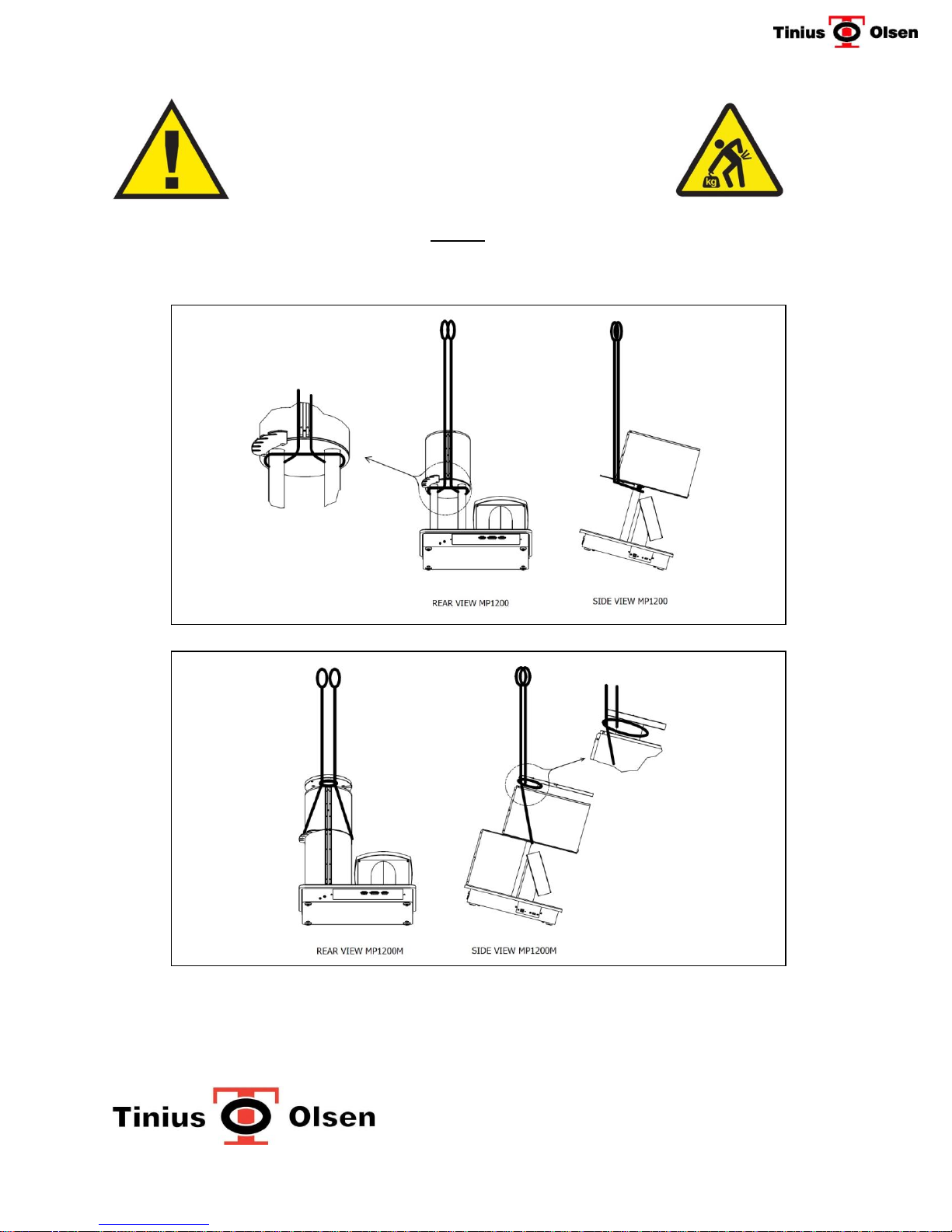
To remove the instrument from the box, use a strap looped around the bottom of the furnace to lift out of
the box as shown in the diagrams below. DO NOT lift by the weight support!! Alternatively, cut down the
sides of the box and lift by the base plate.
Model MP1200 – Net weight 22 kg (47 lbs)
Model MP1200M – Net weight 36 kg (79 lbs)
Install weight retaining rods (on MP1200M models) before use.
Check power requirements before use.
Clean the bore of the furnace prior to use. The machine may emit “smoke“ from the bore as oil coating u sed to
protect the bore from rust during shipping burns off when first turned on..
Please note that the MP1200 was calibrated at the factory prior to shipping. .

1 Section 1 – Introduction
1.1 Overview
The Tinius Olsen MP1200/MP1200M Extrusion Plastometer (Melt Flow Indexer) with
microprocessor-based Model MP1200 Controller/Timer, is used for measuring the flow rates
of thermoplastics. The unit is a dead-weight piston plastometer with which the extrusion rate
of thermoplastic materials through an orifice of specified dimensions is determined under
prescribed conditions of temperature and pressure in accordance with ASTM Standard Test
Method D1238 & ISO 1133-1 & 2. With minor procedural or equipment modifications, the
MP1200 can also meet BS 2782, DIN 53735, JIS K7210 and other similar standards;
including ASTM D2581, D3364, D4203, D4507 and D4550 (a special orifice is required for D
3364). Other methods, such as D2116, D3159, D3275 and D3307, require the optional
corrosion resistant cylinder, orifice and piston foot.
A basic machine (MP1200) may be used for Procedure A - Manual Operation. A weight (s)
will be required to apply the test load. The amount of load is material dependent, so
weights are sold separately. With the addition of optional accessories (PPDT), Procedures
B & C (ASTM D1238 Procedure C) - Automatically Timed Flow Rate Measurement for Melt
Flow Rate (MVR) and/or Melt Volume Rate (MVR) can be performed.
The MP1200M is equipped with a motorized Weight Lifting/Lowering Device (WLD). It can
also be used for Procedures A, B, C & D when equipped with the optional PPDT (Flow Rate
Ratio Attachment is required for Procedure D). A weight(s) will be required to apply the test
load. The amount of load is material dependent, so weights are sold separately.
CAUTION: This instrument has been designed to determine the flow rate and other thermal
processing properties of polymers. It is not intended for any other use. Any attempt to use
this instrument in any fashion other than its intended use may void the warranty, damage the
machine and/or harm the operator.
1.2 Heavy Duty Construction
Sturdy design includes housing for temperature and timing controls, rugged uprights for
supporting the hardened steel test cylinder, which is heated by a precision three zone
controlled band heater, is insulated and jacketed in an aluminum housing. A set of
operating tools, bottom release orifice feature, mirror and a tool rack are included with each
machine. The unit is semi-portable and contains provisions for leveling the cylinder.
1.3 Touch Screen Display
The touch screen display allows the operator to interact with the unit to easily configure test
programs, run tests, and view results. Testing programs can be stored for recall or
necessary values can be entered at test time. Programs can be set up and stored for a
variety of tests.
Tinius Olsen MP1200 Extrusion Plastometer Page 1-1
Operation Manual # 02002215

1.4 Prompt Driven Operation
The selected program prompts the operator to enter the necessary information when
starting a test, alerts the operator to perform tasks that may be necessary during the test,
prompts for any information that might be necessary after the test, and calculates and
displays the test results.
1.5 Timing
Timing functions up to 9999 seconds in 0.01 second increments are available for preheat
timing, cut-off intervals, elapsed test time, piston displacement timing, operating an
automatic weight support and lowering device as well as other optional features. Audible
alarm features are also provided to prompt the operator to perform functions such as apply
load, cut off extrudate, etc.
1.6 Precision Three Zone Band Heater
310 Watts (nominal) -- contains a special concentric heating element, which is form-fitted
and designed to uniformly maintain the required temperature. The heater and furnace
assembly is rated for use up to 450°C. Three platinum RTD Probes sense the cylinder
temperature, sending signals to the MP1200 Controller, which regulates the temperature of
the upper and lower portions of the cylinder to within ± 0.1°C. The temperature of the lower
portion of the cylinder is displayed as the Actual Temperature (AT).
1.7 Test Results
For Procedure A type tests, Flow Rate (Melt Index) is calculated and displayed for each cutoff. When Procedure B type tests are performed using the optional PPDT Automatic Timing
Switch, Flow Rate (MFR), and Volume Rate (MVR) may be determined and Apparent
Shear Stress, Shear Rate and Viscosity, and Volume Rate can be selected for calculation
and display. Melt Density may be entered or calculated from cut-off weight. Average
values are calculated when more than one measurement is made during a test.
1.8 Communications
The test information and results can be sent to an optional printer or the machine can be
interfaced to a computer utilizing the serial communications ports (USB and RS232)
provided as standard. Up to ten machines can be interfaced to a single computer.
1.9 Options and Accessories
A variety of options are available, designed to increase testing efficiency and accuracy.
Tinius Olsen MP1200 Extrusion Plastometer Page 1-2
Operation Manual # 02002215

1.10 Machine Dimensions:
MP1200 - 51 cm (20 inches) wide by 38 cm (15 inches) deep and 58 cm (24 inches) in
height. Net weight approximately 21 kilograms (46 pounds), not including any weights or
options.
MP1200M - 51 cm (20 inches) wide by 38 cm (15 inches) deep and 95 cm (38 inches) in
height. Net weight approximately 32 kilograms (95 pounds), not including any weights or
options.
1.11 Electrical Requirements:
The basic Model MP1200 Extrusion Plastometer is arranged for 115 Volts ±10% or 230
Volts ±10%, 50/60 Hz, Single Phase. Check machine label for actual electrical
requirements.
115 Volt
Input Power.................................................................................................................. 500 W
Voltage ....................................................................................................... 115 VAC +/- 10%
Current ............................................................................................................................ 4.5A
Frequency ................................................................................................................. 50/60HZ
Phase ........................................................................................................................... Single
Line Fuses ........................................................................... Two 5x20 mm slow blow fuses:
Line: 5 A Neutral: 6.3 A
230 Volt
Input Power (Average) ................................................................................................. 500 W
Voltage ......................................................................................................... 230 VAC +/10%
Current ............................................................................................................................ 4.5A
Frequency ................................................................................................................. 50/60HZ
Phase ........................................................................................................................... Single
Line Fuse ................................................................................................. 5A, 250V GDC/213
Note: The MP1200 monitors the incoming line voltage and automatically compensates for small
changes in the line voltage. However, major line voltage problems (spikes, surges,
dropouts) will have to be addressed externally by the user. A qualified electrician should be
consulted and employed should it become necessary to install isolating/regulating
transformers, etc.
The line filter used in the Power Entry Module typically has a leakage current of 0.25 mA to
ground at 115 VAC, and 0.5 mA at 220 VAC. This current leakage may cause a Ground
Fault Interrupt (GFI) receptacle to trip, therefore a GFI is not recommended.
A standard computer grade surge suppressor is recommended for protection.
Tinius Olsen MP1200 Extrusion Plastometer Page 1-3
Operation Manual # 02002215

2 Section 2 - Model MP1200 Digital Controller/Timer
2.1 Introduction
The MP1200 microprocessor-based Controller/Timer is fully interactive with the operator. It
features a LCD touch screen interface; high visibility display; USB port, serial
communications port (RS232); test parameter storage with power-up in last used
parameters; calibration information stored in flash memory; operating controls and other
related features.
2.2 MP1200 Controller/Timer
2.2.1 Touch Screen Keyboard
A touch-screen LCD display is provided for displaying software prompts and tests results.
Also used for entering required numerical test data and for activating specific functions and
features as required. The touch screen keyboard allows the operator to communicate with
the microprocessor in response to interactive prompts, which appear on the LCD display.
Testing parameters can be stored for recall or the necessary values can be entered at test
time. The Parameters can be set up for conducting flow rate tests under both Procedure A
(Manual Cut-off Procedure) and Procedure B (Automatic Timed Procedure). It also can be
used to obtain results for Procedures C & D of ASTM 1238.
CAUTION: Do not use a sharp object on the Model MP1200 Controller, as this
may puncture the touch screen.
2.2.2 Machine Display
2.2.2.1 Status
Indicates the operating condition of MP1200
2.2.2.2 Temperature
Indicates actual temperature of bottom zone of the furnace
2.2.2.3 Piston Height
Indicates the piston (bottom of piston foot) height, when using the PPDT
Automatic Timing switch, relative to the top of the die in the furnace
2.2.2.4 Heater Indicators
Indicators designate top, middle, and bottom heater operation.
Tinius Olsen MP1200 Extrusion Plastometer Page 2-1
Operation Manual # 02002215
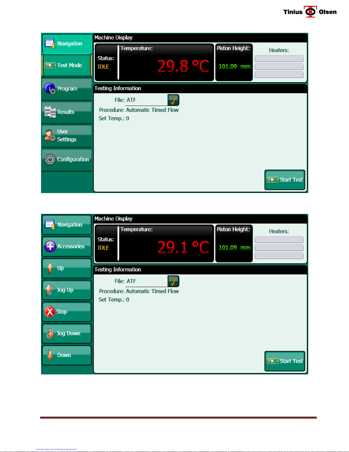
MP1200 Home Screen
MP1200M Home Screen
Tinius Olsen MP1200 Extrusion Plastometer Page 2-2
Operation Manual # 02002215

2.2.3 Navigation Keys
2.2.3.1 Navigation -
Used to access the motorized weight lifting/lowering device (WLD) functions and
purge/purge & clean functions. This key only appears if the WLD or Purge or
Clean functions are turned on in the Configuration Mode.
2.2.3.2 Test Mode
The Test Mode allows the operator to run a test. The operator will have to select
a program from the file list that appears after pressing on the check mark next to
the FILE box. The MP1200 comes from the factory with 7 sample programs
already entered. It is unlikely that any one of these example programs will be an
exact match for the material that is to be tested. They are meant as a starting
point and should be fine tuned the user’s needs. Users may program their own
test before using the Test Mode by using the PROGRAM button on the display
(see instructions below). When properly programmed, the display will indicate
the parameters of the test. The selected program prompts the operator to enter
the necessary information when starting a test, alerts the operator to perform
tasks that may be necessary during the test, prompts for any information that
might be necessary after the test, and then calculates and displays test results.
2.2.3.3 Program
The Program mode allows the operator to select the parameters of the test. The
mode is password protected. The operator can create and store new programs,
select existing programs, edit existing programs or delete programs.
2.2.3.4 Results
The Results mode is used to recall, review and/or print stored test results. For
“Procedure A” type tests, the Flow Rate (Melt Index) is calculated and displayed
for each manual cut-off. When Procedure B type tests are performed using the
optional PPDT Automatic Timing Switch, the Flow Rate (Melt Index), apparent
Shear Stress, Shear Rate and Viscosity, and Volumetric Flow Rate (MVR) can be
selected for calculation and display.
2.2.3.5 User Settings
The User Settings mode allows the operator to select the optional printer, turn
alarms on and off, adjust the volume of alarms, select units, adjust the brightness
of the screen and adjust the Calibration Offsets. The operator can also send logs
to a USB thumb-drive and set the date and time. The mode is password
protected.
2.2.3.6 Configuration
The Configuration mode allows the operator to set the maximum test temperature
and to select which accessories are to be used. It is also used to access the
Calibration and Diagnostics modes. Normally, this information is programmed at
the factory. The mode is password protected.
Tinius Olsen MP1200 Extrusion Plastometer Page 2-3
Operation Manual # 02002215

2.3 Three-Zone Temperature Control
The temperature controller features three-zone proportional, integral, and derivative (PID)
control, assuring spatial temperature variations of less than ± 0.25°C along the test area of
the cylinder. Temperatures up to 450°C are controlled and displayed to ± 0.1°C; utilizing
three platinum RTD’s embedded in the cylinder wall. The controller also has built-in
temperature sensor recognition indicator. If an RTD opens or shorts out (or temperature
control becomes erratic), power to the heater is interrupted and an error message is
displayed.
2.4 Timing Systems
Timing functions up to 999 seconds are available for preheat timing, cut-off intervals,
operating a WLD, as well as other optional features. Piston displacement timing is
displayed in 0.01 second increments up to 1000 seconds and in 0.1 second increments
from 1000 to 3600 seconds. An audible alarm can be activated which will prompt the
operator to perform functions such as applying the load, cutting off the extrudate, etc.
2.5 Communications Port
The test information and results can be sent directly to an optional printer or the machine
can be interfaced to a computer utilizing the serial Communications Ports (USB and EIA-
232) provided as standard. Up to ten machines can be interfaced to a single computer
2.6 Multiple Data Determinations (Captures)
The MP1200, when equipped with the optional PPDT gives the operator the ability to make
up to 10 individual flow rate/volume rate (melt index) determinations within a single sample
charge when performing a test to ASTM Procedure B. While this feature is not required by
ASTM D 1238, it is required for ISO 1133 testing. It can also be useful for checking the
consistency of results and in improving accuracy by isolating sources of error such as air
bubbles and allowing the operator to eliminate obviously flawed data. The multiple capture
features may be used with any material, but it is most often used with materials that have
flow rates greater than 10 g/10 minutes. A typical example of the test parameters used for
a multi-capture test has been preprogrammed in Program #4 (see Table 11-1).
Tinius Olsen MP1200 Extrusion Plastometer Page 2-4
Operation Manual # 02002215

3 Section 3 –Operating Tools
The following tools are included with each MP1200 as standard equipment. Refer to Figure 3-1 for
an illustration. See Section 16 for cleaning instructions.
IMPORTANT: All these tools are made of materials that are softer than the cylinder. This is to
prevent any scoring or damage to the walls of the cylinder. If the cotton cleaning patches
cannot effectively clean the cylinder walls, an optional 0.406” diameter soft brass brush
(available from Tinius Olsen) can be used to help clean the cylinder.
One (1) ASTM Piston Assembly (Items 1A, 1B & 1C, Figure 3-1) - consisting of a
removable stainless steel piston foot (P/N: 02001086); piston guide collar (P/N:
02002149); and ASTM piston rod (P/N: 02002163). The piston rod and foot weighs
100 grams (not including the guide collar). It is considered the first 100 grams of all
test loads.
One (1) Charging Tool (P/N: 02001582), is used to compress the test material down into the
cylinder (cylinder bore), and helps to remove some of the entrapped air when
charging material. Provided with a replaceable tip (P/N: 02001071).
Two (2) ASTM D 1238 Orifice (die), D2 tool steel (P/N: 02001030).
CAUTION: Machines supplied with a nickel-chrome alloy bore should not be used with the
standard tool steel die. Please use either the carbide or satellite die options.
One (1) Level (P/N: 02001271) - used to check the Cylinder Alignment (Level) of the
cylinder. This level is made to fit over the end of the Piston Rod Assembly, with the
piston and orifice in the cylinder.
One (1) Stainless Steel Funnel, (P/N: 02002155) - is used to help introduce a sample of
material into the cylinder.
One (1) Cylinder Cleaning Tool, (P/N: 02001527) is used to clean the cylinder after each
test with the cotton cleaning patches.
One (1) Cutoff Tool, (P/N: 02001090) this U-shaped tool is used to cut-off the extruded
sample at the bottom of the orifice.
One (1) Orifice Drill, (P/N: 02002193) this soft drill bit is used to clean material out of the
inside diameter of the orifice.
CAUTION: The tools used on the machine may get hot during use.
Tinius Olsen MP1200 Extrusion Plastometer Page 3-1
Operation Manual # 02002215
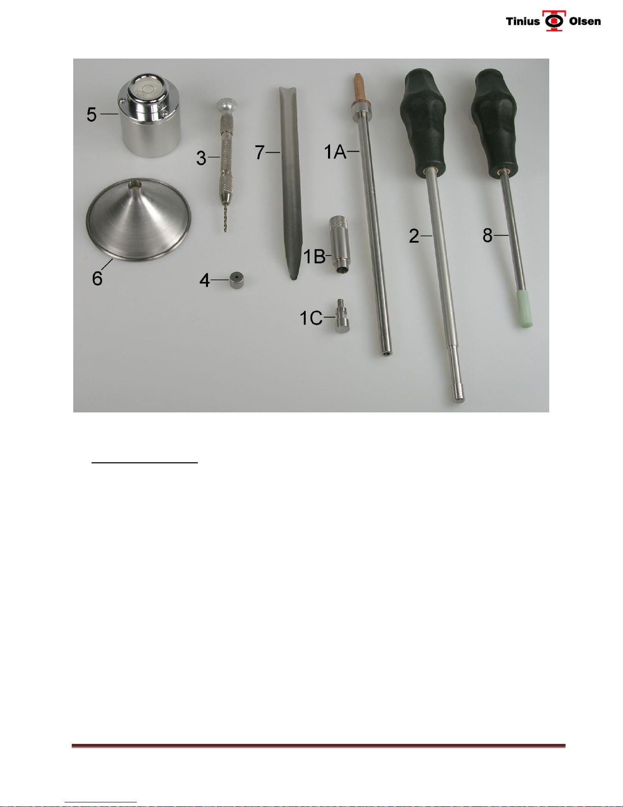
Figure 3-1 – MP1200 Melt Indexer Tools Supplied with Machine
1. Piston Rod Assembly: 4. D2 Tool Steel Orifice (P/N 02001030)
A. Piston Rod (ASTM) (P/N 02002163) 5. Level Assembly (P/N 02001271)
B. Guide Collar (P/N 02002149) 6. Funnel (P/N 02002155)
C. SS Piston Foot (P/N 02001086) 7. Cutoff Tool (P/N 02001090)
2. Cylinder Cleaning Tool (P/N 02001527) 8. Charging Tool (P/N 02001582)
3. Orifice Drill (P/N 02002193)
Tinius Olsen MP1200 Extrusion Plastometer Page 3-2
Operation Manual # 02002215

ASTM D 1238
TEST CONDITION
(Reference Only)
TEST LOAD
(GRAMS)
=
USE WEIGHT(S)
(GRAMS)
+
PISTON
WEIGHT
A, D & K
325
=
225 (P/N 02001176)
+
100
B, C, E, L, R, T, V & W
2,160
=
2,060 (P/N 02001180)
+
100
H & O
1,200
=
1,100 (P/N 02001181)
+
100 I 3,800
=
3,700 (P/N 02001186)
+
100
J & U
12,500
=
2,400 (P/N 02001193) +
10,000 (P/N 02001187) .
+
100
G, P, S & X
5,000
=
4,900 (P/N 02001185)
+
100
F
21,600
=
6,600 (P/N 02001184) +
4,900 (P/N 02001185) +
10,000 (P/N 02001187) .
+
100
M
1,050
=
950 (P/N 02001183)
+
100 N 10,000
=
9,900 (P/N 02001188)
+
100
Q
1,000
=
900 (P/N 02001182)
+
100
4 Section 4 – Available Options & Accessories
4.1 Weights
Table 4-1 shows the weights that can be supplied for the standard test conditions in ASTM D
1238 and ISO 1133. The piston rod and piston foot (less the collar) weigh 100 grams. All the
weights are marked in grams. Tinius Olsen certifies that the weights are accurate to within
+/- 0.5% of the stamped weight.
EXAMPLE: To apply a Test Load of 2.16 kilograms you would use the 2,060 gram weight,
adding in 100 grams for the piston rod assembly (less the collar).
Table 4-1 – Weight Loading for Typical Melt Flow Rate Tests
4.2 Glass Reference Thermometers
Tinius Olsen no longer supplies thermometers. Model TO410 is a digital temperature
measuring system that can be used instead of thermometers.
4.3 Digital Reference Temperature Measurement System (P/N: 02002184)
The Model TO410 handheld, battery operated temperature verification kit is designed for use
with Melt Flow Indexers. This device is for use from 100 to 400 degrees C. It has a
resolution of 0.001 degrees C and an accuracy of approximately 0.05 degrees C. It includes
an RTD with tips designed to properly access the temperature of the bore of a Melt Flow
Indexer. Also included is a dual voltage charger with 4 different power outlet adapters.
Calibration certificates from an ISO 17025 accredited laboratory are provided.
Tinius Olsen MP1200 Extrusion Plastometer Page 4-1
Operation Manual # 02002215

4.4 PPDT Automatic Timing Switch (P/N 02001505)
The PPDT is required when conducting Procedure B - Automatically Timed Flow Rate
Measurement tests in accordance with Procedure B of ASTM D 1238, ISO 1133, DIN 53735,
JIS K7210 and other similar methods. It is also necessary for volume measurements (MVR).
The PPDT utilizes a precision optical encoder to monitor piston position and operate the timer
in the MP1200 Controller/Timer. The Starting Positions and Piston Travel Distances for up to
ten “time vs. distance” captures can be preprogrammed into the MP1200 Controller/ Timer.
4.5 Automatic Timing Switch Calibrator (P/N 02001531)
NOTE: To use the Switch Calibrator with the MP1200, add Adapter Assembly, P/N:
02002195.
Used for verifying and calibrating the actual piston travel distances measured by the PPDT.
It can also be used to verify and/or calibrate older style Mechanical and Programmable
Actuating Switches and Programmable Piston Displacement Transducers used on older
Model UE, MP987, MP993, MP993a and MP600 Extrusion Plastometers. However, the
instructions in this Manual cover only the verification/calibration of the PPDT on a melt
indexer equipped with a MP1200 Controller/Timer. Contact the factory for instructions for
verification/calibration when using other types of controllers and actuating switch types.
The Calibrator consists of a 0 to 2” barrel-type micrometer head with 0.001” divisions, a
threaded spacer and a mounting bracket. The mounting bracket permits checking the switch
while it is mounted on the machine. A wooden storage box is also included.
NOTE: Digital version available (02001651). Contact factory for details.
4.6 Manual Cutoff Option (P/N: 02002104)
This optional accessory is available on both the MP1200 & MP1200M. It can be used to cut
the extrudate instead of using the cutoff tool. The operator turns a hand crank to cut the
material.
4.7 Automatic Cutoff Option (P/N: 02002105)
This optional accessory is available on both the MP1200 & MP1200M. It can be used to
automatically cut the extrudate instead of using the cutoff tool.
4.8 Weight Support, Lowering and Lifting Device with Swing–Away Weight Support
Platform (WLD)
This accessory is included with the MP1200M. It is used to raise and lower the test weight(s). It
includes an integrated encoder that permits display and control of the height of the weight support
platform. It can be operated manually by buttons on the touchscreen. When performing
Procedure B, C & D tests, it can be programmed to automatically move to a selected height at the
Tinius Olsen MP1200 Extrusion Plastometer Page 4-2
Operation Manual # 02002215

start of a test and then lower fully to reapply the load after a selected pre-heat period (Release
Time).
The MP1200M is required for automatic operation and is also recommended whenever high
loads are being used in a test. Weights are contained on the weight support platform that
swings-away automatically when in its raised position for easy cylinder cleaning.
4.9 Corrosion Resistant Accessories
A corrosion cylinder and piston feet are available and are recommended for use with
corrosive materials. Both are made from a Ni/Cr alloy. An orifice made from Stellite 6B is
also available (See 4.16).
P/N: MFI-FNICR – Ni/Cr Furnace Assembly, Complete (New Machine)
P/N: 02002190- Replacement Ni/Cr cylinder
4.10 High Melt Flow Plug
A High Melt Flow Plug is available for use with high flow rate materials. The plug is inserted
into the orifice from the bottom of the furnace prior to charging the cylinder. It will keep
material in the bore until the preheat time expires. At that time, it should be removed. Use
caution when removing the plug. Each plug is supplied with a set of 3 spacers. Choose the
spacer that works best.
P/N: 02001483 – Plug for standard die
P/N: 02001481 – Plug for “half” die
4.11 Go/No-Go Gauge
The Go/No-Go gauge is used to check the inner diameter of the standard ASTM D 1238/ISO
1133 orifice (die) for compliance to the test method requirements.
P/N: 02001134: Go/No-Go Gauge, “Half-Die”, CERTIFIED
P/N: 02001133: Go/No-Go Gauge, ASTM D 1238/ISO1133 orifice - CERTIFIED
P/N: 02001034: Go/No-Go Gauge, standard ASTM D 1238/ISO1133 orifice
NOTE: The certified Go/No-Go gauges are only certified by the gage manufacturer. An ISO
17025 certified gage can be supplied at an additional cost.
Tinius Olsen MP1200 Extrusion Plastometer Page 4-3
Operation Manual # 02002215

4.12 Flow Rate Ratio Attachment Package (P/N 02001418)
Use of this option requires that the MP1200M Extrusion Plastometer is also equipped with the
PPDT Automatic Timing Switch. This package consists of:
a) Load change (lift) pins and extended safety uprights and split collars for weight
containment.
b) Weight change height setting adjuster for setting up typical programs.
c) Available Weight Sets (sold separately):
P/N: 02001658 – 3 Load - I2, I10 & I21 – For MP1200M
- includes 2,060, 7840 and 11600 gram weights
P/N: 02001659 – 3 Load - I2, I10 & I21 – For MP1200M with purge option
- includes 2,060, 7840, 1300 gram weights plus 300 g plug.
P/N: 02001660 – 3 load – I2, I5 & I21
- includes 2,060, 2840 and 16600 gram weights
P/N: 02001661 – 3 Load - I2, I5 & I21 – For MP1200M with purge option
- includes 2,060, 2840 and 11600 gram weights plus 300 g plug.
P/N: 02001662 – 2 Load - I2 & I21 – For MP1200M with purge option
- includes 2,060 and 19140 gram weights plus 300 g plug.
P/N: 02001663 – 3 Load - I2, I6 & I21
- includes 2,060, 3840 and 11500 gram weights
Using the above components, flow rates can be determined under up to three different loads
using the following automated sequence. After charging the test material and lowering the
weights over the top of the piston rod, the operator starts the “Preheat” period. At the end of the
“Preheat” period, the WLD lowers and applies the selected total load. The time for the first
selected piston travel is measured and stored. As the test progresses, the load on the piston is
reduced automatically and, after a selected distance to allow for equilibration of flow, the time
for the selected second piston distance is measured and stored, and a similar sequence can be
selected to obtain a measurement under a third load.
4.13 Semi-Automatic Pneumatic Purge
The Semi-Automatic Pneumatic Purge Attachment can be used only on MP1200M models
equipped with WLD (Weight Lowering Device). The assembly is attached to the WLD and will
allow users to purge the test charge to a predetermined starting point. The operator will charge
the material into the bore and start the test, lowering the WLD weight platform to a
predetermined height (determined by manually programming the MP1200 controller or using
Horizon software). The purge feature is then engaged, applying a downward force on the
weight to purge the material from the bore until the weight is stopped by the weight platform. At
the end of the pre-programmed release time period, the weight platform fully lowers and the
test will continue normally until its conclusion. At the end of the test, the purge feature can be
activated to purge any remaining material from the bore.
P/N: MFI-02002103 - (New Machine)
P/N: 02002103 - (Existing Machine)
Tinius Olsen MP1200 Extrusion Plastometer Page 4-4
Operation Manual # 02002215

4.14 Semi-Automatic Pneumatic Purge & Clean
The Semi-Automatic Pneumatic Purge and Cleaning Assist Attachment can be used only on
MP1200M models equipped with WLD (Weight Lowering Device). The assembly is attached to
the WLD and will allow users to purge the test charge to a predetermined starting point. The
operator will charge the material into the bore and start the test, lowering the WLD weight
platform to a predetermined height (determined by manually programming the MP1200
controller or using Horizon software). The purge feature is then engaged, applying a downward
force on the weight to purge the material from the bore until the weight is stopped by the weight
platform. At the end of the pre-programmed release time period, the weight platform fully
lowers and the test will continue normally until its conclusion. At the end of the test, the purge
feature can be activated to purge any remaining material from the bore. After the WLD is raised
to its top position and swings out of the way, the piston can be removed from the cylinder using
the Piston Extraction Tool (included). After the orifice (die) is removed, a cleaning rod is placed
in position by the technician. Cleaning patches are then placed over the bore and the ram is
activated, helping the operator to clean the bore.
P/N: 02002102 - (New Machine)
P/N: 02002217 - (Existing Machine)
4.15 Horizon Data Acquisition & Machine Control Software
Tinius Olsen’s Horizon Software Packages are available for connecting a single Melt Indexer or
up to ten Melt Indexers to a computer. Consult the factory or your local representative for
complete details.
P/N: 02001672 Software – Horizon MFI Primary Platform
P/N: 21001127 Software - Horizon- Multiple Machine Package
4.16 Orifice (Die) Options
P/N: 02001030 – Orifice, D2 tool steel (ASTM D 1238, ISO 1133)-Standard
P/N: 02001268 – Orifice, Carbide 0.0413” ID x 0.157” L (“Half Die”)
P/N: 02001033 – Orifice, Carbide (PVC, ASTM D3364)
P/N: 02001032 – Orifice, Stainless Steel (PVC, ASTM D3364)
P/N: 02001031 – Orifice, Carbide (ASTM D 1238, ISO 1133)
P/N: 02001167 – Orifice, Stellite 6B (ASTM D 1238, ISO 1133) corrosion resistant
4.17 Piston Rod Options
P/N: 02002163 - ASTM Piston Rod
P/N: 02002164 - ISO (only) Piston Rod
P/N: 02002165 - Combination ASTM/ISO Piston Rod)
P/N: 02002149 – Guide Collar, MP1200
Note: The piston rods listed above are for the MP1200 model only. Piston rods from the
MP600 and older models will not work with the MP1200.
Tinius Olsen MP1200 Extrusion Plastometer Page 4-5
Operation Manual # 02002215

4.18 Piston Foot Options
P/N: 02001086 Piston Foot, stainless steel (standard foot)
P/N: 02001130 Piston Foot, stainless steel, hardened 30-35C
P/N: 02001441 Piston Foot, D2 tool steel hardened 50-55C
P/N: 02001113 Piston Foot, corrosion resistant alloy (for use with corrosion resistant alloy
cylinder)
P/N: 02001171 ISO 1133 piston foot (2011 version)
Note: in 2011 ISO TC61/SC5 approved a new version of ISO1133. A new design for the piston
foot was part of that revision.
4.19 Miscellaneous
P/N: 02001071 Charging Tool Tips
P/N: 02001136 500 Cleaning Patches
Brass Cleaning Brushes:
A. Handle (P/N: 02001144)
B. Brush, MI Cylinder (P/N: 02001143)
C. Brush 0.0825” Orifice(P/N:02001142)
D. Brush 0.0413” Orifice (P/N: 02001146)
Tinius Olsen MP1200 Extrusion Plastometer Page 4-6
Operation Manual # 02002215

5 Section 5 – Set-Up and Installation
NOTE: Instructions in this Section cover basic machine setup. For instruction on installing and
operating optional accessories supplied with the unit, please refer to the appropriate Section of this
manual.
CAUTION: This machine is designed for indoor use only. It shall be used in a controlled
environment (temperature range 5°C to 40°C (40 to 100°F), maximum R.H. of 80% at 31°C).
Maximum operating altitude is 3,200 meters (10,000 feet).
CAUTION: In some instances an exhaust system may be used to remove the excess heat
and/or fumes/odors released during a test. These instructions do not address all of the
safety concerns related to ventilation of fumes produced during normal testing operations.
5.1 Unpacking the Machine
Locate the packing list and carefully uncrate and remove all packing material from around
the machine. Carefully remove the machine from the crate. Check all parts and accessories
against the packing list.
CAUTION: The machine is heavy and care must be used when lifting the machine from the
box or moving the machine. Always lift the machine by the base plate. Never pick the
machine up by the Motorized Weight Lowering Device (WLD) or by the furnace assembly.
It is advisable to retain all packing materials until the machine has been installed and
commissioned.
5.2 Locating the Machine
Place the machine on a sturdy, level surface. Place the machine in an area that is free from
vibrations. Place the tools on the rack on the right hand side of the machine.
The basic machine is shipped fully assembled (the operator has to attach the PPDT if you
ordered one). There is some assembly required for optional accessories.
5.3 Leveling the Machine
Insert the orifice in the cylinder, and then insert the piston assembly. Place the precision
level over the top of the piston. The piston rod must be straight and the base of the level
seated cleanly on the shoulder of the piston. Level the machine using the screw adjustment
feet on the corners of the base plate. Verify that the machine is level by rotating the level
only and then the piston assembly only. At all level positions, no more than half of the
bubble will be outside the circle. Remove the precision level from the piston and store it in a
safe place. Turn the machine ON using the switch on the right side of the machine.
Depending on the model, one of the two main screens will appears.
Tinius Olsen MP1200 Extrusion Plastometer Page 5-1
Operation Manual # 02002215

Main Screen MP1200
Main Screen MP1200M
Tinius Olsen MP1200 Extrusion Plastometer Page 5-2
Operation Manual # 02002215
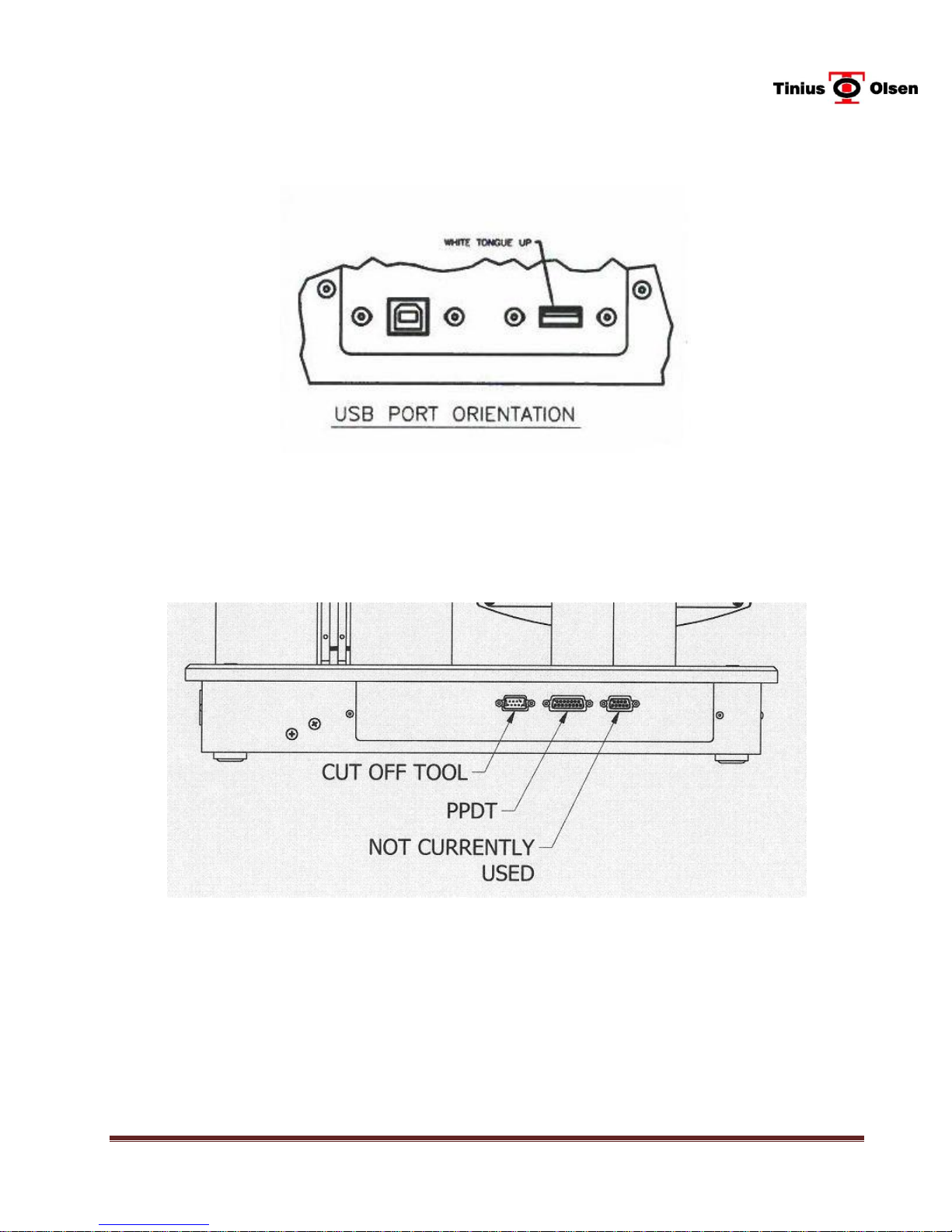
5.4 Connections
Figure 5.4 – 1 – USB Connections on Left Side of MP1200 & MP1200M
Figure 5.4 – 2 - Rear of Standard MP1200 & MP1200M
Tinius Olsen MP1200 Extrusion Plastometer Page 5-3
Operation Manual # 02002215
 Loading...