

Page 1
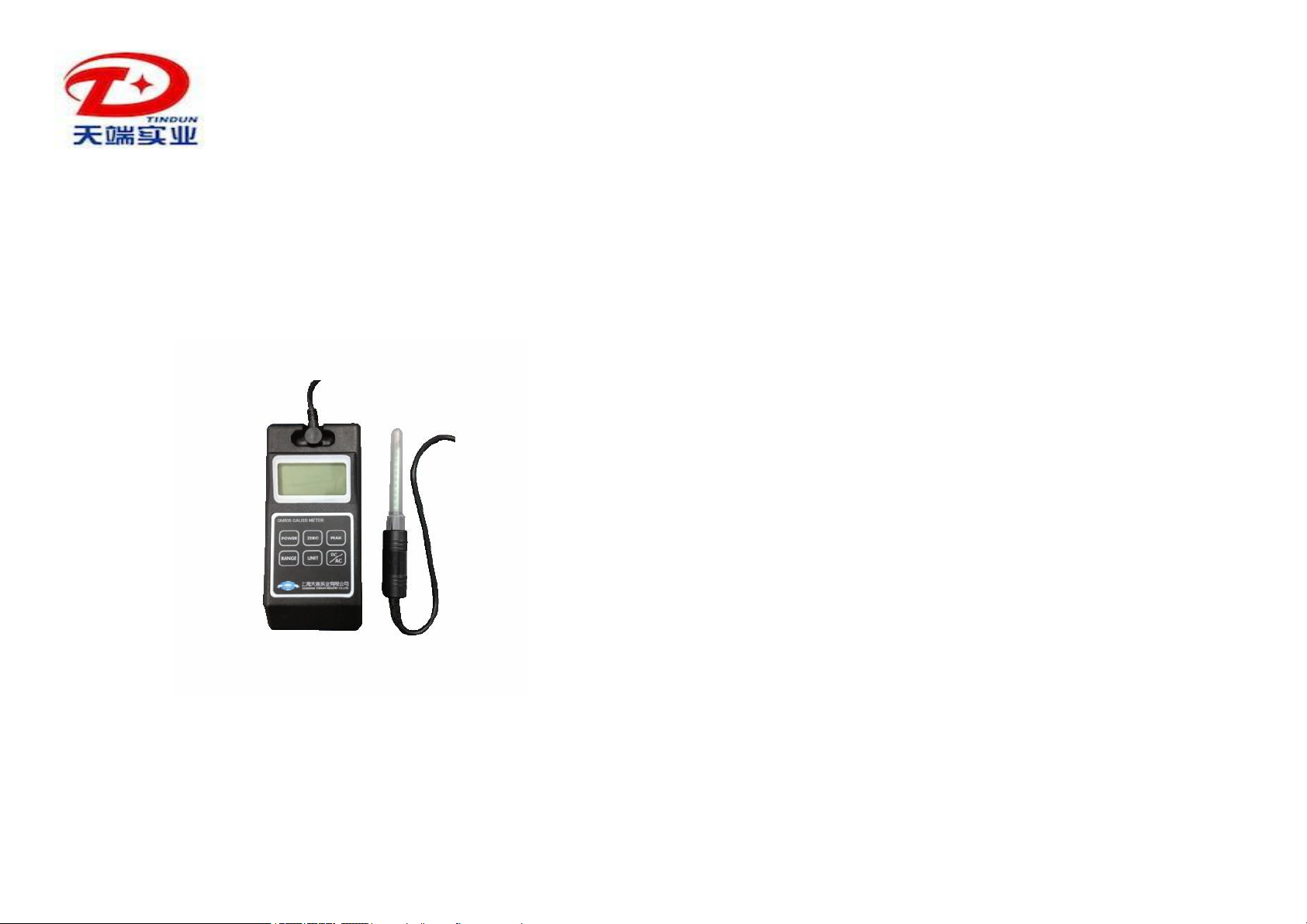
Digital Gauss/Tesla Meter
GM55
User’s Manual
SHANGHAI TINDUN INDUSTRY CO.,LTD
Tel. +0086-21-51873517
Fax: +0086-21-51561516
Email: testmeter@163.com
http://www.testmeter.com.cn
The Gaussmeter GM55 is a new generation of the Gaussmeter GM-2.
It can be used to measure DC/AC magnetic field strength of permanent
magnet materials, motors, speakers, magnetic sensors/ transducer and
other machines and instruments etc. with high resolution.
1) Characteristics
- Wide measuring range and high resolution
- A low-cost measuring device, which is easy to operate, portable
and convenient to handle and store.
- Ideal for quick quality checks and comparative measurements,
with built-in polarity display.
2) Technical Data
Measuring ranges: 0~200mT and 0-2000mT
Basic accuracy: DC: ±2.0%, AC: ±5.0%
Resolution: DC x1: 0.00 ~ 200.00mT, 0.01mT
DC x10: 0.0 ~ 2000.0mT, 0.1mT
AC x1: 0.00 ~ 200.00mT, 0.01mT
AC x10: 0.0 ~ 2000.0mT, 0.1mT
Measuring magnetic field: DC/AC (static & dynamic 10Hz ~ 200Hz)
Functions: Peak hold, Max hold,
automatic range Gs/mT selection
N/S pole display for DC measurement
Automatic probe zero adjustment
Display: 4 ½ LCD
Display Unit: mT/Gs (1mT=10Gs)
Ambient temperature: +5°C ~ +50°C
Storage temperature: -20°C ~ +70°C
Relative humidity: 20% ~ 80%
Power supply: 1.5V AA 4pcs battery
Dimensions: 140mm x 64mm x 30mm
Weight: 300g
3) Accessories
1. +5V DC power supply connecting to 220V AC, 1pc
2. Tansevers Probe, 1pc
1 2
Page 2
3. GMPT-5: transverse probe 1.5x 4 x 40mm, 1pc
4. Adapter,1pc
4) Special probes
GMPA-5: axial probe Ø6 x 40mm
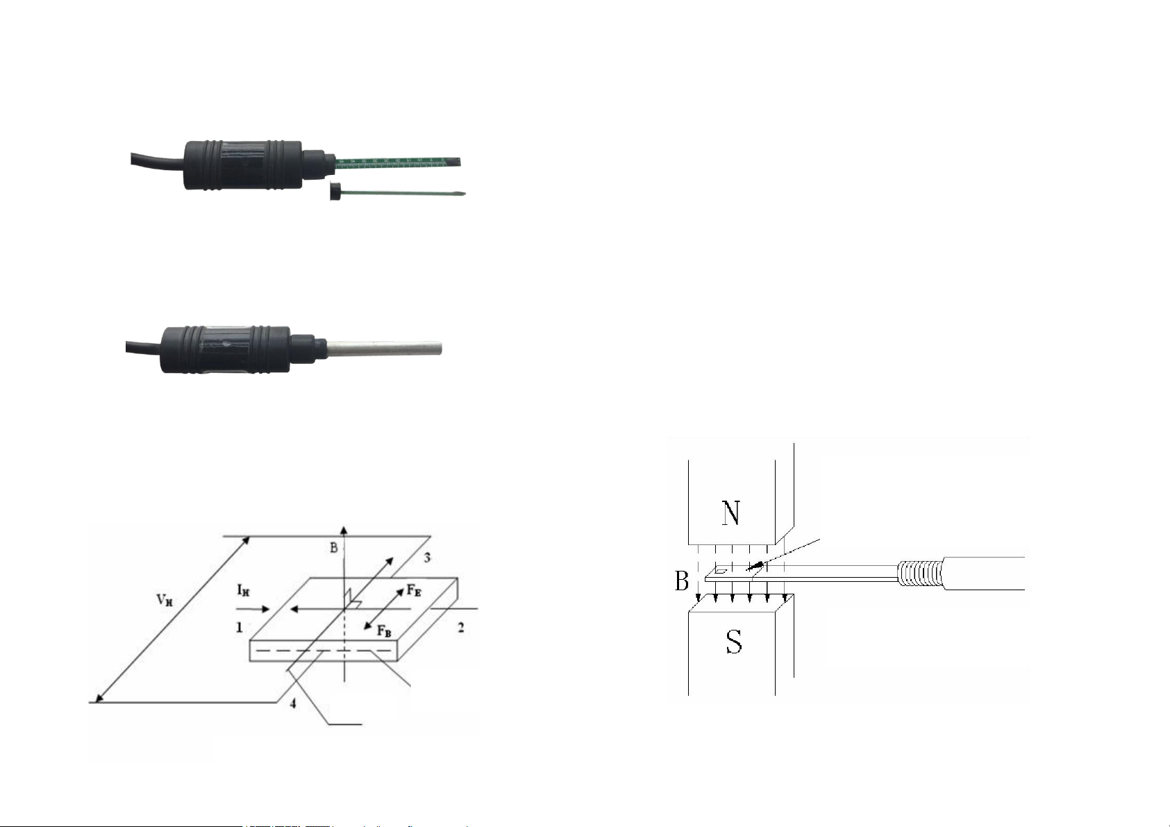
5) Measuring Principle
The Gauss/Tesla meter works with a Hall Effect sensor/probe. There are
two kinds of Hall probes: transverse and axial probes, which are used for
different magnetization directions.
According to the Hall Effect, a voltage can be measured at right angle to
the current path when a conductor or semiconductor with current flowing
in one direction is introduced perpendicular to a magnetic field. The Hall
voltage can be calculated from:
V
H
=
kHIHB
Where: VH: Hall voltage in volts
B: the applied field in Gauss
kH: sensitivity of the element in volts/Gauss
I: bias working current in amperes
The initial use of this discovery was for the classification of chemical
samples. The development of indium arsenide semiconductor compounds
in the 1950's led to the first useful Hall Effect magnetic instruments. Hall
Effect sensors allowed the measurement of DC or static magnetic fields
with requiring motion of the sensor.
6) Measuring Method
The magnetic lines of the measured magnetic field should perpendicularly
pass through the Hall Effect element of the Hall probe.
The sensing plan of the Hall
sensor/probe should be
positioned perpendicular to the
magnetic field
Measurement of magnetic field
in a space or gap
Put the concave side, i.e. the side with a small circle mark of the probe on
the surface of the measured magnet or at the measuring point of a
Electric
Charge
Hall Effect and its Electrical Parameters
3
Vertica
4
Page 3

Incorrect use of Hall probe,
too large measuring force,
Easy damage the Hall probe!!
magnetic field carefully.
Front Panel
Measurement of
surface flux density
of a magnet
Measurement of AC
magnetic field
generated by AC
current
7) Part and Functions
DC Magnetic field
AC Magnetic field
5: Power switch 6: Unit select
AC Mode mark
Peak hold
Pole display (DC)
Measuring value
Display unit
GM55 Digital
Gauss/Tesla Meter
1: Socket-outlet with 4 pins 2: LCD display
3: Peak max/min hold 4: AC/DC Mode
7: Zero/peak reset 8: measuring range
5
6
Page 4

Measuring contact position
Protective tube
Protective tube
Hall sensor/probes
1) Socket-outlet: to connect the Hall sensor/probe to the measuring
2) LCD display: to display the field strength and pole direction (“N”
3) Peak max hold: to display and hold the peak/max value
4) AC/DC Mode: to select the measurement of AC or DC magnetic field
5) Power switch: to switch ON/OFF the measuring instrument
6) Unit select: to select the measuring and display unit
(Gauss or mT)
7) Zero/peak reset: to reset the measuring value and peak mode.
8) Range select: to select the measuring range 0-200mT or
0-2000mT
9) Plug of Hall probe: to connect the Hall probe to the measuring
instrument
10) Measuring circle mark: the side with this mark is the measuring side
of the Hall sensor. You should use this side to measure the surface
magnetic field of permanent magnet. This side should be positioned
perpendicular to the magnetic field
Using this side (without
soldered connection) for
measurement
Don’t use this side (with
soldered connection) for
measurement
Plug of Hall probe
instrument
north pole, “S“ south pole) and ~ AC mode mark etc.
7
Transverse probe
8
Axial probe
Page 5

DC magnetic field
AC magnetic field
0-2000mT
0-200mT
8) Measuring Procedure
1) Install the 1.5V battery to the battery compartment or connect the +5V
power supply to the measuring instrument
2) Connect the Hall sensor/probe to the measuring instrument
3)
Switch on the power of measuring instrument by pressing button (5),
LCD display shows 0.0mT
4) Select measuring range by pressing the button (8), the measuring
range changes between 0-200mT and 0-2000mT as follows:
5) Select AC/DC Mode by using the button (4), the display shows the
following DC or AC measuring mode:
“N” north pole, “S“ south pole for DC magnetic field
6) Select unit by pressing (6), unit changes between Gs and mT
7) Reset Gaussmeter. Keep the Hall probe faraway from magnetic field,
LCD display shows zero after pressing button (7) :
Note: You must reset the Gassmeter before you start a new
measurement after you have changed the measuring range (8) and
AC/DC Mode (4).
8) Select peak hold. You can select peak holding mode or normal
measuring mode by using button (3).
9 10
Unit: mT
Unit: Gs
Page 6

Measuring instrument: 12 months
Hall sensor/probe: no guarantee.
9) Take off the protective tube of the Hall sensor/probe, position the
measuring circle mark (10) on the surface of the measuring object
(such as permanent magnet), and read the display value (measuring
value and pole display “N” or “S“).
Note: the measuring circle mark (10) is measuring point of the Hall
sensor. The pole is N pole if the display is “N” when this mark orients
to the measuring object.
10) Reset peak hold mode. Under the peak holding mode the display
changes only when the actual measuring value is larger than the last
peak value (displayed). Therefore you must reset the peak holding
mode by using button (7) if you need to measure smaller magnetic
field than the peak value. The device works still in peak holding mode
after resetting.
Sample: last peak value: 1500mT, actual peak value 800mT after
reset the peak holding mode
11) After the measurement please put the protective tube on the Hall
probe in order to protect the Hall element and switch off the power
12) The Hall probes delivered are compatible. The measuring accuracy
under using other changed Hall probes is ±2%.
10) Service
Please contact us for technical questions, repairing and
replacement etc:
SHANGHAI TINDUN INDUSTRY CO.,LTD
Tel. +0086-21-51873517
Fax: +0086-21-33321281
Email:sales@imeter.com.cn
http://www.testmeter.com.cn
Normal measuring mode
Peak holding mode
9) Warranty
11
12
 Loading...