

Page 1

NORMAL TRAILER OPERA TION ...................................................................................................................................................................... 3
SAFETY ......................................................................................................................................................................................................4
DECALS & WARNINGS.......................................................................................................................................................................4,5
AIR BRAKE SYSTEM ............................................................................................................................................................................. 6
WHEEL NUT TORQUE ............................................................................................................................................................................ 6
REAR IMP ACT GUARDS ........................................................................................................................................................................6
ABS BRAKING SYSTEM........................................................................................................................................................................ 7
BACKUP WARNING SYSTEM................................................................................................................................................................ 7
CONTROL OF SAFE OPERA TION .......................................................................................................................................................... 8
INSPECTION PROCEDURES BEFORE EACH TRIP ............................................................................................................................................ 9
LEGAL REQUIREMENT FMCS 49 CFR 392.7 ......................................................................................................................................... 9
TRAP DOOR LOCKS.............................................................................................................................................................................. 9
LIGHTS AND REFLECTORS .................................................................................................................................................................10
ELECTRICAL WIRING ........................................................................................................................................................................... 10
FIFTH WHEEL AND KING PIN ENGAGEMENT ......................................................................................................................................10
TIRES .................................................................................................................................................................................................... 10
MUD FLAPS ......................................................................................................................................................................................... 10
TARP SYSTEM ..................................................................................................................................................................................... 10
LANDING GEAR ................................................................................................................................................................................... 10
HUB MAINTENANCE ............................................................................................................................................................................ 11
WHEELS AND RIMS ............................................................................................................................................................................. 11
HUB LUBRICANT ................................................................................................................................................................................. 11
SIDE STRUCTURES .............................................................................................................................................................................. 12
SUSPENSION AND SUSPENSION SUBFRAME .................................................................................................................................... 12
OPERATING INSTRUCTIONS.......................................................................................................................................................................... 13
PARKING/EMERGENCY BRAKING SYSTEM........................................................................................................................................ 13
TRAILER LOADING .............................................................................................................................................................................. 14
TRAILER UNLOADING ......................................................................................................................................................................... 14
TRAP DOOR OPERA TION ....................................................................................................................................................................15
SINGLE SPEED TRAP OPENERS ................................................................................................................................................ 15
2 SPEED TRAP OPENERS........................................................................................................................................................... 15
TRAP DOOR LA TCH (PA WL) - SETUP AND ADJUSTMENT .......................................................................................................16
CONTROL BOX OPERA TION ............................................................................................................................................................... 18
MANUAL OPERA TION ................................................................................................................................................................ 18
SETTINGS FUNCTIONS ON REMOTE.......................................................................................................................................... 18
PROGRAMMING EASY FLOW HOPPER DOORS .......................................................................................................................19
WIRELESS OPERA TION ..............................................................................................................................................................20
TROUBLE SHOOTING GUIDELINES ............................................................................................................................................ 21
PRESSURE RELIEF ADJUSTMENT .............................................................................................................................................. 20
EMERGENCY APPLICATION WITH DRILL ...................................................................................................................................23
ROLL T ARP .......................................................................................................................................................................................... 24
TARP TENSION .....................................................................................................................................................................................24
THUNDER ELECTRIC T ARP SYSTEM ...................................................................................................................................................26
OPTIONAL ARM ADJUSTMENT .................................................................................................................................................. 27
ERROR CODES ........................................................................................................................................................................... 28
SETTING FUNCTIONS ON REMOTE ............................................................................................................................................ 29
THUNDER T ARP RF PROGRAMMING ......................................................................................................................................... 30
THUNDER ELECTRIC T ARP SCHEMATIC .................................................................................................................................... 31
LANDING LEGS ................................................................................................................................................................................... 32
ACCESS SYSTEM ............................................................................................................................................................................... 33
LIFTABLE, REGULA TED AXLE ............................................................................................................................................................. 33
GENERAL MAINTENANCE .............................................................................................................................................................................34
AVOIDING CONT AMINA TION ............................................................................................................................................................... 34
TRAILER WASHING ............................................................................................................................................................................. 34
CORROSIVE DETERIORATION............................................................................................................................................................. 34
TRAP FRAME MAINTENANCE ............................................................................................................................................................. 35
ROLLER DOOR FIELD ADJUSTMENT ............................................................................................................................................36, 37
AIR HAMMER (VIBRAT OR) MAINTENANCE ........................................................................................................................................38
VIBRAT OR AIRLINE SCHEMATIC .........................................................................................................................................................39
HUB MAINTENANCE ............................................................................................................................................................................ 40
WHEEL BEARING INSPECTION ............................................................................................................................................................ 40
WHEEL BEARING ADJUSTMENT ......................................................................................................................................................... 40
BEARING LUBRICANT ......................................................................................................................................................................... 40
BRAKES ...............................................................................................................................................................................................41
AIR BRAKE SYSTEM - TROUBLESHOOTING ............................................................................................................................................... 43
BRAKE CONTROLS ............................................................................................................................................................................. 43
IN-LINE AIR FILTER ...............................................................................................................................................................................44
AIR SYSTEM COLD WEATHER OPERA TION ....................................................................................................................................... 44
AIR BRAKE PIPING SCHEMATIC ....................................................................................................................................................45, 46
SPRING BRAKES .................................................................................................................................................................................47
AUTOMA TIC SLACK ADJUSTERS....................................................................................................................................................... 47
WHEEL ASSEMBLIES...........................................................................................................................................................................48
WHEEL INST ALLATION........................................................................................................................................................................ 48
TIRE CHANGE PROCEDURE .......................................................................................................................................................................... 49
AXLE ALIGNMENT ............................................................................................................................................................................... 50
AIR-RIDE SUSPENSION SYSTEMS ......................................................................................................................................................51
AIR-RIDE SUSPENSION SCHEMATIC ................................................................................................................................................... 52
SPRING SUSPENSION MAINTENANCE ................................................................................................................................................53
ELECTRICAL SYSTEM MAINTENANCE ............................................................................................................................................... 55
LIFT BOX 4-WA Y WIRING SCHEMA TIC ...............................................................................................................................................56
ELECTRICAL SYSTEM DIAGRAM........................................................................................................................................... 57, 58, 59
LANDING LEGS ................................................................................................................................................................................... 60
REPORTING SAFETY DEFECTS - 49CFR 575.6 (a)(2)(ii) ................................................................................................................... 61
MAINTENANCE SCHEDULE - HOPPER .......................................................................................................................................................... 61
TIMPTE “PEACE OF MIND” LIMITED WARRANTY .......................................................................................................................................... 64
FILING A WARRANTY CLAIM ........................................................................................................................................................................ 68
TABLE OF CONTENTS
1
Date of Origin – 02/01/08
Page 2

IMPORTANT
This manual has been prepared to help you operate your new T impte trailer successfully, economically , and safely . Please read your Operator’s Manual carefully and have a full understanding prior
to using your trailer or performing any maintenance. We urge you to contact your T impte T railer
Company factory representative or the Vice President of Engineering at Timpte (402-367-3056)
immediately should you have any questions or need an explanation.
Timpte has provided several warnings in your Operator’s Manual and on your trailer to help prevent personal injury . T impte can not foresee all use or misuse of the trailer. Always use common
sense judgment while using or performing maintenance to your trailer. Your safety is our primary
concern.
This safety alert symbol is used throughout this manual to indicate potential personal
!
Safety decals appear at various locations on your new Bulk Commodity trailer. The decals are
provided for
damaged, painted over, or otherwise difficult to read. Replacement decals are available at no
cost through Timpte by calling 402-367-3056.
safety hazards. Failure to heed the warnings associated with the safety alert symbol can
result in property damage, serious injury or death.
your safety and should be kept clean. Replace any decal that has become worn or
Information contained in this Operator’s Manual is based on the latest information available at the
time of publication. Changes are continually being made to improve our product lines.
In addition to this Operator’s Manual, there is a set of informational manuals supplied with your
trailer from the manufacturers of the various components used to build this trailer including but not
limited to;
• the suspension
• the anti-lock brake system
• the axles, brakes, wheel ends
• the tarp system
• the spring brakes chambers
Please read these manuals carefully as they contain detailed information on these different trailer
components as well as safety and maintenance information that is important to you.
We want to thank you for purchasing a T impte trailer and to let you know that it was designed to
meet your specific needs for a Bulk Commodity trailer and was built for long life and low cost of
operation. However , regular and proper maintenance of the trailer and your common sense use of
it are required to extend the life of the trailer .
Date of Origin – 02/01/08
2
Page 3

NORMAL TRAILER OPERATION
This Timpte trailer is designed for operation within legal highway speed limit s on reasonable road
surfaces for the type of service it was built to perform, in accordance with the noted weight restrictions.
“Normal Service” means the loading and transportation of uniformly distributed legal loads of
properly secured, noncorrosive cargo, in accordance with any applicable factory instructions and
in a manner which does not subject the trailer or parts of the trailer to (a) concentrated loads; (b)
loads in excess of the Gross Axle W eight Rating (GAWR) or Gross V ehicle Weight Rating
(GVWR) stated on the Certification Plate affixed to the trailer by T impte; and (c) accidental damage, or (d) stresses, impacts or shocks greater than those commensurate with normal, reasonable lawful use.
The GAWR (gross axle weight rating) is the structural capability of the lowest rated member of the
running gear components: suspension system, hubs, brake drums, wheels, bearings, axles, brake
linings or tires.
The GVWR (gross vehicle weight rating) is the structural capability of the trailer when supported by
the kingpin and axles with the load uniformly distributed throughout the cargo space.
NOTICE:
The maximum load indicated on the identification plate
may not be a legal load on the highway you plan to use.
States have differing laws and regulations affecting vehicle
lengths and weights on roads that are not a part of the
primary interstate road system.
Modification of the Trailer – Any modification made to the trailer must comply with DOT and
NHTSA regulations and must not compromise the gross vehicle weight rating (GVWR) of the
trailer. Any modification made to the trailer without prior approval of T impte may void the warranty .
Any operation of the trailer outside the limitations stated in this manual will void any responsibility
of Timpte Trailer Company for any of its result s.
3
Date of Origin – 02/01/08
Page 4
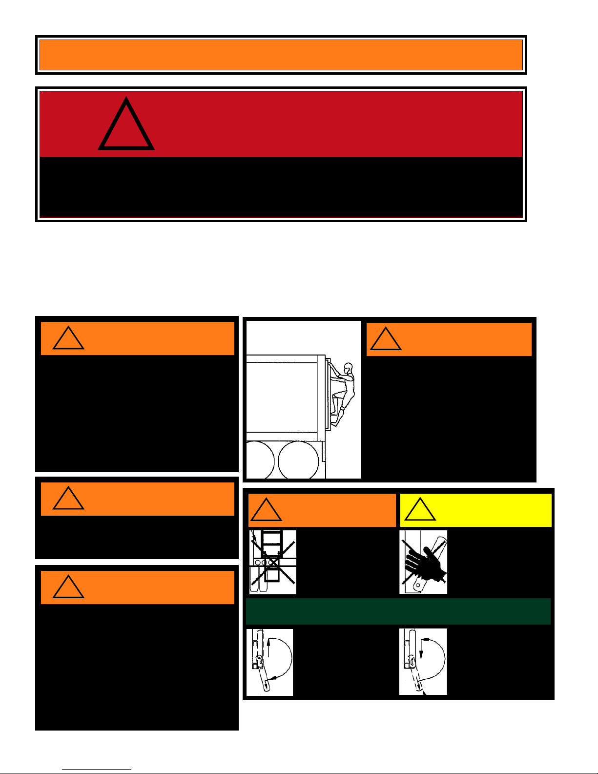
SAFETY
!
WARNING
PERSONAL INJURY, DEATH, AND PROPERTY DAMAGE MAY RESULT FROM
IMPROPER OPERA TION OR UNSAFE PRACTICES. BE SURE T O READ AND
FOLLOW ALL DECALS AND EMBLEMS CAREFULLY .
The following section contains the decals and emblems used on the Timpte Hopper
Trailers. Due to differences in configurations and equipment, your trailer may or may not
use all the decals and emblems shown. Newer trailers may also have decals and emblems that differ from older trailers. Replace damaged or missing decals promptly.
Replacement decals for this trailer are available without charge by calling Timpte Trailer
Company at 402-367-3056.
!
1. CHECK PIN TO ASSURE THAT IT IS PR OPERLY
ENGAGED WITH FIFTH WHEEL.
2. KEEP THE UPPER COUPLER LUBRICATED AND FREE
OF DEBRIS T O PREVENT GALLING OF THE FIFTH
WILL PLA TE.
3. INSPECT THE KING PIN AND THE PLATE ASSEMBLY
REGULARLY FOR WEAR AND CRACKS.
FAILURE TO FOLLOW THESE W ARNINGS COULD RESUL T
IN SERIOUS INJURY OR DEATH.
WARNING
TIMPTE INC
CAUTION
!
WARNING
1. EXERCISE EXTREME CAUTION WHILE CLIMBING
ON ACCESS SYSTEM.
2. ALW AYS MAINTAIN 3-POINT CONT ACT.
(2 HANDS & 1 FOOT OR 2 FEET AND 1 HAND)
3. DO NOT WEAR RINGS OR ANYTHING THAT
CAN CATCH ON LADDER.
4. USE LADDER SIDE RAIL FOR HAND HOLD, NEVER
USE THE RUNG.
5. NEVER CLIMB OVER THE TOP OF THE TRAILER.
NEVER ENTER THE INSIDE COMPARTMENTS FOR
ANY REASON.
FAILURE TO FOLLOW THESE W ARNINGS COULD
RESULT IN SERIOUS INJURY OR DEATH.
!
FAILURE T O USE PROPERL Y MA TCHED WHEELS, STUDS, BRAKE
DRUMS OR CAP NUTS WILL RESULT IN EQUIPMENT DAMA GE
AND COULD RESUL T IN SERIOUS INJURY OR DEATH IF WHEEL
COMES OFF.
!
THIS TRAILER IS EQUIPPED WITH A REGULATED LIFT
AXLE.
* LIFT AXLE MUST BE ACTIV A TED IN DOWN POSITION
WHEN TRAILER IS LOADED . FAILURE TO COMPLY
WILL RESUL T IN DETERIORA TION OF BRAKING
PERFORMANCE AND REDUCED ROLL ST ABILITY .
* LIFT AXLE MUST BE ACTIV A TED IN RAISED POSITION
WHEN TRAILER IS EMPTY.
FAILURE T O FOLLOW THESE WARNINGS COULD
RESULT IN PERSONAL INJUR Y OR DEA TH.
Date of Origin – 02/01/08
WARNING
WARNING
!
WARNING
• FEDERALL Y REQ UIRED LAMPS
MUST NOT BE OBSTR UCTED
• ALW AYS RAISE AND STORE
LOWER LADDER SECTION
BEFORE MOVING TRAILER.
• FAILURE T O COMPL Y CAN
CAUSE INJUR Y OR DEATH.
!
CAUTION
• MOVING PARTS HA VE
PINCH POINTS.
• ST AY CLEAR OF SIDE
RAILS WHEN OPERATING
SWING-DOWN LADDER.
• FAILURE T O COMPLY CAN
CAUSE INJURY.
SWING-DOWN LADDER OPERATION
TO LOWER AND USE LADDER:
1. GRASP RUNG FIRMLY & LIFT.
2. ROTATE LADDER DOWNW ARD.
3. MAKE SURE LADDER IS
SECURELY ENGAGED IN
UPPER ENDS OF SLOTS.
4
TO RAISE AND STORE LADDER:
1. GRASP RUNG FIRMLY, ROTATE
LADDER UPWARD WHILE
HOLDING RADIALL Y OUTWARD.
2. SLIDE DOWNWARD IN SLOTS.
3. MAKE SURE LADDER IS FULLY
ENGAGED (STORED SECURELY).
Page 5

!
THIS TRAILER IS EQUIPPED WITH TRAILING BEAM AIR
1. MANUALLY EXHAUST ALL AIR IN THE SUSPENSION
SYSTEM PRIOR TO SUPPORTING A LOADED TRAILER
ON THE SUPPORT LEGS. FAILURE TO COMPLY CAN
CAUSE STRUCTURAL DAMAGE TO THE SUPPORT LEG
BRACES.
2. DO NOT USE EXCESSIVE FORCE WHEN COUPLING THE
TRACTOR TO THE TRAILER (EMPTY OR LOADED)
CONTINUING TO BACK-UP A TRACTOR/TRAILER WITH
THE TRAILER BRAKES LOCKED CAN ROTATE THE
TRAILING BEAMS AND OVEREXTEND THE SUSPENSION. OVEREXTENSION WILL CAUSE DAMAGE TO THE
SUSPENSION SYSTEM.
3. MANUALLY EXHAUST ALL AIR IN THE SUSPENSION
SYSTEM PRIOR TO AND DURING UNLOADING THE
TRAILER. AFTER UNLOADING THE TRAILER, IMMEDIATELY ACTUATE THE AIR AND WAIT FOR THE SUSPENSION TO RETURN TO THE NORMAL RIDE HEIGHT
BEFORE MOVING THE VEHICLE.
!
WARNING
RIDE SUSPENSION.
WARNING
– DO NOT ATTEMPT TO WALK ON
TOP RAILS, THEY ARE NOT AN
APPROVED WALKWAY
– FAILURE TO COMPLY CAN CAUSE
SERIOUS INJURY OR DEATH
!
IF SPRING BRAKES ARE CAGED , DEACTIVATED OR REMOVED,
THIS VEHICLE WILL HAVE NO EMERGENCY P ARKING BRAKES AND
MUST NOT BE PARKED WITHOUT BLOCKING WHEELS OR DRIVEN.
NEVER STAND BETWEEN THE BACK OF THE TRAILER AND ANY
ST ATIONARY OBJECT.
FAILURE TO FOLLOW THIS SAFETY PRECAUTION WILL RESULT IN
THIS PRODUCT IS PROTECTED BY
US & FOREIGN P ATENTS AND TRADEMARKS INCLUDING:
PATENT # 6,736,297 B2
REGISTRATION # 1,411,224
THIS TRAILER IS EQUIPPED WITH ANTILOCK BRAKE SYSTEM (ABS).
D.O.T. REGULATION FMVSS-121 REQUIRE ABS RECEIVE CONSTANT
POWER FROM THE CENTER AUXILIARY PIN ON THE 7-WAY CONNECTOR.
INSPECT YOUR TRACTOR! TRACTOR MUST SUPPLY CONTANT POWER
FOR THE ABS ON THE CENTER AUXILIARY PIN WHEN THE KEY SWITCH
IS ON. DEACTIVATE ANY SWITCH IN THE TRACTOR THAT WILL TURN THE
AUXILIARY POWER OFF (MUST SUPPLY CONSTANT POWER).
DO NOT MODIFY THE TRAILER ELECTRICAL SYSTEM TO POWER
OPTIONAL EQUIPMENT OFF THE AUXILIARY CIRCUIT. FEDERAL LAW
MANDATES THIS CIRCUIT IS DEDICATED FOR ABS ONLY.
CONTACT TIMPTE ENGINEERING IF YOU HAVE ANY QUESTIONS ABOUT
YOUR PRESENT WIRING OR HOW TO REWIRE FOR AUXILIARY EQUIPMENT.
FAILURE TO FOLLOW THESE WARNINGS COULD RESULT IN SERIOUS
INJURY OR DEATH.
DANGER
DEA TH OR SERIOUS INJURY
6,059,372
6,814,532 B1
2,255,368
TIMPTE TRAILER CO.
1827 INDUSTRIAL DRIVE
DAVID CITY, NE 68632
!
WARNING
WARNING
USE KNOCK RAILS TO DISLODGE COMMODITY,
POUNDING ON SLOPE SHEETS VOIDS WARRANTY.
!
NEVER CLIMB INSIDE THE HOPPER COMPARTMENT!
FAILURE TO FOLLOW THIS WARNING COULD RESULT IN
SERIOUS INJURY OR DEATH.
!
CHECK WHEEL NUTS AFTER INITIAL 50 TO 100 MILES OF
SERVICE. SEE OWNERS MANUAL FOR CORRECT TORQUE
REQUIREMENTS. FAILURE TO FOLLOW THIS WARNING
COULD RESULT IN SERIOUS INJURY OR DEATH.
WARNING
WARNING
P/N 035-03082
!
CAUTION
NEW FMVSS-121 REGULA TIONS MAND ATE HIGHER
PRESSURE LEVELS IN THE SUPPLY LINE.
TRAILER BRAKE PERFORMANCE WILL BE
IMP AIRED IF TRACT OR COMPRESSOR
ADJUSTMENT IS TOO LO W .
CHECK YOUR TRACTOR!
COMPRESSOR CUT-IN PRESSURE, ADJUST TO 105
COMPRESSOR CUT-OUT PRESSURE: RECOMMENDED
AIR BRAKE SYSTEM IS
PSI CUT -IN GO VERNOR
MORE THAN 120 PSI CUT-OUT GOVERNOR
NOTE: THE USE OF ADDITIVES IN THE
NOT RECOMMENDED.
P/N 035-29182
5
CAUTION
DO NOT ATTEMPT
TO HOIST TRAILER
AT THIS FRAME
STRUCTURE.
Date of Origin – 02/01/08
P/N 035-27163
Page 6
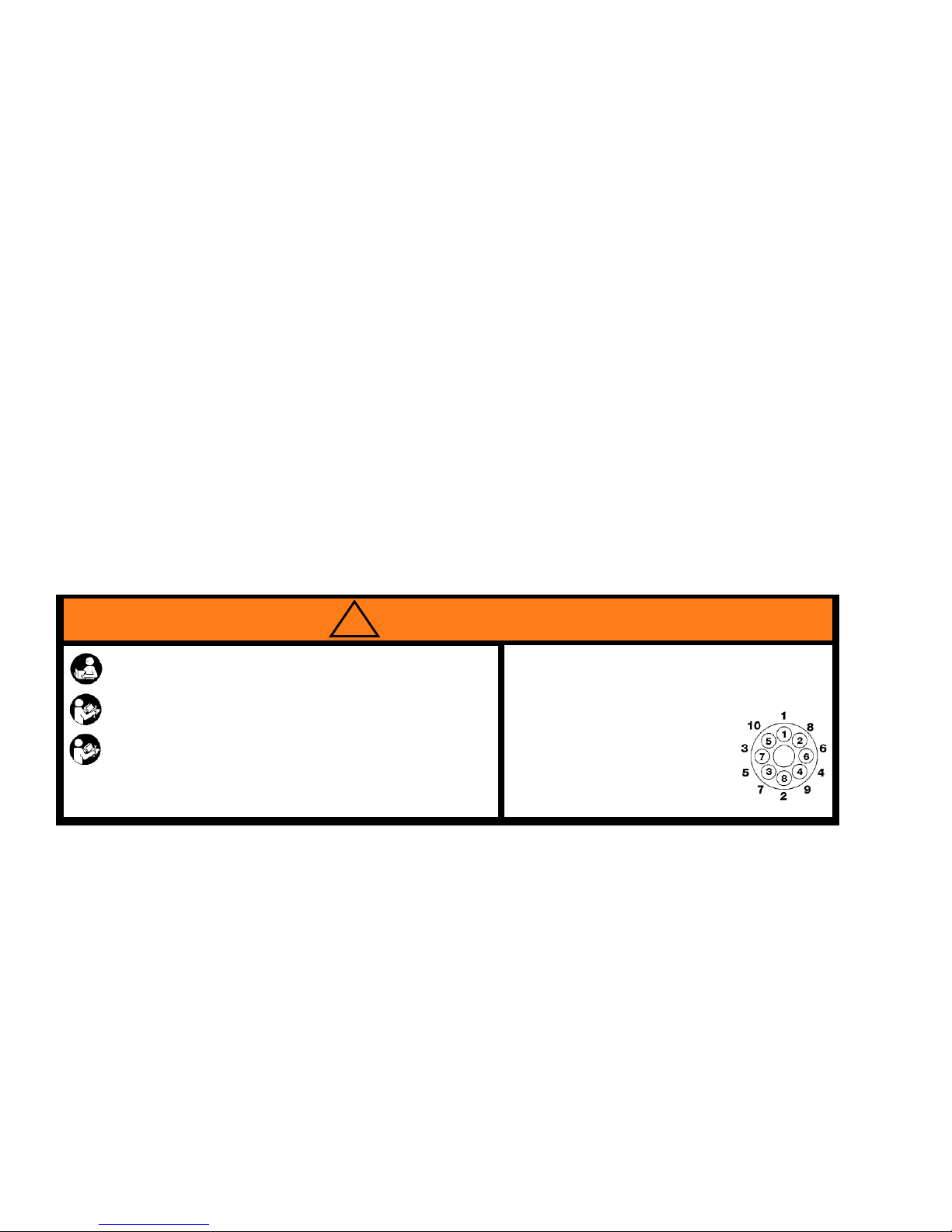
AIR BRAKE SYSTEM
Your new Timpte trailer is equipped with an air brake system which meet s or exceeds the requirements of the federal regulation FMVSS-121 for grade-holding ability and emergency stopping in
the event of an air supply failure in the service brake system. Air pressure is required to release
the parking/emergency brake. As of 10/8/92-FMVSS 121 requires that the supply line for the air
brake system be protected to 70 psi. This pressure level requires that supply line pressure levels
are achieved before the pressure protection valve opens (opening pressure must be higher than
the closing pressure by design).
Keeping your compressor cut-in pressure at maximum levels (over 100 psi) is a clear advantage
for peak operation of your entire system, we recommend using a 105 psi cut-in governor setting.
Governor cut-out pressure should be at 120 psi minimum. Low compressor cut-in pressure may
result in poor performance of the system, for example slow parking brake release time.
Should you still have a problem with your brake system after working through all of the inspection
items and tests listed in this manual’s maintenance section or in the brake manufacturer’s manual
supplied with the trailer , contact your T impte factory representative.
WHEEL NUT TORQUE
Proper torquing and retorquing the wheel nuts are critical to prevent the loss of wheel equipment.
Wheel nuts should be torqued to 450 to 500 ft. lbs. (dry). Refer to the manufacturer’s decal on the
side of the trailer or manufacturer’s maintenance information supplied with the trailer for proper
torque specifications and tightening sequence.
Wheels must be checked and retorqued after the first 50 to 100 miles of use. This is important
every time you change a wheel. Check the fastener torque on a regular on-going basis.
!
WARNING
1. Read and understand this warning and the installation, Service and Safety Instruction Manual to understand
all safety precautions, proper operation, and maintenance of your Webb hub. Failure to do so could result in
death or serious injury and could result in a compromise of your vehicle’s safe operation through loss or failure
of a wheel or the compromise of the braking system. Copies of the installation, Service and Safety Instruction
Manual are available, free of charge, from Webb Products, Inc., upon request.
2. Always use a properly installed calibrated torque wrench to assure proper torque. Under torque and over
torque can cause thread and/or nut damage and could result in the loss of a wheel. Failure to ensure proper
torque could result in death or serious injury and could shorten the expected life of this product.
3. Recheck torque after the first 50 to 100 miles of service. Parts may seat naturally, causing the torque to drop.
A drop in torque could result in the loss of a wheel. Proper torque is essential to avoid damage or compromise
of your vehicles safety. Failure to ensure proper torque could result in death or serious injury.
2310 INDUSTRIAL DRIVE, S.W.
CULLMAN, ALABAMA 35055
256-739-6660 WWW.WEBBWHEEL.COM
(FOR PILOT MOUNTED DISC WHEELS)
APPLIES TO M22 X 1.5 STUDS / TWO PIECE FLANGE NUT.
All threads are right hand metric.
Tighten Flange Nuts to 50 ft.lb. using sequence
shown.
Check Disc-Wheels for proper positioning on pads
and proper seating against flange.
Tighten Flange Nuts to recommended torque using
sequence shown.
RECOMMENDED TORQUE: 450 - 500 FT. LBS.
HUBS
8 - 10 STUD HUBS
REAR IMP ACT GUARDS
As of 1/26/98, all trailers must comply with FMVSS 223 and 224, which specify equipment and
performance standards for rear impact guards on new semi-trailers. If required by this statute, a
RIG (rear impact guard) has been installed on your trailer that has been designed to resist specified forces and absorb energy at a specific rate in the event of a rear collision with the trailer per
the standard. T railer RIG’s are subject to impacts and stress in docking and loading operations.
It is therefore important that you inspect them regularly for signs of damage or wear . Failure to
follow this warning could result in serious injury or death.
Date of Origin – 02/01/08
6
Page 7

!
A DAMAGED REAR IMPACT GUARD MAY NOT BE AS STR ONG AS THE ORIGINALLY MANUFACTURED GUARD AND MAY NOT SATISFY THE PERFORMANCE
STANDARDS OF FMVSS 223 AND 224. ALTERATIONS OR REPAIRS TO THE RIG
COULD HA VE THE SAME EFFECT. PRIOR TO REPAIRING OR MODIFYING ANY
TIMPTE RIG, CONTACT THE VICE PRESIDENT OF ENGINEERING AT TIMPTE AT
402-367-3056. FAILURE TO FOLLOW THIS WARNING COULD RESULT
WARNING
IN SERIOUS INJURY OR DEATH.
Pre-trip inspections should be made of the guard to assure its integrity and strength. Broken
welds, bent components, or other damage will likely affect its performance.
For these reasons, RIG inspection, service and repair records should be maintained. Repairs
and replacements must be in accordance with the original design specifications of the guard. Any
questions regarding repair or replacement should be directed to the Vice President of Engineering at Timpte.
ABS BRAKING SYSTEM
As of 3/1/98 all trailers manufactured with air braking systems are required to have an ABS (AntiLock Braking System).
The system used on your trailer meets or exceeds the FMVSS 121 requirement for ABS. The
ABS system on your Bulk Commodity trailer is a 4S/2M system (4 wheel sensors - 2 modulator
valves) or a 2S/1M (2 wheel sensors - 1 modulator valve). The intended purpose of ABS is to help
maintain control and reduce the likelihood of jackknife situations.
The ABS st atus indicator light is located on the driver side of the trailer near the rear corner post.
It indicates the system status upon initial startup by turning on and then turning off once the vehicle
begins to move. If a malfunction in the ABS system occurs, the ABS system st atus light will come
on and stay on until the problem is repaired. Anytime the system st atus light comes on and stays
on, have the ABS system serviced as soon as possible.
WARNING! ABS (Anti-Lock Braking System) is a safety item and must be
properly maintained. To operate an ABS equipped truck and trailer properly,
!
BACKUP WARNING SYSTEM
A backup warning system consisting of an audible alarm is available as an option on your Timpte
Bulk Commodity trailer . The system is intended to indicate that the vehicle is backing up.
during braking- constant pedal force must be applied. All ABS systems require
clean, dry air to operate properly. Use of airline deicers or leakage of oil into the
air system may diminish the performance of the system and will void the warranty.
7
Date of Origin – 02/01/08
Page 8

You, the operator, have the Greatest Control
over Safe Operation.
1. You, the operator, have control of the most import ant factors that affect safe trailer operation and vehicle stability . T railers are a tool and, like any tool, are safe only when properly
used by a conscientious, trained and qualified operator.
2. The fifth wheel should be securely mounted to the tractor frame and proper connection
between the tractor and trailer verified.
3. The driver should be familiar with the characteristics of the particular trailer and of the
load to be transported.
4. The driver should be familiar with the nature of the roads and traffic which may be encountered during the trip.
5. Stability – Caution - like any other vehicle, semi-trailers can tip or slide out of
control if turns are negotiated at too high a speed or when making violent maneuvers such as abrupt lane changes or other evasive actions to avoid obstacles.
6. Within the relatively narrow confines of road laws limiting vehicle size and weight, together with the characteristics of available tires, suspensions, and other components,
there is little that a manufacturer can do to affect the inherent stability of a trailer other
than keeping the load as low as feasible, considering the requirements for loading space
and adequate tire clearance. This means that the major factors affecting operational
stability are the knowledge and skill of the driver . The predominant causes of rollover
accidents are:
a. Excessive speed
b. Violent swerving or turning
c. Application of brakes or tractor power while turning.
d. Entering curves at too high a speed
7. Tire Characteristics: High pressure truck/trailer tires have different characteristics under
high speed cornering conditions than do passenger car tires. Truck/trailer tires are
designed for carrying high loads over long distances. Their lateral stability becomes
unpredictable when lateral forces approach .04g. This means that commercial vehicles
must be operated in a conservative manner when cornering.
8. Braking and Acceleration: Either braking or accelerating while cornering can significantly
reduce the stability of the vehicle and should be avoided. The best driving practice is to
decelerate to a safe conservative speed before entering a corner or approaching congested traffic, and then to apply only moderate power until a straight path has been reestablished.
Date of Origin – 02/01/08
8
Page 9

Inspection Procedures Before Each Trip
WARNING! Be careful when making inspections, hookups and rep airs to
!
avoid personal injury . Make sure p arking brakes are properly activated or that
wheel chocks are in place to avoid sudden or unexpected movement of the
trailer which could result in bodily injury .
NOTICE:
It is the Operator’s responsibility to conduct a safe and accurate pre-trip
inspection of the vehicle. Per Federal Motor Carrier Statute 49 CFR 392.7
Equipment, Inspection and Use - No motor vehicle shall be driven unless the driver thereof shall have satisfied himself that the following parts
and accessories are in good working order, nor shall any driver fail to
use or make use of such parts and accessories when and as needed
Service Brake, including trailer brake connections
Parking Brake
Steering Mechanism
Lighting devices and reflectors
Tires/Tire Pressure
Horn
Windshield Wiper or wipers
Rear-vision mirror or mirrors
Coupling devices
Hoses and Airlines
Fifth Wheel Plate
Gladhand Connections
Hub Maintenance
Mud Flaps
RIG (Rear Underride Guard)
Additional Federal Requirements for the Operator can be found in the Federal Motor Carrier Safety
Regulations (FMCSR’s) in the Code of Federal Regulations (CFR) Title 49 Parts 392, 393 and 396.
These can be found on-line at http://www.access.gpo.gov/nara/ then scroll down to (CFR Sections by
Citation).
Failure to regularly inspect the trailer may also void the warranty .
While it is ultimately the operator’s responsibility to properly perform and document the pre-trip
inspection, Timpte provides the following recommendations and suggestions.
TRAP DOOR LOCKS
Check all trap door locks before each trip to insure that they are in proper working order . Any trap
door components which show excessive wear should be replaced immediately. Care should be
taken to keep the area around the door frame clear of any debris. A build-up of refuse may result
in the doors not completely closing.
Make sure all doors are closed and secured prior to departure.
9
Date of Origin – 02/01/08
Page 10

LIGHTS AND REFLECTORS
The surfaces of the lights and reflectors need to be checked and cleaned. Inspect all lights to
see if they are working and check all brake and signal functions.
ELECTRICAL WIRING
Inspect all visible wiring to see that it is not frayed and is properly supported and protected, and
that all connections are tight. Inspect the electrical hookup for a clean and secure connection.
FIFTH WHEEL AND KING PIN ENGAGEMENT
Inspect the kingpin and its structure on the trailer for damage or unusual wear . After hook up,
make a direct visual inspection to assure proper coupling, then check for positive engagement of
the lower fifth wheel and king pin. Apply the trailer brakes and attempt to move the tractor forward
to insure that the fifth wheel and king pin are positively locked.
CAUTION! Plastic King Pin Liners (Lube Plate) cannot be installed onto Timpte Trailer
!
TIRES
upper coupler/king pin assemblies unless the trailer was purchased with that specification. A lube plate changes the king pin interface dimensions relative to the fifth
wheel lock. This may result in coupling difficulties, premature lock wear , and a potential for a dropped trailer.
WARNING! DO NOT OVERLOAD! Check tires frequently for cuts and abrasions.
Check tire pressure daily and keep inflated as recommended by the tire manufacturer.
!
MUD FLAPS
Be sure the mud flaps are securely in place and in good condition.
TARP SYSTEM
Check to be sure the tarp is in serviceable condition. Insure that the latching system is in good
working order and that the tarp is properly secured for travel to prevent being blown about by the
wind.
LANDING GEAR
Always raise the landing gear legs completely before moving the trailer. Make sure that the crank
handle is properly secured. Prior to trailer transport, lock landing legs into low side gear ratio.
Remove foreign objects that may be lodged in the tire treads or between dual tires.
Date of Origin – 02/01/08
10
Page 11

HUB MAINTENANCE
Check wheel studs for good condition – no stripped threads – no bent or loose studs. Replace
any broken or bent studs or studs with damaged threads. When a broken stud is replaced, the
stud on each side of it should be replaced at the same time. If more than two studs on the same
hub are broken, replace all of the studs. NOTE: Hub cap mounting bolts (6) torque 10 to 15 ft. -lbs
torque per bolt.
WHEELS AND RIMS
Check all wheel nuts for tightness. Wheel flange nuts should be torqued to 450 to 500 ft. lbs (dry).
Check all metal surfaces thoroughly while making tire inspections and during tire changes.
Look for:
• Excessive rust or corrosion build-up
• Cracks in the metal
• Bent flanges or components
• Loose, missing, or damaged nuts
• Bent or stripped studs.
• Incorrectly matched rim parts
Replace damaged components, making sure that replacements are made with proper sized and
type parts.
!
EXCESSIVEL Y CORRODED OR CRACKED RIMS ARE DANGEROUS, PARTICULARLY DURING REMOVAL. DEFLA TE TIRES PRIOR TO REMOVAL OF RIMS AND
WHEELS FROM THE VEHICLE OR PERSONAL INJURY COULD RESULT .
HUB LUBRICANT
Check and maintain proper level of lubricant in hubs.
Hubs using oil lubricant will have clear hub windows and the oil level will be clearly visible. Be sure
the oil level is at the fill line noted on the hub window .
Hubs equipped with synthetic grease will retain the grease between the bearings and no lubricant
visual check is possible. Trailers equipped with this option will not have a clear hub window or a
fill plug.
Do not add oil to hubs equipped with synthetic grease lubricant. If mixing of lubricants occurs,
remove the lubricant and re-install the proper lubricant as soon as possible.
WARNING
11
Date of Origin – 02/01/08
Page 12

SIDE STRUCTURES
Check the trailer sides for inconspicuous damage to the top and bottom rails as well as the side
structure – cracks, contusions, sharp bends, ripples, or missing fasteners. Any problems observed in the side structure should be corrected immediately to prevent the damage from extending further . Unrepaired damage could af fect the safe load carrying capacity of the side structure.
SUSPENSION AND SUSPENSION SUBFRAME
Check the suspension and suspension subframe structure for damage or unusual wear . Any type
of damage, cracks in the welds or structural members or loose fasteners need to be addressed
immediately . Check spring suspensions for free movement of equalizer, condition of bushings,
torque of fasteners and for any type of cracking or damage to the spring leafs. Check air ride
suspensions for condition of bushings, air leaks, condition of shock absorbers, for proper operation of ride height leveling valve, and for proper inflation of the air springs.
NOTE: Never move an air ride trailer without first fully inflating the air springs – failure to
do so could cause damage to the trailer and suspension and will void the warranty.
Date of Origin – 02/01/08
12
Page 13
OPERA TING INSTRUCTIONS
PARKING/EMERGENCY BRAKING SYSTEM
This portion of the air brake system makes provision for parking a vehicle on a grade and for
emergency stopping in the event of a failure of air supply in the service brake system.
Air pressure within the parking brake chamber is required to release the spring brake. An air
reservoir is provided to store enough air to release the brakes at least once by means of the
tractor parking brake control, if there is an air line failure. In addition to the normal release of
spring brakes using air, a built-in manual release is provided. It allows easy release of the spring
brakes for relining the brakes or for moving the trailer in the absence of air pressure.
!
MANUAL RELEASE OF THE PARKING BRAKE SHOULD ONLY BE USED TO MOVE
THE TRAILER TO A SAFE LOCATION WHERE REPAIRS CAN BE PERFORMED.
ALWAYS INSTALL WHEEL CHOCKS IN FRONT OF AND BEHIND TIRES BEFORE
MANUALLY RELEASING SPRING BRAKES. F AILURE T O FOLLOW THIS
SAFETY WARNING COULD RESULT IN DEATH OR SERIOUS INJURY.
!
DO NOT ATTEMPT TO MOVE THE TRAILER UNTIL PARKING BRAKE IS FULLY
RELEASED. FAILURE TO FOLLOW THIS SAFETY WARNING WILL
RESULT IN EQUIPMENT DAMAGE AND COULD RESULT IN SERIOUS
INJURY OR DEATH.
DANGER
WARNING
NEVER A TTEMPT TO USE THE TRAILER FOR THE MAJORITY OF THE BRAKING
EFFORT BY BA CKING OFF THE TRACTOR BRAKES. THIS IS ILLEGAL, UNSAFE,
AND WILL CA USE PREMA TURE F AILURE OF THE TRAILER BRAKE SYSTEM.
FAILURE TO FOLLOW THIS SAFETY WARNING COULD RESULT IN
DEATH OR SERIOUS INJURY.
WARNING!
13
Date of Origin – 02/01/08
Page 14

TRAILER LOADING
• Roll tarp to open position and lock crank handle in place,
• Check trap doors for closure, locks and latches for proper engagement before loading.
• Position trailer to receive commodity.
• Set parking brake on the tractor prior to loading the commodity onto the trailer.
• The trailer should be loaded evenly from front to rear, maintaining all state bridge laws.
DO NOT Overload the trailer as this action could void the trailer warranty.
• Use the air system air gauge (Air Ride only) to determine legal load conditions. Calibrate
the air gauge by comparing the gauge pressure to loaded trailer scale weight.
• The tarp bows can be swung to the side to facilitate loading as needed. Be sure to use a
safe, approved walkway or scaffold to reach and manipulate bows.
• Balance the load between front and rear hoppers.
• Roll the tarp closed and lock the crank handle into place before proceeding to another
location.
TRAILER UNLOADING
CAUTION! USE EXTREME CAUTION when attempting to dislodge commodity
!
through the trap doors during the unloading process as this could result in
serious personal injury or death.
• Position trailer at a point so commodity can be discharged properly and safely.
• Set parking brake on the tractor prior to discharging the commodity.
• Dump air bags (Air Ride only) prior to discharging commodity. Failure to discharge air
from lift bags when unloading could cause damage due to over extension of the
air bags and flexing of landing legs. This action could void the trailer warranty.
• Confirm discharge point is clear of any pedestrians or obstructions.
• Roll tarp to open position prior to unloading. Failure to open the tarp could result in
damage to tarp bows and trailer walls. This action could void trailer warranty.
• Open hopper trap doors, one at a time, to begin discharging commodity. Always Use
knockrails to assist with dislodging commodity.
• Confirm that all commodity has been discharged from both hoppers.
• Close trap doors, latch and lock, prior to departing to your next destination.
• Remove and properly store crank handle.
• Roll the tarp closed and lock the crank handle into place before proceeding to another
location.
• Inflate the air-ride suspension system prior to moving the trailer.
NOTE: Timpte trailers are designed to transport free flowing commodity. Knockrail and
pneumatic (air) hammer (vibrator) options are available to be installed to assist with
unloading commodity, if needed. Speak with a Timpte Sales Representative with any
question you may have with respect to knockrail and pneumatic (air) hammer options.
Date of Origin – 02/01/08
14
Page 15

TRAP DOOR OPERATION
Single Speed Trap Openers (Ratchet and Pawl)
• Couple the socket end of the crank handle completely and securely over the hex drive nut on
the trap operator shaft.
• On the front tub, rotate the crank handle slightly clockwise, this will release the pressure on the
ratchet pawl and allow you to rotate it out of the ratchet gear .
• Once the pressure on the pawl is released, rotate the pawl counterclockwise until it comes
to rest on the other side of the ratchet gear .
• Rotate the crank handle counterclockwise to open the trap door. The crank handle swings in a
large arc so be sure the area is clear.
• The door can be stopped at any point in the travel and the pawl will hold it from opening further.
• If you determine that you have opened the door too far and need to partly close the door to
meter the speed of the discharge, release and rotate the pawl back clockwise before rotating
the crank handle clockwise to close the door .
• Rear trap door operates opposite of front trap door.
2 Speed Operators (Gear Reductions)
• Choose gear box mode you want to operate; direct drive or gear reduction. Drive nut
assembly without locking latch is the gear reduction side.
• Raise the locking latch to free the operator .
• Couple the socket end of the crank handle completely and securely over the hex drive nut on
the trap operator shaft.
• Rotate crank arm clockwise or counterclockwise to open trap door per instruction decal
(direction of rotation is dependent upon mode chosen). The crank handle swings in a large arc
so be sure the area is clear .
• Rotate crank arm opposite direction to close the trap door.
• Lower locking latch to lock the operator .
• Rear trap door operates opposite of front trap door.
15
Date of Origin – 02/01/08
Page 16

TRAP DOOR LATCH (PAWL) - Setup and Adjustment
• Use the trap door operator shaft to close the trap door.
• Locate a torque wrench onto the hex drive nut on the operator shaft.
• Rotate the wrench to close the trap door until the door is completely closed (decals).
• Locate the pawl lock to a position approximately 1/2 tooth away from the next gear ratchet
wheel locking position (pictured).
• Rotate the torque wrench in the ‘close’ direction, torque wrench set point at 80 ft-lbs
(max), until pawl drops into gear ratchet wheel tooth to lock door closed. Pawl lock must be
set to drop into the gear ratchet wheel lock at a torque < or = 80 ft-lbs latching torque.
• Adjust pawl position side to side to fine-tune pawl latching torque set point.
• Release the door lock by rotating the operator shaft toward the ‘close’ direction, easing the
locking pressure on the pawl. Raise the pawl lock out of the ratchet wheel tooth and rotate the
pawl in the opposite direction. Open the trap door by rotating the operator shaft, with the crank
arm, opposite the ‘close’ direction (decals). Unlatching torque should not exceed 80 ft-lbs
torque.
Date of Origin – 02/01/08
16
Page 17

NOTE
• The pawl lock should be centered on the gear ratchet, front to back, to assure proper
alignment between ratchet and pawl for locking.
• Use set screws, located in flange bearing (behind operator shaft mounting plate), to adjust
clearance for pawl and gear ratchet centering. (See figures below for clarification).
• Adjust the pawl and ratchet centering position as follows:
• Loosen adjustment set screws (2) to allow operator shaft/mounting plate
movement (in and out, push/pull).
• Confirm clearance between gear ratchet and mounting plate (push/pull)
• Adjust gear ratchet and pawl for centering (in and out movement, push/pull).
• Re-tighten set screws on flange bearing once centering and clearance are corrected.
DO NOT over-tighten set screws to avoid damage to operator shafts.
17
Date of Origin – 02/01/08
Page 18

CONTROL BOX OPERATION, MANUAL OPERATION
1. Turn on Master Disconnect Switch in the tractor .
2. Power up Control Box. (Hold the Front Hopper “Open” or “Close” buttons on the control box
for 3 seconds or until control box light comes on to indicate the control box is activated.)
3. Select button to perform the required operations.
4. Power off Control Box when finished. (Hold the Front Hopper “Open” or “Close” buttons on
the control box for 3 seconds or until control box light goes off.)
Control Box Light
OPEN Button
CLOSE Button
SETTING FUCTIONS ON REMOTE:
Setting function allows functions to be blocked if not required/not going to be used.
1. Open transmitter. Observe flashing light.
2. Press and hold “MODE” button for 10-12 seconds until the top light stays lit.
3. Press the “ON/OPEN” button if this function will be used. Select and press the “OFF/CLOSE”
button if you want this function to be skipped.
4. Repeat Step 3 for all five functions.
a. 1 LIGHT - T ARP SYSTEM
b. 2 LIGHTS - FRONT HOPPER
c. 3 LIGHTS - REAR HOPPER
5. When the last function has been selected, the light on the first mode function will stay lit for
approximately 3 seconds to indicate active and return to flashing when process is complete.
MODE Lights
ON/OPEN Button
MODE Selection
Button
d. 4 LIGHTS - AUXILIARY
e. 5 LIGHTS - AUXILIARY
OFF/CLOSE Button
WARNING! Make sure all power supply to trailer is disconnected and the ground
!
Date of Origin – 02/01/08
wire in the nose of the trailer and on the receiver box is disconnected prior to any
welding on trailer . Failure to do so could result in damage to receiver control box!!
18
Page 19

PROGRAMMING EASY FLOW HOPPER DOORS
1. Power up the control box. (Hold the Open and Close” buttons on the control box for 3 seconds
or until control box light comes one to indicate the control box is activated.)
2. Open transmitter and observe flashing light.
3. Push “MODE” button to select “Front Hopper” Mode (First two lights flashing).
4. Repeat steps 1 and 2 for each transmitter to be programmed. One to four transmitters can be
programmed. All transmitters are to require to be programmed while light is flashing.
5. Push and hold “Programming /Work Light” button on control box, for approximately 8 seconds,
until the illuminated light on the control box starts flashing.
6. Press the “ON/OPEN” button on each transmitter to be programmed. Four transmitters can be
programmed to each control box so four inputs are required. If one transmitter is being
programmed, the “ON/OPEN” button will required to be pushed four times. If two transmitters are
being programmed then the last transmitter will be required to press the “ON/OPEN” button
three times. The light on the control box will stop flashing and stay illuminated when the four
inputs have been received.
7. Close lid of programmed transmitters to power down transmitters.
8. Power down control box. (Hold the Front Hopper “Open and Close” buttons for 3 seconds or
until control box light goes off.)
19
Date of Origin – 02/01/08
Page 20

CONTROL BOX OPERATION, WIRELESS OPERATION
1. Turn on Master Disconnect Switch in the tractor.
2. Power up Control Box using transmitter. Open transmitter and Push “MODE” button to select
the “Front Hopper” Mode (First two lights flashing).
3. Push and hold the “Open and Close” buttons at the same time for 3 seconds or until control
box light comes on to indicate the control box is activated.
4. Select button to perform the required operations for the front hopper.
5. To use the rear hopper , push “MODE” button to select Rear Hopper (First three lights flashing).
6. Select button to perform the required operations for the rear hopper.
7. Power off Control Box when finished. (Push “MODE” button to select “Front Hopper” Mode
(First two lights flashing). Hold the “Open and Close” buttons on the transmitter for 3 seconds
or until control box light goes off.
Button
Date of Origin – 02/01/08
20
Page 21
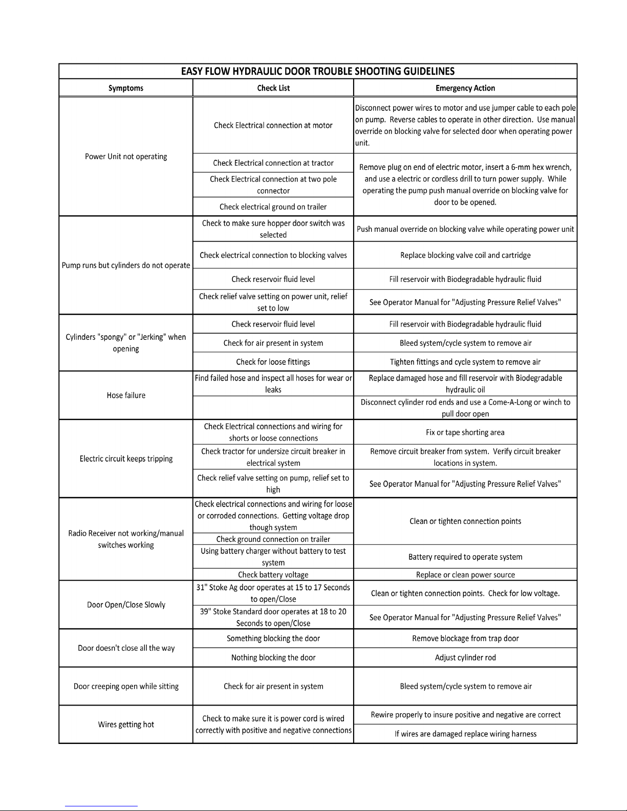
EASY FLOW HYDRAULIC DOOR TROUBLE SHOOTING GUIDELINES
21
Date of Origin – 02/01/08
Page 22

PRESSURE RELIEF ADJUSTMENT
The hydraulic power supply pump is equipped with two pressure relief valves to maximum system
pressure at a safe level. These relief valves are located on each side of the pump, 180 degrees
from each other. At the hose connections the ports on side of the pump are marked with “C1” and
“C2”. The pressure relief on the “C1” side sets the pressure for opening the doors and the relief on
the”C2” side sets the pressure for closing.
When testing or making adjustments on the pressure relief valve system a gauge in both ports of
thepump is required to ensure the most accurate pressure setting. To adjust pressure relief valves:
Setting Relief Valves with Pressure Gauges:
1.Insert pressure gauges in each pump port “C1” and “C2”.
2.A Pressure Relief valve is located on each side of the pump. Use 9/16” socket and loosen the
jamnut on each relief. Do not remove relief valve.
3.Use a 3/16” hex head wrench and turn the relief clockwise to increase pressure setting, counter
clockwise to reduce the pressure. Approximately ¼ turn or 90 degrees equals 250 psi
adjustments.
4.Operate the system until the cylinder is “dead headed” (cylinder at full stroke or fully retracted)
and note the pressure on the gauge. Pumps from factory are preset at 2000 psi.
5.Cycle cylinders in both directions until pressure setting are achieved on both reliefs.
6.Tighten jam nuts and remove gauges.
7.Cycle system to remove any air that may have entered the lines when the gauges were removed.
Setting Reliefs Without Gauges:
1.A Pressure Relief valve is located on each side of the pump. Use 9/16” socket and loosen
the jam nut on each relief. Do not remove relief valve.
2.Use a 3/16” hex head wrench and turn the relief clockwise to carefully bottom out relief valve.
Do not tighten. Tightening relief valve can damage the valve seat.
3.Turn relief valve counter clockwise 1 revolutions. Tighten jam nut s. This will set the pressure at
approximately 2000 psi range. Approximately ¼ turn or 90 degrees equals 250 psi adjustment.
Date of Origin – 02/01/08
22
Page 23

EMERGENCY APPLICATION WITH DRILL
1. Remove Plug from rear of hydraulic power unit motor using a 3/16” Allen wrench.
2. Insert 6-mm hex head wrench attached to an electric drill into opening of motor. Make sure hex
key is properly seated into motor before operating drill.
T op manual override
(Front Hopper Door)
Bottom manual override
(Rear Hopper Door)
3. There are two manual overrides on the blocking valve. The top manual override is for the front
hopper door and the bottom manual override is for the rear hopper door .
To open the Front Hopper door run the drill in reverse direction (counter clockwise) while holding the top manual override button. To close the Front Hopper door reverse the operation of the
drill (clockwise) while holding the top manual override button.
4. For rear hopper repeat step above while holding the bottom manual override button.
23
Date of Origin – 02/01/08
Page 24
ROLL TARP
• The tarp must be kept to a recommended 40-60 lbs.
ATTENTION!
of tension or excessive tarp wear may occur.
• Do not walk or stand on the end caps.
• Do not operate this vehicle at highway speeds, while
the tarp system is in the “open” position.
OPERATING INSTRUCTIONS
1. Crank The Tarp Up
Under The Latch Plate.
2. Bring The Crank Arm
Down To A Vertical
Position.
A decal located on the rear of the trailer gives instructions for the operation of the tarp and adjusting the tarp tension. A caution decal is located on the crank handle with instructions pert aining to
rolling the tarp. Be sure to follow these instructions.
3. Lift The Crank Arm Up
To The Crank Retainer.
T o Adjust The Tarp Tension:
1. Allow The Tarp T o Roll
Down Away From The
Latch Plate.
2. Remove The Crank Arm
From The Splined Shaft.
3. Rotate The Crank One Or
Two Teeth & Reassemble.
IMPORTANT: All tarp bows and cross members must be in place while operating a
loaded trailer . The tarp bows and cross members hold the trailer walls together and prevent side
structure failure. Always close tarp and lock handle into position before moving your trailer to
prevent damage to the tarp system.
Always open the tarp before discharging a load. Failure to do so may damage the trailer and void
the warranty .
If you must remove or reposition the ridge straps or tarp bows during loading, be sure to use a
safe, approved walkway or scaffold. Never walk on the top rail, it is not designed to be a walkway .
TARP TENSION
To Set the Tarp Tension On The Crank:
METHOD ONE:
Hold the crank firmly with both hands
Tighten the tarp by rolling the main t arp tube up under the latch plate
Bring the crank handle down perpendicular to the ground
Continue to tighten by lifting it up (approximately 45 degrees) into the crank retainer:
Repeat this procedure while adjusting the splined shaft and the u•]joint one tooth at a time to
achieve 40 to 60 pounds of tension at the handle end of the crank.
Date of Origin – 02/01/08
24
Page 25
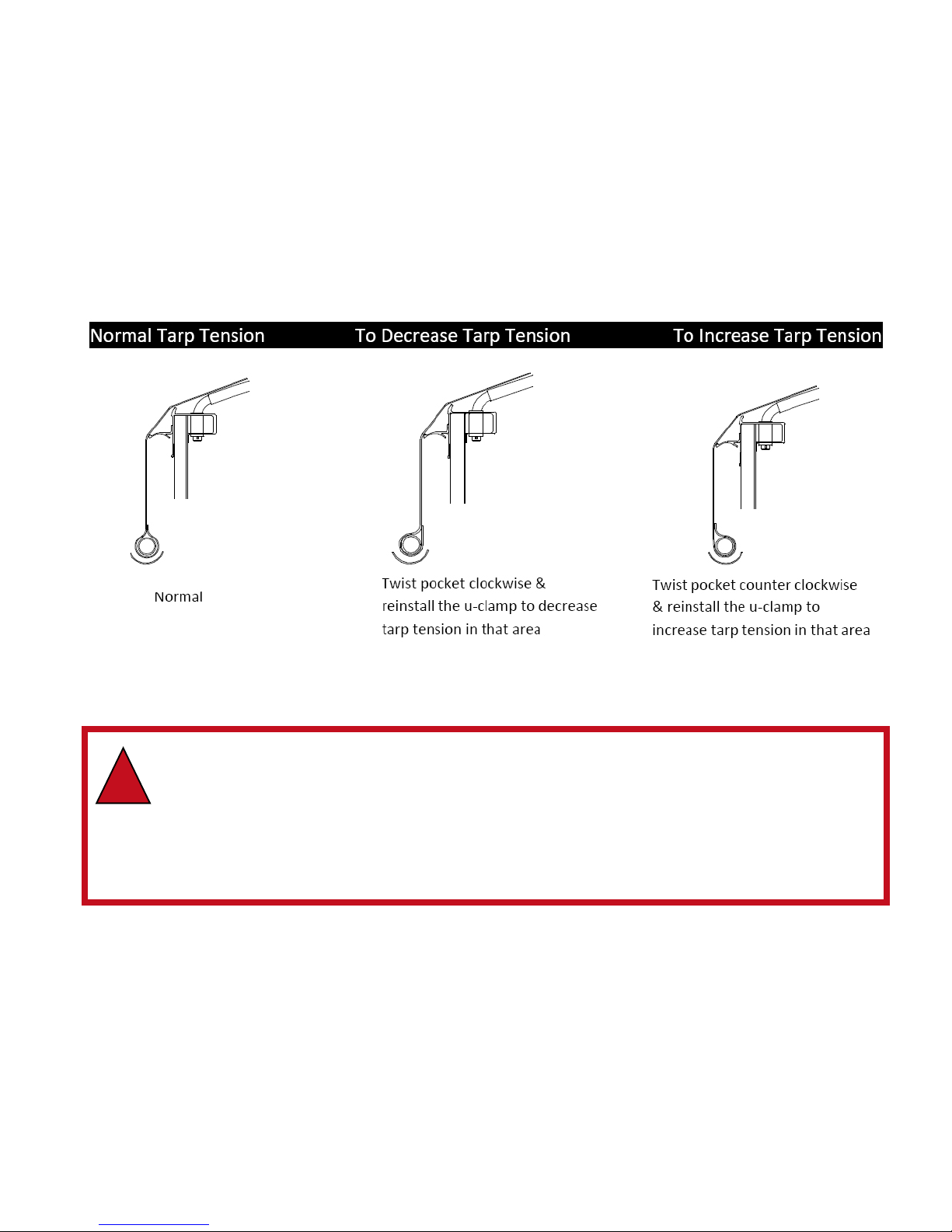
METHOD TWO:
Another method to measure tension is to adjust the tension until you see a slight deflection or a
gradual bend in the crank extension of approximately 1/8”.
After Properly setting the tension on the crank, make sure that the tarp is in the locked position
and check the following:
Check to see that the tarp has equal tension on both the end caps and the bows.
If, for any reason the tarp tension is not the same along the length of the tarp (i.e. tarp twist,
uclamps not aligned, varying box widths from front to back), the u-clamps and the tarp may
need to be readjusted in the loose areas of the tarp.
WARNING! DO NOT walk, stand or climb over or on the end caps. The tarp
caps are designed by the tarp system manufacturer to assist in supporting,
!
tensioning and sealing the tarp. They are not a structural portion of the trailer .
They are purposely light-weight and flexible and are not designed to support a
person’s body weight. Additionally, they are purposely smooth and curved to
assist the tarp in sealing tight, and hence are not designed to be a walk surface.
Failure to follow this warning could result in serious injury or death.
25
Date of Origin – 02/01/08
Page 26

THUNDER ELECTRIC T ARP SYSTEM
OPERATING INSTRUCTIONS - Powering Up or Down the System
To turn the system on or off, locate the “OPEN” and “CLOSE” buttons on the relay module on the
front of the trailer. Push and hold both buttons simult aneously for approximately 3 – 5 seconds.
The red LED will illuminate indicating the module is on and ready for opera¬tion. Alternatively, you
can also press and hold buttons “ON/OPEN” and “OFF/CLOSE” on the RF transmitter for 3 – 5
seconds to power the system on or off.
One Touch Operation:
This operation is fully automated and will stop when proper tension is reached when fully opened
or closed.
To uncover the load, push and hold the button labeled “OPEN” on the relay module or “ON/OPEN”
on the RF transmitter for 1 to 2 1/2 seconds then release. The gear motor will wrap the tarp
around the tarp axle causing the axle to move from the tarped position to the stowed position.
This tarp system can be opened part way and stopped. Anytime you want to stop the t arp system
just hit the “OPEN” or “CLOSE” buttons or “ON/OPEN” or “OFF/CLOSE” on the RF transmitter
and the tarp system will stop. It will not hurt the tarp system to stop part way through the tarping
cycle. When the system shuts down automatically , the system will be set to the recommended t arp
tension. Never travel with the tarp in a partially covered position. The trailer should always be
covered when traveling.
To cover the load, push and hold the “CLOSE” button on the relay module or “OFF/CLOSE” on the
RF transmitter for 1 to 2 1/2 seconds. The springs in the arm will move the tarp from the stowed
position and across the trailer to the tarped position. When the system shuts down automatically,
the system will be set to the recommended tarp tension.
Incremental Operation:
To inch the tarp in either direction press the “OPEN” or “CLOSE” buttons on the relay module
intermittently.
Press and Hold Operation:
To uncover the load using the press and hold feature, push and hold the button labeled “OPEN” on
the relay module or “ON/OPEN” on the RF transmitter . The gear motor will wrap the tarp around
the tarp axle causing the axle to move from the tarped position to the stowed position. Release
the button when the system shuts down automatically . This t arp system can be opened part way
and stopped. Anytime you release the switch the tarp system will stop. It will not hurt the tarp
system to stop part way through the tarping cycle.
Never travel with the tarp in a partially covered position. The trailer should always be covered
when traveling.
To cover the load using the press and hold feature, push and hold the “CLOSE” button on the relay
module or “OFF/CLOSE” on the RF transmitter for greater than 2 ½ seconds. The springs in the
arm will move the tarp from the stowed position and across the trailer to the tarped position.
Release the switch when desired during operation or when the system shuts down automatically .
Date of Origin – 02/01/08
26
Page 27

OPTIONAL ARM ADJUSTMENT
As shipped from the factory , the front and rear arms are set to allow the axle to rest lightly on the
end caps while following the contour as it moves across the trailer .
Different types of loads and conditions may require your tarp to operate differently. For this reason the system has been designed to be very versatile. Please see the steps below to adjust your
arm if need be.
To make the arms carry the axle over heaped loads: Increase the knuckle pressure on the front
and rear arms by moving the spring pin up to the middle hole. If even more lift is desired, move
the spring pin to the top hole.
To increase arm control in windy conditions:
Increase the base pivot pressure on the front and rear arms by moving the spring pin up to the
middle hole. If even more control is desired, move the spring pin to the top hole.
Recommended Maintenance:
All electrical connections should be checked regularly for corrosion. If any con¬nections are found
with corrosion, clean the connection and apply dielectric grease before reconnecting. Electrical
connections can be found at all motors, switches, contactors, limit switches, control boxes and
batteries. Motor mounting bolts should be checked periodically to ensure a minimum torque of 70
in-lbs (5.8 ft-lbs). All mounting hardware should be checked to insure all system components are
securely fastened. Visually inspect all moving parts for abnormal or excessive wear.
Field Troubleshooting Guide:
1. Check main circuit breaker at battery to make sure it is not tripped. If tripped, reset.
2. Check all connections to make sure they are properly secured both at the termi¬nal connection to the stud and where the terminal is crimped to the wire. Loca¬tions to check: battery
connection, circuit breaker near battery , male and female plugs, relay connections, motor
connection.
3. Ensure relay is powered up. If the RF module is on, the LED will be solid red. If the LED is
not on, power the module up by pushing both large buttons simultaneously for 3 – 5 seconds
until LED turns on. If RF module will not power up, remove and replace. If module will power
up but system will not function, proceed to step 2.
4. Disconnect power leads from motor. Check for motor operation in both directions. To do so,
use a set of jumper cables to go direct from battery to motor terminals (+lead to + terminal, lead to - terminal). To reverse direction, remove the jumper cables from terminals and swap
the leads to the opposite terminals (+lead to - terminal, - lead to + terminal). If motor does
not operate in one or both directions, replace motor. If motor operates in both directions,
proceed to step 5.
5. Reconnect input wires to motor and check for operation.
6. Using a voltmeter or test light, check for input power at relay . If using voltmeter , input voltage
should be a minimum of 12V. If voltage is good, proceed to step 6. If no or low voltage,
proceed to step 7.
7. Check voltage at relay output. To do so, connect tester leads to output terminals. Activate in
one direction, check voltage, activate in opposite direction, and confirm voltage. If no or low
voltage, relay must be replaced. If good proceed to step 8.
8. Check voltage at output circuit breaker located near battery . If no or low volt age, replace
circuit breaker.
27
Date of Origin – 02/01/08
Page 28

Error Codes:
Additional T roubleshooting:
Problem Description Solution
T arp will only run one direction Moisture between FWD & REV terminals, clean and add
dielectric
grease
Module clicks, motor will not run M1 & M2 shorted together or motor inter¬nally shorted, find
and
eliminate short
LED Activity Description Duration of LED Activity
Solid Unit functioning properly During Operation
2 blinks System Overload Shutdown 2 times
3 blinks Module Overload Shutdown Until next button press
4 blinks Motor Overheat Shutdown Until next button press
5 blinks High Volt age Shutdown (> 16V) Until next button press
6 blinks Low Volt age Shutdown (<7.5V) Until next button press
Loose connections before control box Check all connections from tractor to
back of control box
Bypass amperage control module in
junction box
Old amperage control module still
connected in junction box
7 blinks Mis-wired or No Load Until next button press
Mis-wired – Power leads crossed Switch the power leads (red stripe
should be positive)
Switch M2 and ground wire
power ground is connected to the
M2 post Check all connections for tightness
No Load – loose connection at the back
of box or at the motor Check with repair facility to replace
wire
broken wire, short in the system
Date of Origin – 02/01/08
28
Page 29

SETTING FUNCTIONS ON REMOTE
Setting function allows functions to be blocked if not required /not going to be used.
1. Open transmitter. Observe flashing light.
2. Press and hold “MODE” button for 10 - 12 seconds until the top light stays lit.
3. Press the “ON/OPEN” button if this function will be used. Select and press the “OFF/CLOSE”
button if you want this function to be skipped.
4. Repeat Step 3 for all five functions.
a. 1 LIGHT - T ARP SYSTEM
b. 2 LIGHTS - FRONT HOPPER
c. 3 LIGHTS - REAR HOPPER
d. 4 LIGHTS - AUXILIARY
e. 5 LIGHTS - AUXILARY
5. When the last function has been selected, the light on the first mode function will stay lit for
approximately 3 seconds to indicate active and return to flashing when process is complete.
WARNING! Make sure all power supply to trailer is disconnected and the ground
!
wire in the nose of the trailer and on the receiver box is disconnected prior to any
welding on trailer . Failure to do so could result in damage to receiver control box!!
29
Date of Origin – 02/01/08
Page 30

THUNDER T ARP RF PROGRAMMING:
1. Power up the RF control module. Press and hold the 2 large “Open” and “Close” buttons for
3 seconds or until the light illuminates to indicate the system is activated.
2. Push and hold the small round button programming and the large “OPEN” button
simultaneously and hold for approximately 6 seconds. The red light will flash rapidly.
3. Open all transmitters to be programmed and observe flashing light to insure transmitter is active.
4. Push “Select” button to select “Tarp System” if flashing light is in another mode on all
transmitters to be programmed.
5. Press the “ON/OPEN” button on transmitter for one second to be programmed. The red light
will stop flashing momentarily and then start. Repeat for all transmitters to be programmed.
Four transmitters can be programmed to each control module so four inputs are required. If
one transmitter is being programmed, the “ON/OPEN” button will required to be pushed four
times. If two transmitters are being programmed then the last transmitter will be required to
press the “ON/OPEN” button three times. The light on the control module will stop flashing
when the four inputs have been received.
6. Close lid of programmed transmitters to power down transmitters.
7. Power down control module by pushing the “Open” and “Close” buttons for 3 seconds on the
power
module or transmitter.
Date of Origin – 02/01/08
30
Page 31

31
Date of Origin – 02/01/08
Page 32

LANDING LEGS
Insure proper engagement of the handle onto the input shaft nut prior to cranking. Use wheel
chocks and lock trailer brakes when uncoupling and coupling tractor and trailer . Insure that the
supporting surface is of adequate strength and stability to support the trailer and the load, if applicable. Also be sure that the lay of the ground is reasonably flat and level. Select high speed or low
speed gear reduction to raise or lower the landing legs. Reference decal on trailer for selection of
mode and direction of rotation.
ACCESS SYSTEM
The trailer is supplied with an access system that is designed and supplied to allow the operator a
means to view the interior of the trailer. It is comprised of a ladder, an observation platform(s) and
a grab handle(s).
!
1. EXERCISE EXTREME CAUTION WHILE CLIMBING ON ACCESS SYSTEM.
2. ALW AYS MAINTAIN 3-POINT CONT ACT.
(2 HANDS & 1 FOOT OR 2 FEET AND 1 HAND)
3. DO NOT WEAR RINGS OR ANYTHING THAT CAN CA TCH ON LADDER.
4. USE LADDER SIDE RAIL FOR HAND HOLD, NEVER USE THE RUNG.
5. NEVER CLIMB OVER THE TOP OF THE TRAILER.
NEVER ENTER THE INSIDE COMP ARTMENTS FOR ANY REASON.
6. NEVER ST AND ON THE ACCESS DURING LOADING OR UNLOADING.
FAILURE TO FOLLOW THESE WARNINGS COULD RESULT IN
SERIOUS INJURY OR DEATH.
TO INSURE OPTIMUM PERFORMANCE OF THE ACCESS SYSTEM, IT
SHOULD BE INSPECTED PRIOR TO USE FOR ANY VISIBLE SIGNS OF
DAMAGE. REPAIR OR REPLACE ANY ACCESS SYSTEM COMPONENT
THAT HAS BEEN BENT, CRACKED, WORN OR OTHERWISE DAMAGED. DO NOT MODIFY THE ACCESS SYSTEM WITHOUT CONSULTING WITH TIMPTE TRAILER CO.
WARNING
Date of Origin – 02/01/08
32
Page 33

LIFTABLE, REGULA TED AXLE
For trailers equipped with a Liftable, Regulated axle, the air controls are on the roadside near the
suspension of your trailer. This box contains a 160 p.s.i. regulator along with a locking detent lif t
control valve, and a manually adjustable regulator knob. The regulator is adjusted manually to
control the pressure of the lift axle ride bags.
T o control the load on your lif t axle, with the trailer loaded, pull the regulator knob and turn to the
desired pressure. This can be accomplished by placing the lift axle on a scale while the adjustment is taking place. Once the desired load is on the axle, push in the knob to lock the adjustment
in place.
lift or lower the axle, rotate the locking detent lift control on the valve counterclockwise Y4 turn to
To
a horizontal position to lift and then back clockwise Y4 turn to a vertical position to lower the axle.
The lift axle is considered a ‘pushing axle’ and it is very important to always lift the axle when the
trailer is empty and lower the axle when
the trailer is loaded.
If the axle were to be connected to electrical power, the lift has a personal safety feature that will
allow the axle to lift when the power is disrupted.
NOTE: Loading the axle should never exceed the wheel, tire, or axle rating.
Locking Dentent
Lift Control
Manually
Adjustable
Regulator
33
Date of Origin – 02/01/08
Page 34

GENERAL MAINTENANCE
AVOIDING CONT AMINATION
The operator has the best opportunity to avoid contamination between commodities. It is critical
that the operator clean and maintain the trailer interior and trap frame areas to avoid contamination. The interior hopper, dividers, etc. should be inspected and cleaned thoroughly by the operator as required. Use a broom or a high pressure sprayer to clean the interior surfaces including the
dividers, wall liners and interior tub panels. Do not use a high pressure sprayer for trap frame
cleaning and washing. High pressure water could enter and damage the bearings. Access to the
interior of the trailer should be from underneath through the trap door opening. Never climb over
the top of the trailer into the interior . See section below for trap frame maintenance.
TRAILER WASHING
Washing the trailer is an important step in decreasing future maintenance. The trailer should be
washed with soap and water using a relatively soft bristle brush. V arious chemicals can cause
severe corrosive damage to aluminum. The use of acid in any concentration to clean the trailer
will void the warranty .
There are many different types of chemicals used today to de-ice the roadways. Many of these
can cause severe damage to the steel substructure of the trailer and diminish the appearance of
the aluminum and stainless steel components if not kept properly and regularly washed away .
A number of products hauled in the trailer will also lead to corrosion if the products are allowed to
build up. Products that build up on the aluminum and steel members in the suspension subframe
and upper coupler area should be routinely washed off.
CORROSIVE DETERIORA TION
V arious chemicals can cause severe corrosive damage to your aluminum grain trailer. T o prevent
severe damage to your trailer due to corrosion, contact T impte Trailer Company Product Engineering to verify that the materials you are hauling are compatible with the materials used in the
construction of the trailer.
Corrosive deterioration caused by incompatible materials could void all or part of the
trailer warranty .
The most important preventive maintenance step to avoid corrosion is cleaning; your trailer should
be washed out after each load to minimize corrosion when hauling such items as salt, fertilizer ,
etc.
Date of Origin – 02/01/08
34
Page 35

TRAP FRAME/TRAP OPERA TOR MAINTENANCE
The following areas (below) should be inspected regularly between loads and commodities.
• Doors (T op/sides/underside)
• Trap frame structure
• Roller bearings
• Gear rack
• Cross shaft and flange bearings
It is critical that the trap frame area be maintained properly for trouble free operation. Clean these
sections with a hand brush, compressed air (50 PSI max) or both between loads to avoid contamination. Do not use high pressure sprayer as bearings could be damaged.
T o maintain proper trap door operation and ease of opening, the mechanism must be properly
adjusted and lubricated.
The trap operator drive mechanism (gear rack and cross shaft gear) interfaces must be kept
properly aligned and free of debris and corrosion to enhance freedom of movement. Flange
bearings should be greased regularly , depending on frequency of operation. Timpte recommends
the operator grease bearings monthly (failure to do so may void warranty).
Use the following procedure to readjust the trap door and gear rack assembly .
35
Date of Origin – 02/01/08
Page 36

Date of Origin – 02/01/08
36
Page 37

37
Date of Origin – 02/01/08
Page 38

AIR HAMMER (VIBRA TOR) MAINTENANCE
The air hammer employed to help dislodge commodity should be lubricated on a regular basis.
The air hammer manufacturer recommends a SAE 10 or lighter oil for this purpose. Frequency of
lubrication is directly related to volume of usage. The operator should lubricate the air hammers
(vibrators) prior to each use or maintain oil in reservoir if equipped with self-lubricating system.
NOTE: The operator must confirm that all air hammers are securely located in the mounting brackets and locked into place prior to usage. Failure to locate and lock air hammers
into position properly could result in serious personal injury or damage to the trailer. Do
not exceed 80 P.S.I. while operating piston vibrator. Failure to follow operating instructions properly could void the warranty.
TROUBLE-SHOOTING:
1.Vibrator will not start:
a. Check to see that quick-opening valve is properly installed.
b. Vibrator should be within 5 feet of operating valve.
c. Be sure vibrator has adequate air pressure and volume
available.
d. Check for broken or missing spring on horizontal mount
units.
2.Vibrator is sluggish and slow to start.
a. Check for adequate lubrication.
b. Check for leaking airline or defective operating valve.
c. Check air supply for pressure and volume.
d. Scale or other contaminants may need to be removed from interior.
FILTER/LUBRICATOR/REGULATOR
SPECIFIED OIL
• SAE 10 or lighter air tool oil
FILLING WITH OIL
• Remove the reservoir from the FLR assembly
• Fill the reservoir with specified oil until oil appears in the small window. NOTE: If filling level is too
high, oil can reach the system and damage it.
• Place the reservoir on the device until it engages audibly.
ADJUSTMENT SCREW
ADJUSTMENT SCREW
Date of Origin – 02/01/08
38
Page 39
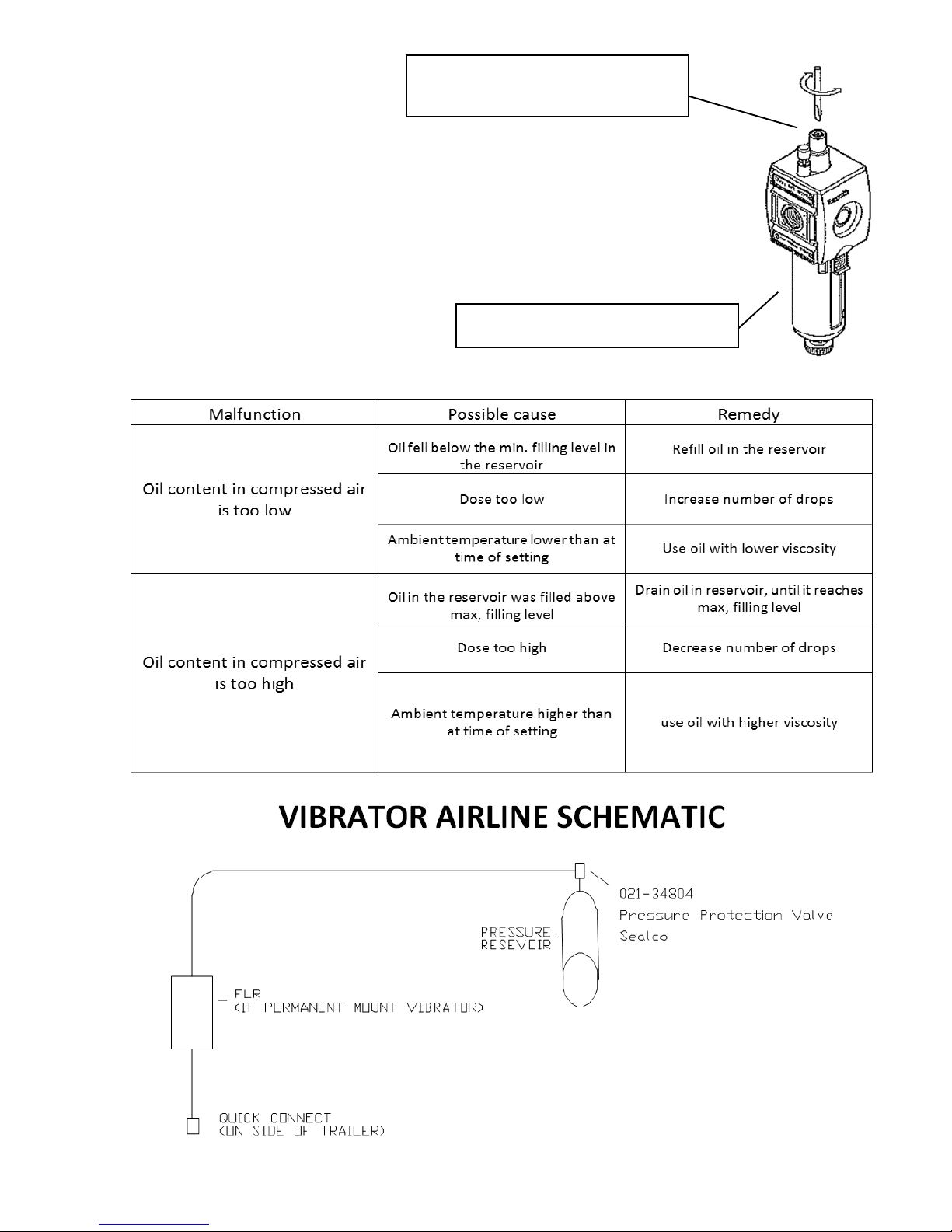
CLEAR PLASTIC NIPPLE WITH
GOLD ADJUSTMENT SCREW
SETTING THE OIL AMOUNT
• Set the oil amount using the metering screw on the standard oil-mist
lubricator’s drop attachment.
• Determine amounts of oil discharged by observing the number of
drops in the drop attachment. S tandard value: 1-2 drops/min
(qv = 1000 NI/min)
OILER SECTION ONL Y SHOWN
TROUBLE-SHOOTING:
39
Date of Origin – 02/01/08
Page 40

HUB AND BEARINGS
HUB MAINTENANCE
Check wheel studs for good condition – no stripped threads – no bent or loose studs. Replace any
broken or bent studs or studs with damage to the threads. When a broken stud is replaced, the
stud on each side of it should be replaced at the same time. If more than two studs on the same
hub are broken, replace all of the studs.
WHEEL BEARING INSPECTION
Periodic inspection of wheel bearings and lubricants as well as regular lubricant changes are
necessary for good maintenance and maximum wheel bearing life. The hub and/or wheel assembly
must be properly cleaned to obtain optimum bearing life. This step also applies to field service.
When adding or checking oil level, make certain cap and plug are clean. This step will minimize the
possibility of dirt and road grime entering the system.
WHEEL BEARING ADJUSTMENT
1. Install adjusting nut so that pin on nut faces away from the hub.
2. Tighten inner nut to 200 ft. lbs. while rot ating the hub in both directions.
3. Completely loosen the inner nut, then retighten to 50 ft. lbs. while rotating the hub in both
directions.
4. Loosen the inner nut ¼ turn. Do not include socket backlash in the ¼ turn.
5. Install the lock washer . If the hole in the lock washer is not aligned with inner nut pin, remove
the washer , turn it over and reinstall. If the washer hole is still not aligned with the pin, loosen
the inner nut slightly until the hole and pin are aligned.
Note: The washer may have to be reversed again with minimum loosening of the nut.
6. Install the jam nut; Torque to 300 ft-lbs.
7. Check the hub end play with a magnetic base and dial indicator .
a. Place the magnetic base and indicator on the end of the spindle. Touch dial indicator
stem to hubcap gasket face.
b. Slightly rotate the hub & drum in both directions while pushing inward until the dial
indicator reading does not change.
c. Set the dial to zero.
d. Slightly rotate the hub & drum in both directions while pulling outward until the dial
indicator reading does not change.
e. Read the end play from the dial indicator .
8. End play between .001 and .005 is acceptable.
a. If the end play is less than .001, loosen the jam nut; Repeat steps 1 through 8, and
retorque to 300 ft. lbs.
b. If the end play is greater than .005, increase the jam nut torque to 300 ft. lbs.
9. Repeat Step s 6 & 7 as necessary until the end play is within the accept able range.
10.Bend tabs on lock washer over opposite flats of the jam nut.
BEARING LUBRICANT
The lubricant change interval depends on the type of lubricant used; oil or semi-fluid grease. Oil
levels should be checked as part of the daily inspection. Oil should be changed whenever seals are
replaced, brakes are relined, or at least every 12 months or 100,000 miles. Fill hubs with new oil to
the level indicated on the hub window using HD80-90W heavy duty oil with an API rating of GL-15 or
GL-4.
CAUTION! DO NOT overfill oil. Oil seal damage may occur due to excessive
!
Date of Origin – 02/01/08
internal pressure.
40
Page 41

Grease lubricated wheel ends should be changed whenever seals are replaced, brakes are
relined or at least every 12 months or 100,000 miles with NLGI Grade 1 or 2 grease.
To install semi-fluid grease
1. Pack both bearings with grease by forcing grease into the cavities between rollers
and cage from the large end of the cone.
2. Apply a light coat of grease to the spindle bearing journals.
3. Install the inner bearing, inner seal and hub.
4. Fill the cavity between the bearing races with grease up to the smallest diameter of the
bearing cups.
5. Install the outer bearing and adjust end-play as noted in the “Wheel Bearing Adjustment
Procedure” section.
6. Apply a light coat of grease to the interior of the hubcap and wheel retention hardware
to indicate what lubricant is installed as well as to help prevent corrosion of these parts.
BRAKES
Proper maintenance of the brakes is vitally important. This includes lining inspections and brake
adjustments. A schedule for periodic adjustment, cleaning, inspection and lubrication of the brake
equipment must be made according to duty cycle and type of operation.
Brakes must be adjusted as frequently as required for correct operation and safety . The adjustment
must give correct clearance between the lining and drum, correct push rod travel, and correct balance between the brakes. Improper or inadequate lubrication is the leading cause of dragging
brakes/premature brake wear.
Brakes must be cleaned, inspected, lubricated and adjusted every time the wheel hubs are removed.
During a major overhaul, the following parts must be carefully checked and replaced with genuine
replacement parts if required.
1. Backing plates or spiders for distortion and loose bolts.
2. Anchor pins for wear and correct alignment.
3. Brake shoes for wear at anchor pins or roller slots.
4. Camshaft and camshaft bushings for wear .
5. Shoe return springs for wear and loss of strength.
6. Brake linings for grease on the lining, wear , chip s, and loose rivets or bolts.
7. Drums for cracks, deep scratches, heat checking or other damage.
NOTICE:
Wheel bearings must be correctly adjusted before brake
adjustments are made.
NOTICE:
Brake linings must not be permitted to wear to the point
that the rivets or bolts touch the drum.
See the manufacturer’s maintenance manual for more information and details on brake maintenance, repair and trouble shooting.
41
Date of Origin – 02/01/08
Page 42

Air leaks at spring brake chambers, reservoir fittings, drain valves, drop hoses, and connections
can cause the air system to perform less efficiently and the compressor to cycle too frequently
and may eventually result in dragging brakes.
If you suspect air system problems in either service brakes or spring brakes, don’t hesitate –
service the brake system immediately;
Trouble shooting the air brake system:
• Use the “soap bubble” test at all connections throughout the air system to detect
external leaks
• Threaded connections at the ECU
• Threaded connections at the pressure protection valve
• Any and all push-in fittings
• Check for exhaust leaks at all valves to detect internal leaks.
• Check the actuator and spring brake push rod for proper movement in operational modes.
NOTE: Never splice air brake hoses within the air brake system. This action will void part or all of
the trailer warranty .
Date of Origin – 02/01/08
42
Page 43

AIR BRAKE SYSTEM - TROUBLESHOOTING GUIDE
LEGEND
TPV = TRACTOR PROTECTION V AL VE
EV - EMERGENCY V AL VE (REFERENCE PG 38 BUBBLE 22)
SRV - SERVICE RELA Y V AL VE (REFERENCE PG 38 BUBBLE 6)
system. Drain resevoirs before removing air lines, hoses, valves,
or servicing valve plug units. Consult spring brake manufacturer’s
CAUTION! Block wheels before servicing trailer air brake
recommendations before working on spring brake chambers.
!
43
Date of Origin – 02/01/08
Page 44
BRAKE CONTROLS
Proper operation of the brake system requires a good, clean seal between the glad hands. Inspect the rubber washer on the glad hands for damage. Inspect the glad hands for cracks in the
metal parts. The glad hands have a screen filter and must be cleaned. Check air hoses for cracks
and leaks. Check the operation of the brakes and slack adjusters. Drain the water from the air
brake system each day by opening the drain cocks on the bottom of the air tank(s). Periodically
check and clean the filter element on the air line filter, mounted directly behind the Control side
glad hand. Observe the ABS status indicator light for proper operation as found under the ABS
heading in the SAFETY section.
IN-LINE AIR FILTER
This trailer is equipped with an in-line air filter, Control side, which is located on the nose of the
trailer, to assist in protecting the air system brake valves. The number one cause of ABS valve failure
is contamination in the air supply from the tractor . This filter will help in minimizing those problems. To
operate properly and provide the most protection possible, the filter should be inspected and
cleaned every 3 to 4 months. Proper use and maintenance of the filter will help extend the life of the
ABS ECU and will extend the warranty on the ABS ECU.
NOTICE:
T railer is equipped with an in-line filter to
assist in protecting the air system brake valves.
The in-line filter is serviceable and should be
inspected and cleaned every 3 to 4 months.
See TP-03100 for maintenance instructions.
www.meritorwabco.com
899 201 842 4
AIR SYSTEM COLD WEA THER OPERATION
Reservoir Draining – Daily reservoir draining is the most basic step in reducing the possibility of
freeze up.
Thawing Frozen Air Lines
1. Maintain freeze prevention devices to prevent frozen air lines. Daily check evaporators or
injectors. Check the air dryer for proper operation and change the desiccant when needed.
2. Thaw out frozen air lines and valves by placing vehicle in a warmed building. This is the
only method for thawing that will not cause damage to the air system or its components.
3. Do not apply an open flame to air lines and valves. Beyond causing damage to the internal
non-metallic parts of valves and melting or burning non-metallic air lines, THIS PRACTICE
IS UNSAFE AND CAN RESULT IN VEHICLE FIRE.
CAUTION! Do not pour any alcohol into gladhands. Doing this will result in valve
!
Date of Origin – 02/01/08
failure and will void the warranty . Fluid in air lines can also cause a fluid lock and keep
Rev 9/08
44
Page 45

AIR BRAKE PIPING SCHEMA TIC
45
Date of Origin – 02/01/08
Page 46
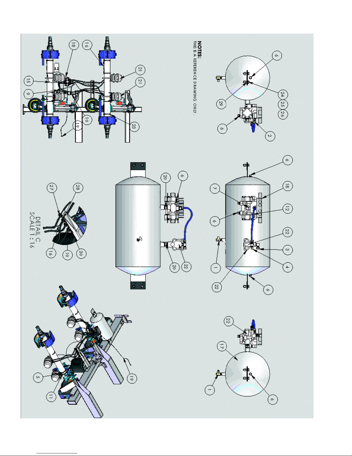
AIR BRAKE PIPING SCHEMA TIC
Date of Origin – 02/01/08
46
Page 47

CHECKING SPRING BRAKES
Spring breaks must be inspected on a routine basis to insure proper operation. Inspection is
recommended a minimum of every 3 months or 25,000 miles.
WARNING! Always chock wheels to prevent the vehicle from rolling before per-
!
1. Check overall condition of the foundation brakes including drums, shoes, lining, retainers, return
springs, bushings and rollers. Replace any damaged or worn components per manufacturer’s
specifications.
2. Check for obvious structural damage to the spring brakes, brake adjusters, or cam shafts and
replace any damaged or worn components per manufacturer’s specifications.
3. Hook up appropriate air supply and release parking brakes. Apply and fully release Parking Brake
several times while watching for brake adjuster movement. Adjusters should apply and retract at
relatively the same distance for all wheel positions.
4. T o verify equal push rod movement, measure each push rod from the Face of the Air Brake Cham-
ber to the Center of the Clevis Pin with the brakes Fully Set or Parked. Apply air to the chambers to
release the parking brakes and re-measure all wheel positions. All strokes should be within 1/8" of
each other .
5. Applied Stroke at 90 to 100 psi can also be used to measure in a similar way as in step #4. Apply
Service Brakes instead of setting Spring (Emergency) Brakes and record before and after push
rod measurements. Measured push rod stroke should not exceed the recommended maximum
readjustment limit of 2" for Standard 30/30 chambers and 2 1/2" for Long Stroke 30/30 chambers.
forming any brake maintenance.
AUTOMATIC SLACK ADJUSTERS
Effective 10/20/94 all semi-trailers with air brake systems were required to be built with automatic
slack adjusters to assist in maintaining the braking system performance. The automatic slack
adjusters should be periodically checked to insure that they are performing correctly and should
be lubricated on a regular schedule or at least every six months.
The following procedure can be used to check the in-service adjustment of air chamber push rod
travel (adjusted chamber stroke) on trailer air brakes with automatic slack adjusters.
1. Connect an adequate air supply to the SUPPLY glad hand of the trailer’s air system.
2. Increase the air pressure to 100 psi minimum to release the auxiliary spring brake chambers.
3. Determine the size and type of brake chamber you are inspecting.
4. With the brakes NOT APPLIED measure the distance from the bottom of the air brake
chamber to the center of the large clevis pin on all wheel positions. Record each measurement.
5. Connect a second air supply to the CONTROL glad hand of the trailer’s air system.
6. Increase the air pressure of the second air supply to 85 to 90 psi to apply the service
brakes.
7. With the SERVICE BRAKES APPLIED measure the distance from the bottom of the air
brake chamber to the center of the large clevis pin on all wheel positions. Record each
measurement.
8. Calculate the adjusted chamber stroke of each brake. Subtract the dimension that was
measured in Step #3 from the dimension that was measured in Step #6. The difference
between the two dimensions is the adjusted air brake chamber stroke. The adjusted air
brake chamber stroke must not be greater than 2” for 30/30 chambers and 1 ¾” for 24/20
chambers. If the adjusted air brake chamber stroke is greater than the dimensions listed,
inspect the automatic slack adjuster for wear or damage. See manufacturer’s recommendations for repair or replacement.
47
Date of Origin – 02/01/08
Page 48

WHEEL ASSEMBLIES
Inspect parts and components for damage. Replace any defective parts.
Use only correctly matched parts when assembling and installing wheels. Incorrect parts can
result in separation of the wheel components which can lead to an accident.
Assembling painted, dirty, or rusty components can prevent proper mating of parts. Make sure all
mounting surfaces are clean and free of rust, dirt, or excessive paint.
Make certain all tires are matched to the same rolling circumference per the tire manufacturer’s
instructions. Do not use tires that do not meet this criterion. Doing so may result in unstable
operation that can significantly reduce service life.
All components must be correctly installed and fasteners tightened to the recommended torque to
assure maximum service life in accordance with the manufacturer’s instructions. Failure to do so
may result in serious injury or death.
WHEEL INST ALLATION
Hub piloted disc wheels have stud holes that are drilled straight through the wheel. Pilot bosses
machined on the hub fit tightly into the center of the disc wheel. This supplies the alignment of the
wheel to hub. Hub Piloted wheels are secured to the hub with flanged nuts.
Installation of a Hub Piloted Wheel
1. Be sure not to mix Hub Piloted and Stud Piloted disc wheels.
2. Use the correct flange nuts to match your wheels. Failure to do so may lead to loose
wheels which significantly reduce product life and may result in a crash. Before proceeding
with the installation of the disc wheels make certain that you are using the proper flange
nuts. The Hub Piloted mounting uses M22 x 1.5mm pitch metric thread series nuts. The
stud standout should be at least 2.16”. All studs have right hand threads.
3. Rotate the hub so that one of the intermittent pilots is located at the top position.
4. Position the inner disc wheel over the studs and wheel pads being careful not to damage
the stud threads or the pilot diameter of the wheel. Make sure the disc wheel is flat against
the mounting surface and there is clearance between the disc wheel taper and the brake
drum.
5. Position the outer disc wheel over the studs and wheel pilot pads being careful not to
damage the stud threads or the pilot diameter of the wheel. Be sure the valve stems for
both the inner and outer tires are accessible.
6. Install the flange nuts and tighten to 50 ft. lbs following the sequence shown. Note: On two
piece flange nuts, apply a drop of oil between the nut and washer . Make sure the flange
washer is not seized to the nut. Do not lubricate the mounting surface of the drum or wheel,
or the stud threads.
7. Check both disc wheels for proper positioning on pilots and proper sealing against the
drum/hub assembly . If they are not, loosen the flange nuts and reposition the wheels.
8. Tighten the flange nuts to 450 to 500 f t. lbs. dry thread torque following the sequence below .
Recheck the torque after the first 50 to 100 miles of service and at every pre-trip inspection.
Date of Origin – 02/01/08
48
Page 49

!
WARNING
1. Read and understand this warning and the installation, Service and Safety Instruction Manual to
understand all safety precautions, proper operation, and maintenance of your Webb hub. Failure to do
so could result in death or serious injury and could result in a compromise of your vehicle’s safe
operation through loss or failure of a wheel or the compromise of the braking system. Copies of the
installation, Service and Safety Instruction Manual are available, free of charge, from Webb Products,
Inc., upon request.
2. Always use a properly installed calibrated torque wrench to assure proper torque. Under torque and over
torque can cause thread and/or nut damage and could result in the loss of a wheel. Failure to ensure proper
torque could result in death or serious injury and could shorten the expected life of this product.
3. Recheck torque after the first 50 to 100 miles of service. Parts may seat naturally, causing the torque to drop.
A drop in torque could result in the loss of a wheel. Proper torque is essential to avoid damage or compromise
of your vehicles safety. Failure to ensure proper torque could result in death or serious injury.
2310 INDUSTRIAL DRIVE, S.W.
CULLMAN, ALABAMA 35055
256-739-6660 WWW.WEBBWHEEL.COM
(FOR PILOT MOUNTED DISC WHEELS)
APPLIES TO M22 X 1.5 STUDS / TWO PIECE FLANGE NUT.
All threads are right hand metric.
Tighten Flange Nuts to 50 ft.lb. using sequence
shown.
Check Disc-Wheels for proper positioning on pads
and proper seating against flange.
Tighten Flange Nuts to recommended torque using
sequence shown.
RECOMMENDED TORQUE: 450 - 500 FT. LBS.
HUBS
8 - 10 STUD HUBS
TIRE CHANGE PROCEDURE
PRECAUTIONARY NOTES:
Keep unnecessary personnel away when raising and lowering trailer and changing tires.
Do not climb under a raised trailer .
Do not leave a raised trailer unattended.
Avoid raising a loaded trailer whenever possible.
1. Position trailer on a level, hard surface capable of supporting the total vehicle weight
and lifting equipment.
2. Set brakes and block wheels at other locations to prevent movement.
3. If a loaded trailer must be raised for changing tires, take appropriate precautions to
reduce risk of tipping, load shifting, or structural damage. If necessary , use two lifting
devices and raise both sides of the trailer evenly to prevent leaning and tipping.
4. Position the jacks or lifting devices under the axle, as close to the outer end as possible. Use care to avoid placement that will cause contact and damage to other components such as brake chambers, cam shafts, U-bolts, and slack adjusters.
5. Raise the trailer at a slow , steady rate until the tires to be removed are off the ground. If
using two lifting devices, raise both sides of the trailer evenly to avoid leaning and
tipping.
6. Position trailer supports under trailer frame or axle to prevent unexpected lowering of
the trailer.
7. Remove the nuts securing the tires and remove the tire(s) using a tire fork or similar
device to lift the tire(s).
8. Install the replacement tire(s). Refer to the appropriate section of the Owner’s Manual
for specific instructions for wheel installation.
9. T orque the securing nuts to 450 to 500 f t. lbs. (dry)
10. Remove trailer supports
1 1. Lower the trailer to the ground at a slow , steady rate. If two lifting devices are used,
lower both sides evenly to avoid leaning and tipping.
Watch for pinch points to ensure no electrical or pneumatic lines will be damaged.
12. Remove lifting devices and check wheel nuts to ensure they are torqued to the specified values.
13. Inspect suspension components for damage or improper adjustment resulting from
raising and lowering the trailer. Rep air any damaged components as necessary .
14. Remove blocks from wheels.
49
Date of Origin – 02/01/08
Page 50

AXLE ALIGNMENT
Proper axle alignment is a vital part of trailer maintenance. Failure to maintain proper alignment
may cause tire scrubbing and suspension component strain. Y our trailer’s alignment should be
checked regularly and the axles realigned when required to prevent unnecessary tire wear.
1. T o properly align the suspension make sure the trailer is unloaded. Free the suspension of
any “binds” by first pushing the trailer backwards and then pulling it forward a sufficient
distance. Check axle alignment with the trailer on a level surface with the trailer level both
side to side and front to back, with tires properly inflated, trailer securely restrained, trailer
brakes (service & parking) released and with the trailer ride height valve properly set (if an
air ride).
2. Check each dual tire set. Tires of each set must be matched to a maximum of 1/8” tire
radius. Air pressure must be the same in all tires.
3. Using a steel measuring tape, measure from the center point on the bottom of the king pin
to identical locations on each end of the front axle using a consistent amount of pressure on
the tape measure.
4. If these measurements differ by more than 1/16”, adjust one end of the front axle forward or
rearward until identical measurements are obtained on both ends.
5. After the front axle is aligned and secured, measure from the end of the front axle to the end
of the rear axle on each side.
6. If these measurements differ by more than 1/16”, adjust one end of the rear axle forward or
rearward until identical measurements are obtained on both ends.
Spring suspensions are equipped with screw adjusted torque arms located on the driver’s left
side of the trailer. Adjustment of the alignment is accomplished by turning the torque arm in or out,
depending on the adjustment required.
1. Loosen the radius rod clamp bolts.
2. Move the left end of the axle forward (shorten the alignment measurement) by turning the
torque arm to make it shorter.
Move the left end of the axle rearward (lengthen the alignment measurement) by turning the
torque arm to make it longer .
3. Check the alignment measurements. Repeat the adjustment in Step #2 as necessary .
4. When the axle is correctly aligned, tighten the radius rod clamp bolts to 130 ft. lbs. oiled or
170 ft. lbs. dry .
Note: Check the clamp bolt torque within the first 50 to 100 miles of operation following alignment.
Air ride suspensions are equipped with mechanisms to allow the movement of one end of the axle
forward or rearward for the purpose of aligning the trailer axles.
Inspect the hanger pivot bushings as well as all other suspension components before adjusting the
alignment.
Date of Origin – 02/01/08
50
Page 51

The SAF Holland RL-230 or RL-250 suspensions use a bolt at the suspension pivot
connection with an eccentric collar to allow for adjustment for axle alignment.
1. Loosen the 1 1/8” pivot bolt lock nut on the inside of the suspension hanger.
2. Rotate bolt head clockwise to move the axle forward (to shorten the alignment measurement) or rotate bolt head counter clockwise to move the axle rearward (to lengthen the
alignment measurement).
3. Snug the hanger bolts to 200 ft. lbs. and check the alignment measurements. Loosen the
nut and repeat the adjustments in Step #2 if necessary
4. When the axle is correctly aligned, re-torque the lock nut on the pivot bolt to 550 ft. lbs.
The SAF Holland CB2300 & CBX23 suspension with the Quik Align feature uses a bolt on
the front the suspension hanger to allow for adjustment for axle alignment.
1. Using a hand wrench, rotate the Quick Align bolt clockwise to shorten the alignment measurement or counter clockwise to lengthen the alignment measurement.
AIR-RIDE SUSPENSION SYSTEMS
See suspension manufacturer’s decals prominently displayed on trailer body and manufacturer
literature kit supplied with trailer for details and specific instructions on the care and maintenance
of the air ride suspension.
Retorque the suspension fasteners after the first 3 months of use or 5,000 miles of operation after
an alignment, at regular periodic maintenance checks and at every brake relining per the
manufacturer’s directions.
NOTE: Never move an air ride trailer without first fully inflating the air springs – failure to
do so could cause damage to the trailer and suspension and will void the warranty .
51
Date of Origin – 02/01/08
Page 52
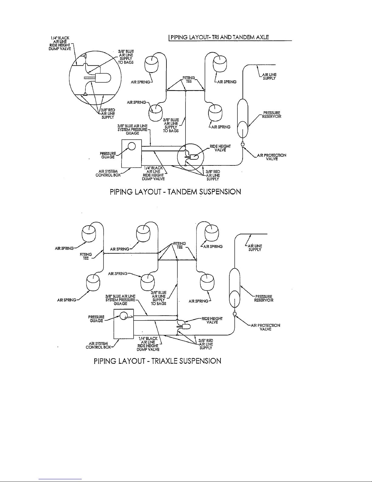
AIR RIDE SUSPENSION SCHEMA TIC
Trouble shooting hints for air piping systems:
• Check all push-in and T-fittings. Are they locked into place?
• Check all threaded connections to the spring brakes
• Check push-in fittings at the lift box (if applicable)
• Check push-in fitting at ride height box (bottom of the box)
• Threaded connections at the gladhands on the nose of the trailer
• Check push-in fittings at top of air bags
• Check for adequate supply of air from tractor
Is volume and pressure great enough to open Pressure Protection V alve
• Check free travel and response of Ride Height Valve
Date of Origin – 02/01/08
52
Page 53
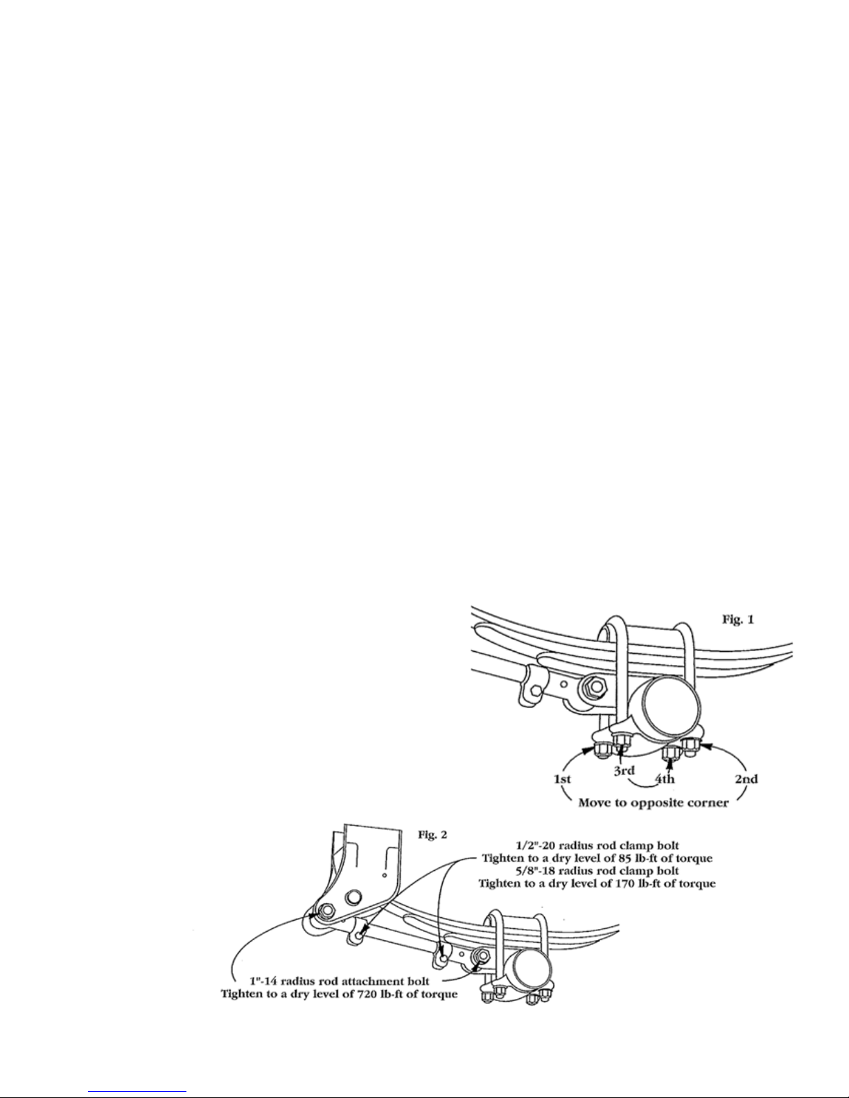
SPRING SUSPENSION MAINTENANCE
After 500 miles or not later than 30 days after purchase, carefully check all fastener torques on
the spring suspension and make any adjustments necessary .
Components New Oiled Torque Clean Dry Torque
1 1/8-7 Rocker Bolt 590 ft. lbs. 790 ft. lbs.
1-14 Radius Rod Bolts 540 ft. lbs. 720 ft. lbs.
¾-16 U-Bolts 310 ft. lbs. 420 ft. lbs.
5/8-18 Radius Rod Clamp Bolt 130 ft. lbs. 170 ft. lbs.
5/8-18 Spring Retainer Bolt s 35 ft. lbs. 50 ft. lbs.
The axle alignment should be checked and corrected if necessary after this initial break in period.
Check all suspension bolts no less than every 4 months. They should be tightened to the above
torque specifications. (Remember lubricants or sealants on the threads reduce torque reading
and paint, corrosion, or road debris on the threads increase readings). Check for and replace
worn bushings in the equalizer and in the torque arm eye ends. Use a good rubber lubricant on
bushings before installation to prevent damage during installation. Be sure radius rod bolts are
tightened back to 540 ft. lbs. (oiled) after replacing any torque arm bushings, and tighten equalizer
rocker bolts back to 590 ft. lbs. (oiled) after replacing equalizer bushings. Check the equalizers to
see that there is no obstruction to their movement during operation. If equalizer movement is
restricted by an obstruction, the axle “walk” will not be sufficient and damage could result.
AXLE CLAMP GROUP AND SPRINGS -
1. Check the torque on the U-bolt nuts by alternately tightening opposing corners of the clamp
assembly.
See Figure 1.
a. When using 7/8” - 14 U-bolts, the nuts should be torqued to a dry level of 470 lb-ft.
b. When using 3/4” - 16 U-bolts, the nuts should be torqued to a dry level of 420 lb-ft.
Always carefully inspect the spring and axle
clampcomponents for any signs of wear or
cracks, andreplace if visible wear or cracks
are present.
RADIUS RODS -
2a. The 1” - 14 radius rod attachment bolts at the hangers
and spring seats should be tightened to a dry level of
720 lb-ft. of torque on both the adjustable and non-adjustable
radius rods. See Figure 2.
53
Date of Origin – 02/01/08
Page 54
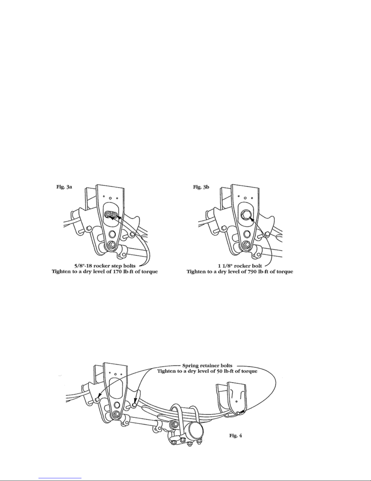
Loose operation of this bolt can result in wear requiring that new components be installed to avoid
structural damage. During your visual inspection, if you observe any visible wear or loosening in
the bushings, it is imperative that you immediately replace the radius rod bushing and bolt. Failure
to replace these components will result in damage to the hanger , spring seat, and/or radius rod.
2b. Next check the 1/2” - 20 radius rod clamp bolt, which should be tightened to a dry level of 85 lb-ft.
of torque. The 5/8” - 18 radius rod clamp bolt should be tightened to a dry level of 170 lb-ft of torque.
See Figure 2. If the clamp bold has not been properly maintained, then wear between the radius
rod screw and the eye end may be observed. If so, then the entire radius rod must be replaced.
Simply retightening or replacing the clamp bolt will not correct the problem.
ROCKER BUSHINGS -
3. The recommended torque values for the rocker bushing clamp bolts are different for each
model.
a. If you are working on the 7700 model suspension, the 5/8” -18 rocker step bolts should
be tightened to a dry level of 170 lb-ft of torque. See Figure 3a.
b. If you are working on the 9700 model suspension, the single 1 1/8” - 7 rocker bolt
should be tightened to a dry level of 790 lb-ft of torque. See Figure 3b.
During your check, if the bolts are loose a detailed inspection of the rocker is important to ensure
that no structural damage has occurred. One way this can be done is by raising the trailer until the
trailer weight is taken off the springs. If the rocker is displaced or if the joint is loose, then the rocker
should be removed and the rocker and/or rocker bushing be replaced. Again, visually inspect the
condition of all rocker/rocker hanger assembly components and replace if visible wear is present.
HANGERS -
4. Check all the spring retainer bolts found in the rockers and rear hangers. A dry value of 50 lb-f t
of torque should be maintained on all of these bolts. See Figure 4.
Date of Origin – 02/01/08
54
Page 55

Loose fasteners that are allowed to operate for any period of time will result in irreversible suspension damage and possible loss of vehicle control. Retightening a worn fastener will not cor-
rect a situation created by loose operation!
ELECTRICAL SYSTEM MAINTENANCE
Y our T impte trailer utilizes an internally grounded, automotive style electrical system that meets or
exceeds all of the requirements of FMVSS 108.
A 7-way plug is located on the front of your trailer . Each terminal carries current from your tractor
electrical source through a circuit to the various electrical devices on the trailer. Individual circuits
may be traced by the various wire colors. Listed below is a schedule of the color code of the
primary electrical circuits.
Blue – ABS Constant Power
Red – Stop Light s
Black – Red Clearance Lights
Brown – Amber Clearance Light s
Use dielectric grease for all electrical connections to prevent corrosion between electrical junctions and to enhance electrical conductivity . (Failure to do so may void warranty .)
Do Not splice any electrical harness conductor . Splices may create open circuits or create the
potential for “dead shorts” or “ground” issues within a circuit. Always replace damaged harnesses
and conductors promptly . Splicing or modifying the harness may void warranty .
CAUTION – FMVSS #121 safety standard for Air Brake System required as of
3/1/1997 that trailers supply constant power via the blue center pin of the 7 way
!
to the ABS system. As of 3/1/2001, all trailers were required to have an ABS
system that provided for activation of the system status warning lamp inside
the tractor cab.
Tractors and trailers using a single 7 way electrical connector will have
constant power for the ABS on the center pin when the key switch is “on” and
the ABS unit will communicate to the in cab system st atus warning lamp.
Green – Right Turn Signal
Y ellow – Left T urn Signal
White – Ground
55
Date of Origin – 02/01/08
Page 56

Lift Box 4-W ay W iring
Schmatic
Date of Origin – 02/01/08
56
Page 57

2R3 LIGHT CONFIGURA TION
57
Date of Origin – 02/01/08
Page 58

2R5 LIGHT CONFIGURA TION
Date of Origin – 02/01/08
58
Page 59

2R9 LIGHT CONFIGURA TION
59
Date of Origin – 02/01/08
Page 60
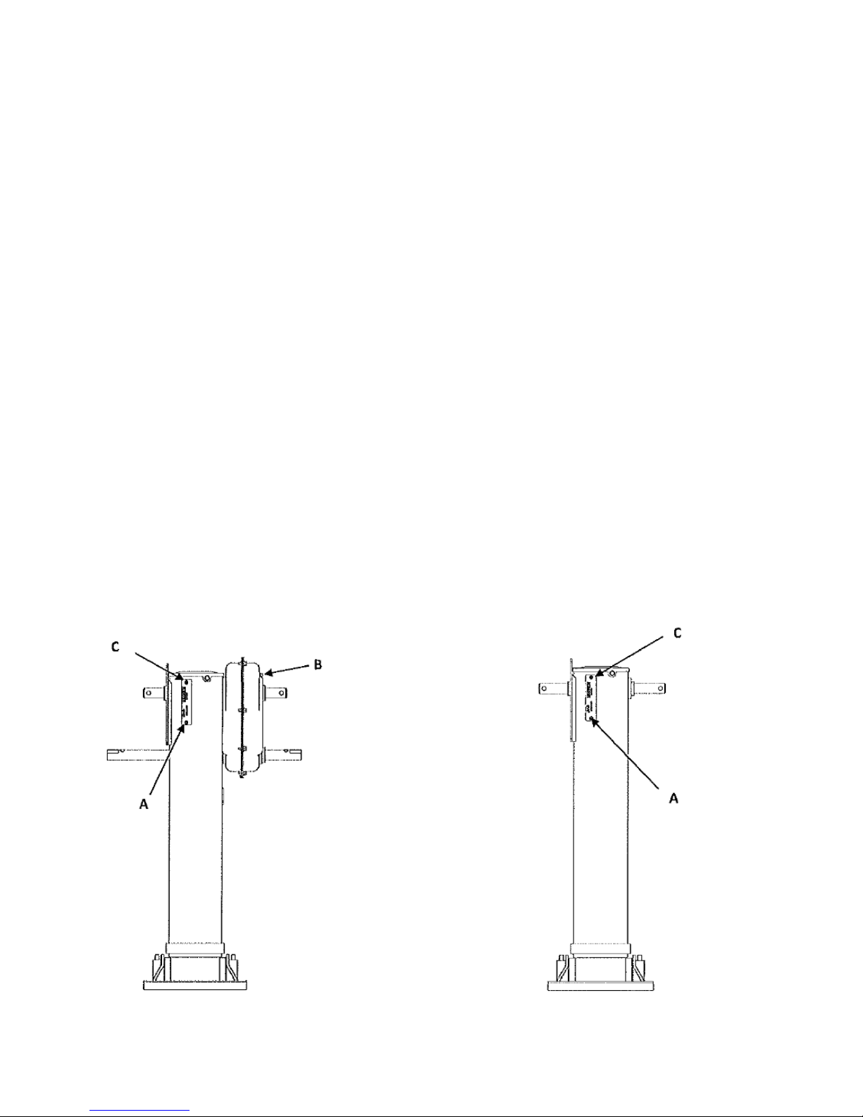
LANDING LEGS
LANDING GEAR LUBRICA TION IS IMPORTANT!
Your landing gear was adequately greased and packed with high quality lubricants when manufactured and will not require additional lubrication for the first five (5) year period of service and
operation. Following the initial five year period, it will be necessary to periodically supplement this
lubrication to maintain satisfactory performance for your particular application. Re-lubrication
should be part of your preventative maintenance program and should be done every month or
more often, if required.
For low temperature operations (under 20° F) use a lithium or an anhydrous calcium extreme
pressure grease that operates down to -65°F.
For cold weather operations, it is also recommended to fill the gearbox approximately 3/4 full with
grease. This helps minimize moisture accumulation, which can freeze, causing hard gear cranking.
For moderate temperature operations (20° F to 150° F) use a lithium or an anhydrous calcium
extreme pressure grease.
Lubricate as follows: (see FIGURE 1)
1. Fully retract the landing gear, then using high gear , lower the leg 2-3 turns and lubricate
the lift-screw assembly through grease fitting “A” (see landing gear legs shown below).
Apply ½ lb. of grease.
Distribute the lubrication by extending and retracting the leg several times.
2. Lubricate the gearbox, using grease fitting “B”. Apply ¼ lb. of grease
3. Lubricate the bevel gear using grease fitting “C”.
Apply ¼ lb. of grease.
Date of Origin – 02/01/08
FIGURE 1
60
Page 61

REPORTING SAFETY DEFECTS & OTHER CLAIMS
If you believe that this vehicle contains a safety defect you may contact T impte Trailer Company,
the National Highway T raffic Safety Administration (NHTSA) or both.
If you believe that this vehicle contains a safety defect you may contact T impte Trailer Company,
the National Highway T raffic Safety Administration (NHTSA) or both.
The trailer was designed and inspected to conform to industry standards and all applicable
NHTSA safety standards. Timpte T railer Co. warrants this vehicle to be free from defects in
materials and workmanship when manufactured per the limited warranty agreement. If you detect
a defect that could cause an accident or could cause an injury or death; or if you wish to report any
such accident, injury or death, or any property damage claim or other complaint not addressed to
the Timpte Trailer Warranty Dep artment, then you should contact in writing:
Timpte T railer Co.
Vice President of Engineering
1827 Industrial Drive
David City , NE 68632
Phone: 402-367-3056
Fax: 402-367-4340
If you believe that your vehicle has a defect which could cause a crash or could cause injury or
death, you should immediately inform the National Highway Traf fic Safety Administration (NHTSA)
in addition to notifying Timpte Trailer Co.
If NHTSA receives similar complaints, it may open an investigation, and if it finds that a safety
defect exists in a group of vehicles, it may order a recall and remedy campaign. However , NHTSA
cannot become involved in individual problems between you, your dealer, or Timpte T railer Co.
T o contact NHTSA, you may call the V ehicle Safety Hotline toll-free at 1-888-327-4236 (TTY : 1800-424-9153); go to http://nhtsa.safercar.gov; or write to: Administrator , NHTSA, 1200 New
Jersey Avenue SE, Washington, DC 20590. You can also obtain other information about motor
vehicle safety from http://www.safercar.gov
61
Date of Origin – 02/01/08
Page 62
MAINTENANCE SCHEDULE - HOPPER
Trailer Serial Number
Responsible Facility
Customer Name
Operations Manual to Customer Yes No
In-Service Date
Date Returned
Date of Inspection
Service Manager Signature
* Alignment and Suspension check *
1) Initial alignment check (30 days for Spring-Ride & 90 dates for Air-Ride)
2) Suspension Torque Requirements (see decals on trailer or maintenance manual for specific suspension)
Spring Ride - First 1000 miles - every 4 months periodically afterwards.
Air-Ride - First 3 months or 5,000 miles - Every routine p.m. - Every brake realigning
3) Check suspension for damage (cracks, loose or missing fasteners)
4) Check air-ride suspensions for conditions of bushings, air leaks and shock absorbers
5) Check spring condition for free movement of equalizer, condition of bushings, torque of fasteners
and any type of cracking or damage to the spring leafs.
* Wheels, Rims, Tires *
1) Check all wheel nuts for tightness and should be torqued to 450 to 500 ft-lbs (dry)
after 50 to 100 miles of service - weekly thereafter.
Check tires for cuts and abrasions.
2) Check tire inflation daily.
3) Check wheel stud condition for stripped & damaged threads (if damaged see owners manual)
Reference Manual for:
* vendor maintenance information concerning loading, inflation-maintenance procedures
* replacing damaged components, part number and type.
* Lights, Reflective Devices, Brakes and Electrical controls *
1) Check and clean all lamps, reflectors and conspicuity tape.
2) Check 7-way electrical connection.
3) Check air brake glad hands for cracked housing and for rubber washer damage.
4) Check air hoses and air lines for cracking and chafing.
5) Check the operation of brakes. Check stroke indicators on auto slacks for proper adjustment.
6) Drain moisture from the air brake system by opening the drain cocks on air tanks.
7) Check ABS warning lamp for system status.
* FIFTH WHEEL AND KING PIN *
1) Inspect king pin and its structure on the trailer for damage or unusual wear.
2) Inspect coupling for positive engagement of the fifth wheel and king pin.
3) Inspect for proper lubrication of 5th wheel plate.
* Trailer Body and Structural Components *
1) Visually check trailer body, suspension, sub-frame, upper coupler, etc. for any cracking,
deterioration or of any loose or missing fasteners.
2) Check trailer sides for damage, sharp bends, ripples or missing fasteners.
DAILY
WEEKLY
MONTHLY
ANNUALLY
SEMI-ANNUAL
QUARTERLY
MILEAGE/HR
Actual Reading Time Spec Date Initials
MILEAGE/HR
DAILY
DAILY
DAILY
DAILY
DAILY
DAILY
DAILY
DAILY
DAILY
DAILY
DAILY
DAILY
DAILY
DAILY
DAILY
WEEKLY
DAILY
DAILY
* Tarp System *
1) Check to be sure the tarp is in serviceable condition.
2) Insure that the latching system is in good working order.
3) Check proper operation of electric tar p system if on trailer.
Reference Manual for:
*securing tarp prior to travel to prevent damage.
* In-Line Filter *
1) Inspect and clean
* Lubrication *
1) Hub Oil - Check Daily - Change every 100,000 miles (every year minimum)
2) Trap operator U-Joints
3) Auto slacks
4) Cam Bushings (4 times during the life of brake linings - 25,000 miles)
Control Document: 011-46246
Origination Date: 9/11/2011
Date of Origin – 02/01/08
DAILY
DAILY
DAILY
QUARTERLY
DAILY
MONTHLY
SEMI-ANNUAL
MILEAGE/HR
62
Page 63

IMPORTANT - READ THIS
Timpte Reference Guide
Thank you for purchasing a new T impte T railer. If you are a first time purchaser or a long time customer this
guide is a starting point to better understanding of your T impte T railer .
• Inspect your trailer to ensure that all is correct and complete as ordered. Go over Final Quality Control
Check list with release agent or sales agent.
• Trailer packet – This packet cont ains information regarding specific components of your trailer .
• Maintenance Schedule – Please refer to the maintenance schedule in the trailer packet. This document
contains important information about maintenance, lubrication and torque requirements. Some highlights:
a. Alignments – Complimentary if done within 30 days for spring ride, 90 days for air ride. Call
Warranty Department for details (402-367-3056).
b. Check wheel torque within the first 50 to 100 miles (450 to 500 ft-lbs dry).
c. Suspension Torque Requirements (see decals on trailer or maintenance manual for specific
suspensions).
d. Several Daily inspections are required of all operators. Refer to the Operators Manual for
details (page 55).
e. Lubrication (Refer to Operators manual page 55).
1. Check hub oil daily (change every 100,000 miles).
2. Lubricate trap operator U-joints monthly .
3. Lubricate auto slacks and Cam bushings every 25,000 miles or semi-annually.
4. If so equipped ensure that vibrators are getting properly lubricated and oil reservoir is filled.
If not equipped with auto oiler, vibrators must be oiled prior to each use.
• Inspect and clean In-Line Filter on nose quarterly (refer to Wabco Manual in trailer packet).
• Keep ratchet and pawl lock adjusted properly (refer to Operators Manual for procedure page 16).
• Warranty – The T impte W arranty Department will need to be contacted in advance for warranty rep airs
and a claim number issued for such repairs that are warrantable (402-367-3056).
Serving the transportation industry since 1884.
63
Date of Origin – 02/01/08
Page 64

TIMPTE “PEACE OF MIND” LIMITED WARRANTY
(FOR TRAILERS BUILT ON OR AFTER FEBRUAR Y 16TH, 2011)
Subject to the following paragraphs and warranty schedule, T impte, Inc. warrants the First Purchaser* from Timpte, or from an authorized Timpte dealer , that a new bulk commodities trailer
manufactured by Timpte, used in Normal Service**, will be free from defect s in materials and
workmanship for the period of three years from the date of
delivery to the First Purchaser* except as listed in the exceptions below.
Axle Alignments
Timpte will pay reasonable and customary charges*** for a standard inspection of the trailer
alignment and readjustment of the alignment
Spring Ride Suspension Trailers – 30 days
Air Ride Suspension Trailers – 90 days
Tires- T impte provides no warranty coverage on the tires. They are
covered under a separate manufacturer’s warranty .
ear Coverage
1 Y
• Tarps
• Coating on steel parts
• Wheel Seals
• Pneumatic Vibrators
5 Year Coverage
• Landing Legs
• Axles
• Wheels
• Two Speed Gear Boxes
• Spring Ride Suspension Components
• Hub & Drum
• Auto Slack Brake Adjusters
This warranty does not cover items that need periodic adjustment as part of normal maintenance
such as but not limited to; trap door adjustment and wheel bearing end play adjustment. This warranty does not cover any goods which are not defective, but which wear out and have to be replaced
during the warranty period, including for example, but not limited to tires, lamps, lamp bulbs, brake
linings, brake drums, suspension bushings, lubricants, wheel flaps, tarps, seals, grommet mountings,
wire ties, circuit breakers, and the like.
Timpte reserves the right to change or clarify the warranty coverage at any time. Contact the T impte
Warranty Administration Group at 402-367-3056 for any specific questions on coverage.
Date of Origin – 02/01/08
64
Page 65

WARRANTY EXCLUSIONS
Misuse, neglect, overloading, improper loading, failure to follow any recommended
loading or operating instructions, failure to follow specified maintenance procedures and intervals,
unauthorized repair or structural modifications or failure to provide normal
maintenance shall void this warranty in its entirety .
This warranty does not cover purchased components, attachments, or accessories, whether
acquired from or provided by a Timpte dealer, T impte branch, or any other party, that are not in
accordance with the factory-level standard specifications.
All warranty work must be approved by the Timpte Warranty Department prior to any
work being performed.
CUSTOMER RESPONSIBILITIES
First Purchaser* shall regularly inspect and check the trailer and follow all recommended
The
maintenance procedures and intervals.
First Purchaser* shall contact the Timpte Trailer Warranty Department immediately at 402-
The
367-3056 upon detection of any perceived defect in the materials or workmanship. Any continued
use of the trailer after discovery of a defect that could in any way aggravate the defect or otherwise
damage the trailer will void the warranty on that part of the trailer .
Absolutely no work should be performed to the trailer prior to receiving authorization as
evidenced by a valid claim number, from the Timpte Warranty department. Any work
performed prior to receiving authorization will not be covered under warranty.
The First Purchaser* shall comply with the instructions of the W arranty Department related to a
claim within 30 days of the date of those instructions or the warranty on that part of the trailer is
voided. The T impte Warranty Department will issue a claim number as authorization for approved
warranty repair . T impte will not pay for any warranty work that was performed without a valid claim
number. All transportation charges in connection with a warranty claim will be the sole responsibility of the First Purchaser*.
The First Purchaser’s* sole and exclusive remedy against T impte, arising from the purchase and
use of the trailer, is limited to rep air or replacement of defective materials and workmanship, as
provided herein.
65
Date of Origin – 02/01/08
Page 66

TIMPTE MA Y AT ITS OPTION REQUIRE THA T THE DEFECTIVE P ART OR TRAILER BE
RETURNED TO A TIMPTE FACILITY OR A TIMPTE AUTHORIZED SERVICE SHOP , AS
TIMPTE MA Y DETERMINE.
ALL W ARRANTY WORK MUST BE PERFORMED A T THE LOCA TION DESIGNA TED OR
APPROVED IN ADV ANCE BY TIMPTE AND TO THE SPECIFICA TIONS DICTA TED BY
TIMPTE.
* “First Purchaser” means the first purchaser in good faith for a purpose other than resale.
** “Normal Service” means the loading and transportation of uniformly distributed legal loads of properly
secured, noncorrosive cargo, in accordance with any applicable factory instructions and in a manner
which does not subject the trailer or parts of the trailer to (a) concentrated loads; (b) loads in excess of the
Gross Axle Weight Rating (GAWR) or Gross Vehicle W eight Rating (GVWR) st ated on the Certification Plate
affixed to the trailer by Timpte; and (c) accidental damage, impact or shock greater than those commensurate with normal, reasonable, lawful use.
*** “Normal and Customary Charges” are a sum not exceeding the price charged by Timpte for such work.
LIABILITY LIMITATIONS
TIMPTE SHALL NOT BE LIABLE TO THE FIRST PURCHASER* OR ANY
OTHER PERSON FOR ANY DAMAGES, DIRECT, INCIDENTAL, CONSEQUENTIAL, PUNITIVE OR OTHERWISE FOR BREACH OF WARRANTY,
FAILURE OR DELAY IN MAKING DELIVERY, OR ANY OTHER CAUSE,
EXCEPT AS SPECIFICALLY SET FORTH IN THIS WARRANTY. IN NO
EVENT WILL TIMPTE'S CUMULATIVE LIABILITY FOR BREACH OF THIS
WARRANTY EXCEED THE PRICE CHARGED BY TIMPTE FOR ANY PART
TO BE REPLACED PLUS NORMAL AND CUSTOMARY CHARGES ***FOR
REPAIRS TO BE MADE UNDER THIS WARRANTY.
WITHOUT LIMITING THE FOREGOING, TIMPTE SHALL NOT BE LIABLE
FOR ANY DAMAGES WHATSOEVER AS A RESULT OF CARGO LOSS,
DOWNTIME, DRIVER, ROAD SERVICE, TOWING EXPENSE, TIRE REPAIR
SERVICE, LOSS OF PROFIT, RENTAL OR SUBSTITUTE EQUIPMENT OR
ANY OTHER TYPE OF LOSS DUE TO TRAILER PERFORMANCE. PREMIUM LABOR RATES (I.E. OVERTIME, SERVICE CALLS, ROAD SIDE/
MOBILE SERVICE) WILL NOT BE PAID FOR WARRANTY REPAIRS.
THE WARRANTIES SET FORTH HEREIN ARE THE ONLY WARRANTIES
APPLICABLE TO TIMPTE BULK COMMODITIES TRAILERS AND ARE
EXPRESSLY IN LIEU OF ALL OTHER WARRANTIES, EITHER EXPRESSED
OR IMPLIED, INCLUDING, BUT NOT LIMITED TO, IMPLIED WARRANTIES
OF MERCHANTABILITY AND FITNESS FOR A PARTICULAR PURPOSE.
Date of Origin – 02/01/08
66
Page 67

TIMPTE’S OBLIGATION
In the event of a defect in material or workmanship covered by this warranty,
Timpte Inc. in its sole discretion will:
• Correct the defective work or replace the defective parts at Timpte’s factory
or at a Timpte Branch or dealer assigned by Timpte.
• Or reimburse the First Purchaser* by paying a sum not exceeding the price
charged by Timpte for such work or part,
• Or provide for repair of the defective parts by an authorized Timpte service
facility,
• Or supply a replacement part to the First Purchaser*, who will install it at
his own expense.
To file a claim or if you have any questions concerning this warranty, contact the
Timpte Warranty Department at:
Timpte, Inc.
1827 Industrial Drive
David City, NE 68632
402-367-3056
4848-8465-0248, v. 1
67
Date of Origin – 02/01/08
Page 68

(Last six of the VIN#)
Timpte operates five service and parts centers:
Timpte T railer Co.
2801 23rd A venue
Council Bluffs, IA 51501
Phone#800-654-0636
Timpte T railer Co.
5368 Hutton Drive
Urbana, IA 52345
Phone#866-865-0992
Timpte T railer Co.
2225 Howard Drive West
North Mankato, MN 56003
Phone#800-334-2096
Timpte T railer Co.
160 West Progress Drive
Princeton, IL 61356
Phone#866-875-6509
Timpte T railer Co.
th
3416 South 16
St.
Aurora, NE 68818
Phone#888-256-4884
Date of Origin – 02/01/08
68
Page 69

FCC&IC Caution:
This device complies with Part 15 of the FCC Rules and Canada
licence-exempt RSS-210 standard. Operation is subject to the following two
conditions:
OPERATIONS IS SUBJECT TO THE FOLLOWING TWO CONDITIONS:
(1) THIS DEVICE MAY NOT CAUSE HARMFUL INTERFERENCE
(2) THIS DEVICE MUST ACCEPT ANY INTERFERENCE RECEIVED,
INCLUDING INTERFEERENCE THAT MAY UNDESIRED OPERATION.
 Loading...