

Page 1
H. Timm Elektronik GmbH | Humboldtstr. 29 | 21509 Glinde | GERMANY
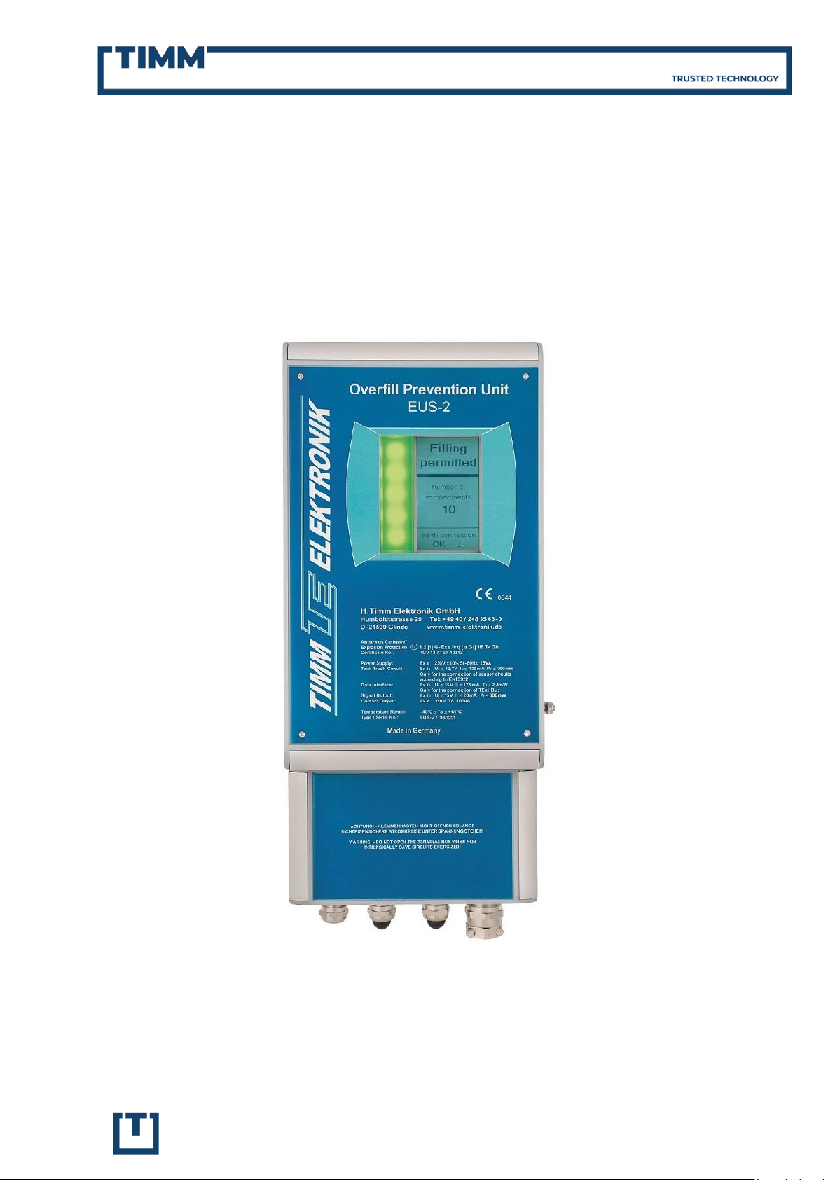
OVERFILL PREVENTION CONTROLLER EUS-2
Technical Description | Version 1.81 | English
Page 2
H. Timm Elektronik GmbH | Humboldtstr. 29 | 21509 Glinde | GERMANY
Table of Content
1. General Information ............................................................................................................................................... 1
2. Functional Principle ............................................................................................................................................... 1
3. Special Features ....................................................................................................................................................... 2
3.1. Compliance to latest European and American Standards ................................................... 2
3.2. Intelligent Explosion Protection .............................................................................................................. 2
3.3. High Functional Safety | Fail Behavior .............................................................................................. 2
3.4. Bright Signal Light ............................................................................................................................................ 2
3.5. Graphic Display .................................................................................................................................................... 2
3.6. Easy Configuration by Joystick ................................................................................................................ 3
3.7. Reliable Ground Verification ...................................................................................................................... 3
3.8. Control Outputs | Data Interface ............................................................................................................ 3
3.9. Extended Area of Application ................................................................................................................... 3
4. Accessories .................................................................................................................................................................. 4
4.1. Coiled Cable ........................................................................................................................................................... 4
4.2. Disconnector Socket ........................................................................................................................................ 4
4.3. Testing Equipment ........................................................................................................................................... 5
5. Technical Specifications ..................................................................................................................................... 6
6. Connection Diagram ............................................................................................................................................. 7
8. International Approvals ...................................................................................................................................... 8
9. Contact us ...................................................................................................................................................................... 1
Page 3

13.03.2019 | V1.81
1 | 9
Overfill Prevention Controller EUS-2 | Technical Description
info@timm-technology.de
www.timm-technology.de
Figure 1: Bottom loading with overfill prevention control by Timm`s control unit type EUS-2
1. General Information
As stationary part of the Overfill Prevention System for liquid fuels, the explosionproof control unit type EUS-2 complies
with the requirements on overfill prevention systems for bottom-loading tank
trucks according to Annex IV of VOC-Directive 94/63/EC as well as with European
standard EN 13922 and American API RP
1004 recommendations. Timm has combined its longterm competencies in explosion protection and experiences in
overfill prevention in this control unit.
EUS-2 is characterised by ease of installation, convenient operation, functional
safety and a user-friendly state-of-the-art
explosion protection concept (IEPC) designed by Timm.
2. Functional Principle
To ensure a safe filling process, the overfill
prevention controller EUS-2 provides
three main functions:
Overfill prevention
Grounding verification
Vapour recovery monitoring
During loading of tank trucks, the level
sensors at the truck (one sensor per tank
compartment) are connected to the control unit at the filling gantry by a standard
plug and socket connection. The level
sensors are positioned in the top of each
tank compartment deep enough to assure that once a sensor gets activated,
product flow stops before the compartment is completely full. In case a sensor
senses liquid, the control unit triggers to
shut-off the product flow for all compartments to prevent leakage of fuel or the
compartment’s bursting.
When being connected to a tank truck,
the control unit EUS-2 detects the type of
level sensors (optic/thermistor), the sensor installation (five-wire/two-wire) as well
as the way of ground verification (resistance/ ground bolt) and activates automatically the required operating mode.
For a wide range of applications, tank
trucks with up to twelve five-wire sensors
and eight two-wire sensors are supported.
The control unit verifies permanently the
correct grounding of the truck via the
connection cable. The preset limit value of
this verification can be set according to individual requirements exceeding EN
13922 requirements.
The vapour recovery hose connection is
monitored on the tank truck via an electro-pneumatic interlock switch, which is
looped into the grounding verification
line. The control unit EUS-2 ensures that
filling is only possible if the vapour recovery system and the grounding line are
connected properly.
Page 4
13.03.2019 | V1.81
2 | 9
Overfill Prevention Controller EUS-2 | Technical Description
info@timm-technology.de
www.timm-technology.de
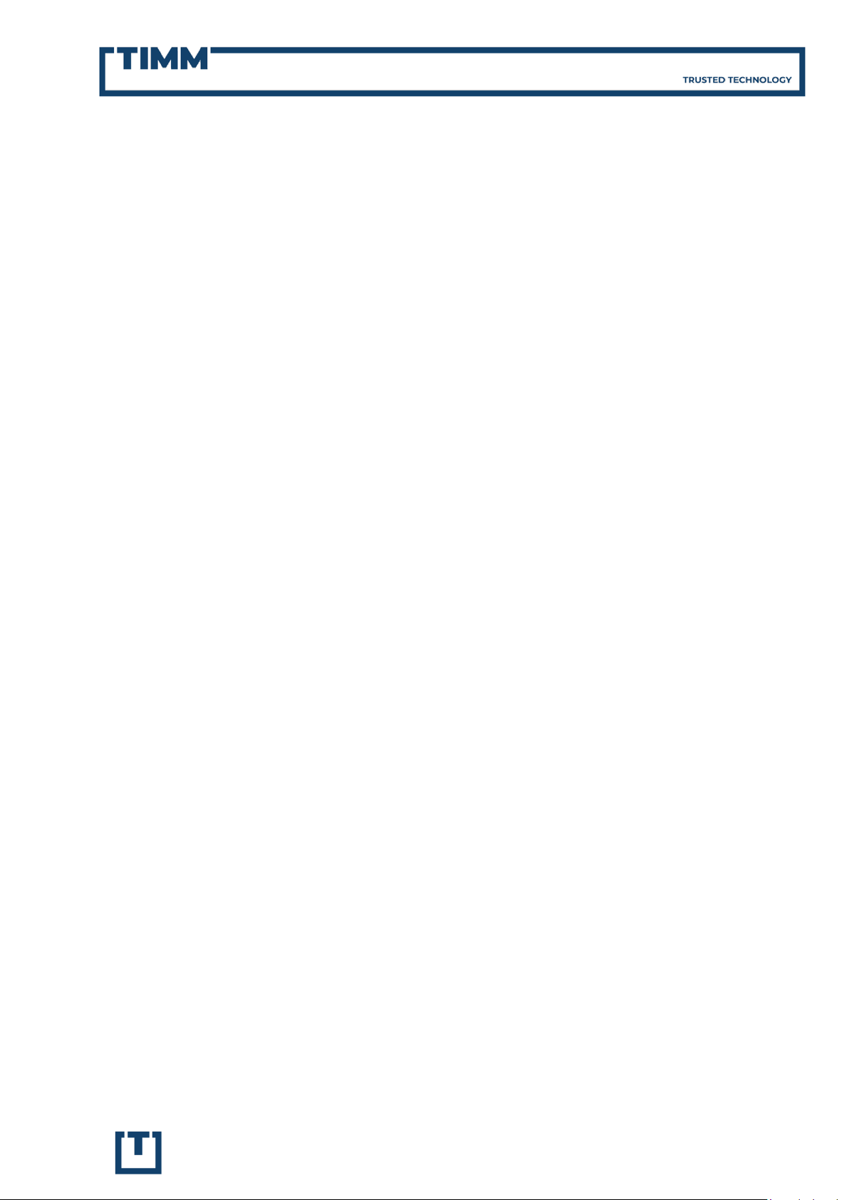
Figure 2: Opening of enclosure in hazardous
areas for easy configuration
LED signal light indicates main status
Graphic display for
plaintext messages
3. Special Features
3.1. Compliance to latest European
and American Standards
The EUS-2 control unit is designed in full
compliance to the newest editions of European ATEX and EMC Standards, European Standard on Overfill Prevention EN
13922 as well as to American Guideline API
RP 1004. With Timm Elektronik being an
independent manufacturer, full compatibility to corresponding truck equipment
and level sensors of other manufacturers
is ensured for operation worldwide. The
control unit EUS-2 is capable to detect automatically the type of counterpart truck
equipment and activates the required operating mode. With the offered disconnector sockets, cables with plugs for the
different receptacles can easily be exchanged or even connected to the controller at once.
3.3. High Functional Safety |
Fail Behavior
All safety related functions, internal components and the external wiring are monitored continuously by the device itself.
Filling release is permitted only if periodic
self-testing operates properly.
3.4. Bright Signal Light
The EUS-2 unit is equipped with a clearly
visible bright multi-colour LED signal
light. With its bevelled edges, the light is
visible in a wide angle. This leads to unambiguous indication of operational status
and time efficient utilisation at filling station.
3.2. Intelligent Explosion Protection
TIMM`s intelligent explosion protection
concept (IEPC) combines protection by
intrinsic safety, increased safety, powder
filling and protection by enclosure. With
this unique combination of the types of
protection, the main housing can be
opened in gas hazardous areas when
power is switched on for configuration
and service (e.g. for setting the additional
control outputs or the display language).
3.5. Graphic Display
The large graphic display indicates clearly
visible the actual operating status and
auto-diagnosis information as plaintext
messages. In combination with the joystick control, a simple, menu-driven and
self-explaining configuration of the control unit and easy failure analysis is provided. Several character-sets are available
for different languages.
Page 5

13.03.2019 | V1.81
3 | 9
Overfill Prevention Controller EUS-2 | Technical Description
info@timm-technology.de
www.timm-technology.de
Figure 3: Joystick for menu-driven device
configuration
3.6. Easy Configuration by Joystick
For easy configuration at the installation
site (e.g. of the configurable control outputs K3, K4 and E2), the EUS-2 unit features a unique joystick control. It is situated well accessible on the backside of
the front cover inside the units housing
and allows an intuitively configuration
with concurrent view to the graphic display.
3.8. Control Outputs | Data Interface
Six control outputs enable advanced options for connecting the control unit according to individual customer needs:
2 Contact Release Outputs
(redundant, potential-free,
intern monitored)
1 Electronic Release Output
2 Configurable Contact Outputs
1 Configurable Electronic Output
The serial data communication interface
eases process integration. Operational
state commands can be transmitted to
external process control systems. This allows remote diagnosis and process visualisation.
The analysis of the different control signals enables to distinguish, whether a filling process got interrupted by a correctable error (e.g. missing vapour recovery
hose connection) or an actual overfilling.
3.7. Reliable Ground Verification
The EUS-2 unit features continuously
grounding verification and the ability for
setting the grounding limit value exceeding EN 13922 requirements. Grounding is
monitored reliable independent from
truck configuration:
Trucks with grounding lines di-
rectly connected to the chassis
(EN 13922)
Trucks with grounding verification
via recognition device
(‘ground bolt’)
With a strict grounding limit value, wearing off or dirt at the plug and socket
connection will be noticed in time for preventive measures.
3.9. Extended Area of Application
The type of explosion protection makes
the control unit applicable to Gas Group
IIB for filling even pure Ethanol. Furthermore, with its extended temperature
range from -40 °C up to +60 °C, the device
provides reliable operation under extreme
climate conditions.
Page 6

13.03.2019 | V1.81
4 | 9
Overfill Prevention Controller EUS-2 | Technical Description
info@timm-technology.de
www.timm-technology.de
Truck connector
plug
Disconnector
plug
Figure 4: Coiled cable with disconnector plug
Disconnector plug
fort ruck connector
plug
Disconnector socket
with bolt handles for
truck cables with disconnector plug
Figure 5: Disconnector socket junction box
EUS-1-STP
4. Accessories
TIMM provides a variety of accessories for
its Overfill Prevention Controller.
4.1. Coiled Cable
The coiled cables come in two lengths,
with truck connector plugs according to
EN 13922 or API RP 1004 as well as with or
without disconnector plug.
EUS-1-SK7: blue PUR coiled cable
with truck connector plug, cable
length about 2.6 m, expandable to
about 7.5 m for direct connection
to the control unit.
EUS-1-SSK7: as type above-men-
tioned, but with additional disconnector plug for detachable connection to disconnector socket
junction box EUS-1-ST or EUS-1STP.
EUS-1-SSK3: as type above-men-
tioned, but in short length of about
1.5 m, expandable to about 3.5 m;
particularly intended for use with
disconnector socket junction box
type EUS-1-STG11/11P at loading
arm
Available truck connector plugs mounted
to the coiled cables:
Black 10-pole plug with four lock-
ing pins and ten electrical contacts, according to EN 13922 (for
thermistor type and optic type vehicle sensor systems).
Blue marked plug with three lock-
ing pins and seven electrical contacts (fitting onto 6-pin truck sock-
ets for optic vehicle sensor systems
acc. to API RP 1004 standard). The
additional 7th pin is intended for
identifying the parking socket.
4.2. Disconnector Socket
The following intrinsically safe disconnector socket junction boxes are available:
For installation at filling gantry:
EUS-1-ST: junction box with dis-
connector socket to connect a
plug-in coiled cable type EUS-1SSK7 or EUS-1-SSK3; complete with
1 m uncoiled cable for connection
to the control unit.
EUS-1-STP: as type above-men-
tioned, but with additional codegenerating truck socket for de-
tecting the ‘truck connector in
park position’ status.
EUS-1-ST2P2: dual junction box
with two disconnector sockets for
the detachable connection of two
coiled cables with different truck
connector plugs to the controller;
including two park position sockets.
Electrical contacts of the plug are used as
well for detecting the park position in
combination with suitable parking sockets.
Page 7

13.03.2019 | V1.81
5 | 9
Overfill Prevention Controller EUS-2 | Technical Description
info@timm-technology.de
www.timm-technology.de
Figure 6: Dual disconnector junction box
EUS-1-ST2P2
Figure 7: Disconnector socket unit
Figure 8: Testing Equipment EUS-TST3
4.3. Testing Equipment
The functioning of the control unit can
easily get checked by using the special
testing equipment. It is equipped with a
socket for connecting to the truck connector cable as well as with different testing switches to simulate the criteria
‘grounding’, ‘vapour recovery hose connection’ and individual ‘sensor status’.
The testing equipment is available with
sockets according to EN 13922 or API RP
1004.
For installation at the vapour recovery
arm (close to coupling):
EUS-1-STG11: disconnector socket
unit to connect a plug-in coiled cable type EUS-1-SSK3. With 11 m
straight cable to the control unit
and a cable mounting set for cable
installation at the vapour recovery
arm.
EUS-1-STG11P: same as type above-
mentioned, but with additional
truck socket for detecting the
‘truck connector in park position’
status by integrated socket code
generator.
Page 8

13.03.2019 | V1.81
6 | 9
Overfill Prevention Controller EUS-2 | Technical Description
info@timm-technology.de
www.timm-technology.de
5. Technical Specifications
5.1. Operating Data
Device category according to ATEX
(directive 2014/34/EU)
II 2 [1] G
Type of protection
Ex eb ib q [ia Ga] IIB T4 Gb
Protection of enclosure
IP66
Shut down response time
≤ 450 ms
Power Supply
Type of protection ‘increased safety’
Ex eb
230 V AC ± 10 %, 50-60 Hz,
about. 25 VA
Ambient temperature range
-40 °C to +60 °C
Dimensions
475 mm, 215 mm, 120 mm (H, W, D)
Weight
about 10 kg
5.3. Control Output Circuits
Contact Outputs
Type of protection “Increased safety”
Ex eb
Maximum values: 250 V AC, 3 A, 100 VA
2 Filling release Contacts
redundant, potential-free, intern
monitored, closing contacts
2 Additional Contacts
Potential-free changeover contacts,
configurable for detailed signalling
‘grounding’, ‘overfilling’, ‘filling process’, ‘parking position’
Electronic Output (E1, E2)
Type of protection “Intrinsic safety”
Ex ib
NAMUR-compatible
For connection to certified intrinsi-
cally safe circuits
Maximum values
Ui ≤ 15 V, Ii = 20 mA, Pi = 300 mW
Electronic Filling Release Output
potential-free, oscillating (fail-safe)
Additional Electronic Output
potential-free, optionally switchable
static or oscillating
5.2. Sensor and Grounding Circuits
Type of Protection
“intrinsic safety” Ex ia
For connection to apposite level sen-
sors
Maximum 8 two-wire-sensors or
Maximum 12 five-wire-sensors
Cable length
Maximum 50 m (Ex specification,
functional limitations must be observed)
Maximum values
Uo = 12,7 V, Io = 129 mA,
Po = 360 mW
Serial Data Interface
Type of protection: ‘Intrinsic Safety’
Ex ib
For connection to TExi-Bus (Timm
intrinsic safety databus)
Maximum values: Ui ≤ 15 V, Ii ≤ 175
mA, Pi ≤ 2,4 W
Page 9

13.03.2019 | V1.81
7 | 9
Overfill Prevention Controller EUS-2 | Technical Description
info@timm-technology.de
www.timm-technology.de
L1, N, PE: Power supply
1 - 2: Closing contact output K1 - Filling release
3 - 4: Closing contact output K2 - Filling release
5 - 7: Switching contact output K3 - Configurable
8 - 10: Switching contact output K4 - Configurable
15 - 16: Ex i Electronic output E1 - Filling release
17 - 18: Ex i Electronic output E2 - Configurable
11 - 14: Ex i Data-interface (TExi-Bus)
19 - 28: Tank truck cable connection
6. Connection Diagram
Page 10

13.03.2019 | V1.81
8 | 9
Overfill Prevention Controller EUS-2 | Technical Description
info@timm-technology.de
www.timm-technology.de
Europe (EU + EFTA)
EC-Type-Examination Certificate
TÜV 13 ATEX 132121
to TR ZU 012/2011
8. International Approvals
In addition to the ATEX certificate, we also have Ex-approvals for the EUS-2 according to
IECEx and EAC Ex (according to TR-CU 012/2011) for Australia, Oceania and the Eurasian cus-
toms union.
Australia | Oceania
IECEx Certificate
Russia / EAEU
EAC Ex Certificate according
Page 11

13.03.2019 | V1.81
1 | 9
Overfill Prevention Controller EUS-2 | Technical Description
info@timm-technology.de
www.timm-technology.de
Dr. Alexander Zelck
Head of international sales
Inga Klemmer
Dipl.-Ing. Andreas Brückner
9. Contact us
If you would like to contact us regarding offers and sales or technical support, our
employees will be glad to be available for you on the following contact information.
+49 40 248 35 63 - 31
zelck@timm-technology.de
klemmer@timm-technology.de
Sales &
order processing
+49 40 248 35 63 - 33
Technical support &
quality management
+49 40 248 35 63 - 35
brueckner@timm-technology.de
 Loading...