

Page 1
Installation Guide
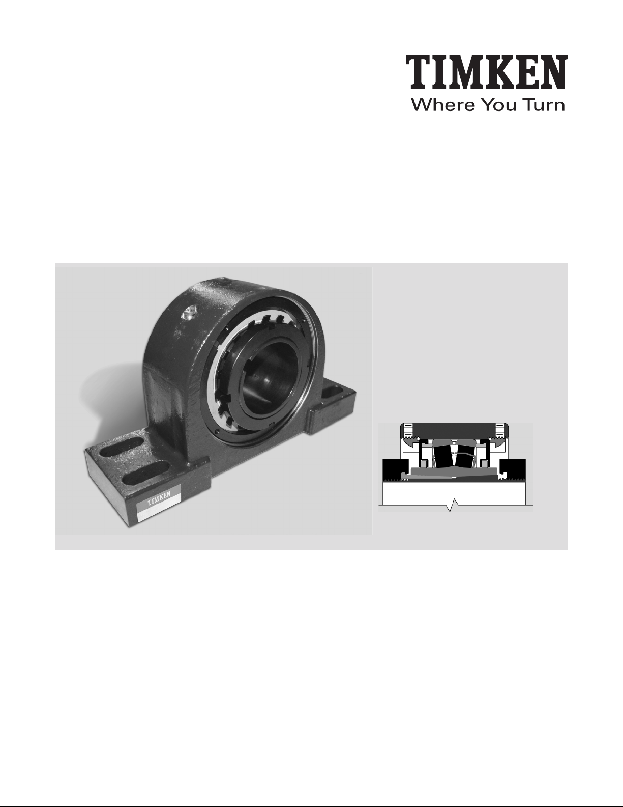
Timken® Spherical Roller Bearing Solid-Block Housed Unit
V-Lock Series
Page 2
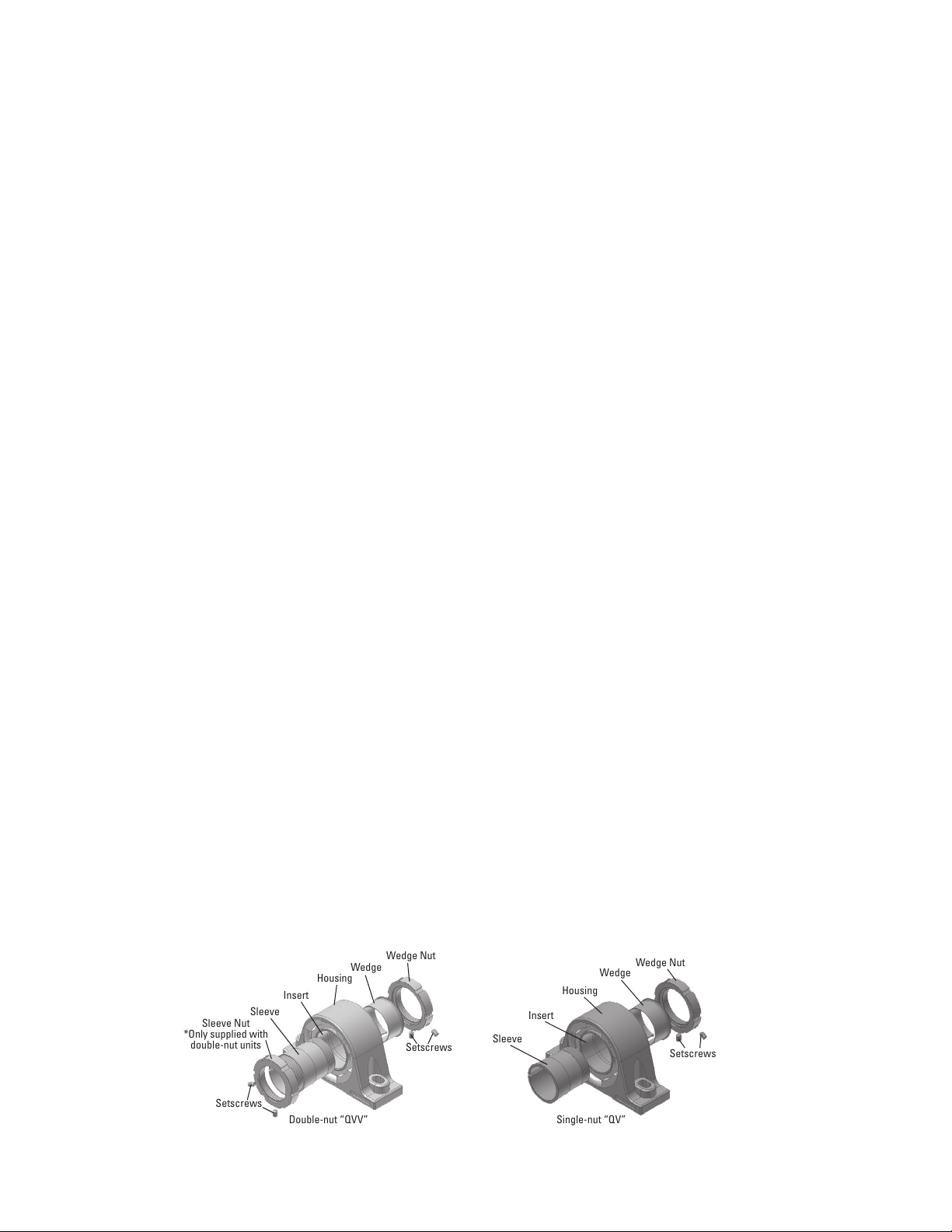
Wedge Nut
Wedge
Housing
Insert
Sleeve
Sleeve Nut
*Only supplied with
double-nut units
Setscrews
Double-nut “QVV” Single-nut “QV”
Setscrews
Wedge Nut
Wedge
Housing
Insert
Sleeve
Setscrews
INSTALLATION GUIDE
V-LOCK SERIES, SPHERICAL ROLLER BEARING SOLID-BLOCK HOUSED UNIT
Timken solid-block housed unit V-Lock bearings are easy to install and remove
because of their unique adapters.
Please complete the following steps to install and/or remove Timken steel housed
unit V-Lock bearings. (Refer to fig. 1.)
INSTALLATION
1. Ensure that the shaft is clean, free from nicks and burrs, straight and
of proper diameter. See table 1 for recommended shaft tolerances.
The housed unit should not be mounted on a worn section of the shaft.
Use of shafts with hardness greater than Rc 45 will reduce the
effectiveness of locking devices.
2. If using an open-end cover, slide the open-end cover/seal combination
into position on shaft.
3. Remove the wedge assembly from the sleeve by unscrewing the wedge
nut. See fig. 1.
4. Clean oil off of the sleeve and wedge.
5. Apply a thin oil film to the shaft only.
For QV housed units:
- Slide the sleeve, non-threaded end first, into position on shaft.
For QVV housed units:
- Make sure the sleeve nut is flush with the end of the sleeve.
- Slide the sleeve/nut assembly, nut end first, into position on the shaft.
6. Slide the housed unit into place over the sleeve.
7. Loosely install the housed unit mounting bolts. Check the housed unit
alignment (fig. 2). Verify mounting surfaces are in the same flat plane to
help make sure good alignment is achieved. If shimming is required to
minimize misalignment, use full shims across entire housing base where
possible (fig. 2). Washers should be properly sized to bold diameter and
should not be an SAE grade, which is smaller.
- Seat the sleeve as best as possible into mounted unit.
8. Slide the wedge and wedge nut into the housed unit over the sleeve.
9. Tighten the wedge assembly by turning the wedge nut clockwise until tight.
Please note that it is designed to eliminate over-tightening.
10. If installing double-nut housed unit, tighten the sleeve assembly by turning
the sleeve nut clockwise until snug.
11. Tighten both the wedge nut and sleeve nut set screws alternately
according to table 2.
12. Install the housed unit mounting bolts. Check the housed unit alignment.
Verify mounting surfaces are in the same flat plane to help make sure good
alignment is achieved. If shimming is required to minimize misalignment,
use full shims across entire housing base
where possible (fig. 2). The bolts then need
to be alternately torqued securely to their
mounting supports.
13. Tighten the housed unit mounting bolts.
14. If using covers:
- Make sure the mating surface of cover and
retaining nut are clean and dry.
- If using a urethane cover, slightly roughen the
mating surface of the cover.
- Place a 1⁄8 in. - 1⁄4 in. bead of polyurethane
adhesive sealant on the mating surface of the
cover.
- Align cover mounting holes with the mounting
holes on the retaining housing nut (make
sure that the grease fitting on the cover is
accessible when doing so).
- Apply and tighten cover mounting hardware.
REMOVAL
1. Remove covers, if applicable, by removing
cover hardware and disengaging cover from
housed unit retaining nut.
2. Loosen the setscrews on the wedge nut.
3. Turn the wedge nut counterclockwise to
remove the wedge from the locked position.
4. Completely remove the wedge/wedge nut
assembly.
For QV housed units:
- Remove the bearing and sleeve from the shaft.
For QVV housed units:
- Loosen the setscrews on the sleeve nut.
- Turn the sleeve nut clockwise to un-seat the
sleeve.
- Remove the bearing and sleeve/sleeve nut
from the shaft.
Fig. 1. V-Lock insert components.
Page 3

TABLE 1. RECOMMENDED SHAFT TOLERANCES
TABLE 2. SETSCREW TORQUE VALUES
Shaft Size
in. mm
1 15⁄16
2
2 3⁄16
2 1⁄4
2 7⁄16
2 1⁄2
2 11⁄16
2 3⁄4
2 15⁄16
3
3 3⁄16
3 1⁄4
3 7⁄16
3 1⁄2
3 11⁄16
3 15⁄16
4
4 7⁄16
4 1⁄2
4 15⁄16
5
Bearing
Number
50 22211
55
60
65
70
75
80
85
90
22212
22213
22214
22215
22216
22217
22219
22220
100 22222
110
115
125
130
22226
22228
Tolerance
in.
mm
+0.000/-0.0015
+0.000/0.0381
+0.000/-0.002
+0.000/-0.0508
+0.000/-0.003
+0.000/-0.0762
+0.000/-0.005
+0.000/-0.127
Bearing Size Setscrew Size Torque
in. in.-lbs.
SLV11 TO SLV20
SLV22
SLV26 TO SLV28
washer
shim
3
⁄8 - 24TPI 290
7
⁄16 - 20TPI 420
1
⁄2 - 20TPI 620
Use washers and full shims.
Fig. 2.
washer
shim
TABLE 3. RE-LUBRICATION INTERVALS
Shaft Size
Bearing
Number
Weight
Initial
Relubri-
cation
Weight
100 RPM 250 RPM 500 RPM 1000 RPM 2000 RPM 3000 RPM
in. mm oz. oz. <160° F >160° F <160° F >160° F <160° F >160° F <160° F >160° F <160° F >160° F <160° F >160° F
1 15⁄16
2
2 3⁄16
2 1⁄4
2 7⁄16
2 1⁄2
2 11⁄16
2 3⁄4
2 15⁄16
3
3 3⁄16
3 1⁄4
3 7⁄16
3 1⁄2
50 22211 1 0.3 1200 600 800 400 440 220 160 80 100 50 60 30
22212 1.2 0.3 1150 580 750 380 400 200 140 70 90 50 50 20
55
22213 1.3 0.4 1130 570 740 370 380 190 130 65 85 45 45 20
22214 1.4 0.4 1120 560 720 360 360 180 120 60 80 40 40 20
60
65
22215 2 0.5 1080 540 700 350 350 175 110 55 70 35
22216 2.7 0.7 1040 520 680 340 340 170 100 50 60 30
70
75
22217 3.4 0.9 1000 500 640 320 320 160 100 50 60 30
22219 3.7 0.9 960 480 600 300 300 150 80 40 40 20
80
85
22220 6.5 1.6 840 420 520 260 240 120 70 35 30 18
90
3 11⁄16
3 3⁄4
3 15⁄16
100 22222 7.4 1.9 680 340 440 220 200 100 60 30 20 16
4
4 7⁄16
4 1⁄2
4 15⁄16
5
110
22226 10.6 2.7 560 280 360 180 160 80
115
125
22228 14 3.5 520 260 340 170 140 75
130
Relubrication Interval (Hours of Service Based On RPM and Temperature)
Page 4

LUBRICATION
This information is to aid in the proper lubrication of Timken spherical roller
bearing solid-block housed units for the majority of the applications.
Housed units have been factory prelubricated with an NLGI No. 2 lithium-complex
extreme-pressure synthetic grease that combines the benefits of wide operating
temperatures and broad compatibility with varied materials. This grease offers
excellent thermal stability through temperatures ranging from -40° to 177° C
(-40° to 350° F). Housed units should be relubricated with this grease or one that
is compatible and made for roller bearings. It is vital that the greases used are
compatible. Please consult with your Timken engineer for the grease specifications
if the use of a grease other than the grease mentioned above is needed.
Normal service is considered as operation in a clean, dry environment at
temperatures between -34° C to +82° C (-30° F and +180° F). If service is beyond
normal conditions due to speed, temperature or exposure to moisture, dirt or
corrosive chemicals, periodic relubrication may be advisable. For extreme conditions
or conditions in which special chemicals are used, your Timken engineer should
be consulted.
After extended storage or periods when the housed unit is not in operation, fresh
grease should be added.
It’s important to have the right amount of lubrication because it affects the housed
unit bearing operating temperature as well. An inadequate amount of grease
could lead to higher temperature operation due to inadequate lubrication film
thickness. Excessive grease will lead to higher operating temperatures, due to
grease churning which can cause bearing overheating. It is best to observe the
bearing and its temperature and adjust the lubrication as needed. If necessary,
use the purge valve or seals that purge to reduce the amount of grease.
RELUBRICATION
Adequate lubrication is an essential element to the housed unit bearing life.
Table 3 can be used as a suggested initial point of reference. Relubrication
frequency and quantity intervals are best developed through experience for each
application, based on types of service, which may differ from the suggestions
in the table.
When the housed unit is not in operation for an extended period of time, grease
should be added to prevent corrosion.
Table 3 shows general lubrication suggested starting points only. Please read the
entire installation instructions prior to using these tables. Applications should be
regularly reviewed and lubrication amounts and intervals modified as needed
to assure best results.
Every reasonable effort has been made to ensure the accuracy of the information
contained in this writing, but no liability is accepted for errors, omissions or any
other reason.
NOTE
The average manual grease gun will produce
approximately one (1) ounce of grease per 33
strokes. Please check with the manufacturer
of your grease delivery system for specific
information.
NOTE
Proper maintenance and handling practices are
critical. Failure to follow installation instructions
and to maintain proper lubrication can result in
equipment failure.
Page 5

HOW TO CONVERT A SOLID-BLOCK HOUSED UNIT FROM
FIXED TO EXPANSION (FLOATING)
Flange Cartridge and Flange Block
1. Make a reference mark on the housing and retaining nut.
2. Loosen the Teflon-tipped set screw that locks the retaining nut in place.
3. Loosen the retaining nut by tapping it with a hammer and punch, rotating
the retaining nut counterclockwise one complete revolution.
4. Tighten the Teflon-tipped set screw.
NOTE
When converting a solid-block housed unit bearing from fixed to expansion, it
is imperative that the unit that is going to be converted is correctly oriented.
Since the insert in a housed unit flange housed unit is held against either a
shoulder or snap ring opposite the housing retaining nut, a flange bearing that
has been converted to expansion can only float in the direction of the retaining
nut. Based on this, the retaining nut must be on the side of the housing opposite
the fixed bearing.
Pillow Block
1. Decide the amount and direction of expansion that’s needed. If uni-directional
expansion is required, follow directions outlined in the previous column for
flange housed units on the nut that is on the side you want the expansion.
2. If multi-directional expansion is required, follow the directions outlined in the
previous section for both nuts on flange housed units.
HOW TO CONVERT A SOLID-BLOCK HOUSED UNIT FROM
EXPANSION (FLOATING) TO FIXED
Flange Cartridge and Flange Block
1. Loosen the Teflon-tipped set screw that locks the retaining nut in place.
2. Tighten the retaining nut by tapping it with a hammer and punch, rotating
the retaining nut clockwise until it’s tight. It is not possible to over-tighten
the retaining nut.
3. Tighten the Teflon-tipped set screw.
Pillow Block
1. Follow the directions above for flange housed units on both nuts on either
side of the housing.
NOTE
When converting a solid-block housed unit from expansion to fixed on a mounted
bearing, the locking collar set screws must be released to allow the insert to
move both in the housing and on the shaft.
Page 6

Bearings • Steel •
Power Transmission Systems •
Precision Components •
Gears • Seals • Lubrication •
Industrial Services •
Remanufacture and Repair
www.timken.com
5M 01-12: Order No. 10504
®
Timken
and Where You Turn® are registered trademarks of The Timken Company. • © 2012 The Timken Company • Printed in U.S.A.
 Loading...