

Timken TQO Bearing Maintenance Manual
Timken® TQO Bearing Maintenance Manual
WARNING Failure to observe the following warnings could create a risk of serious injury.
Proper maintenance and handling practices are critical. Failure to follow installation instructions and
NOTE: This manual is not intended to substitute for the specific recommendations of your equipment supplier.
Every reasonable effort has been made to ensure the accuracy of the information contained in this writing, but no liability is accepted for
to maintain proper lubrication can result in equipment failure.
errors, omissions, or for any other reason.
TIMKEN® TQO BEARING MAINTENANCE MANUAL
2
INTRODUCTION
This manual is your guide to proper maintenance practices for
®
Timken
TQO bearings. It provides practical information on how
to properly maintain the complete roll neck, chock and bearing
assembly to improve the performance and extend the life of your
equipment. Learn how to properly:
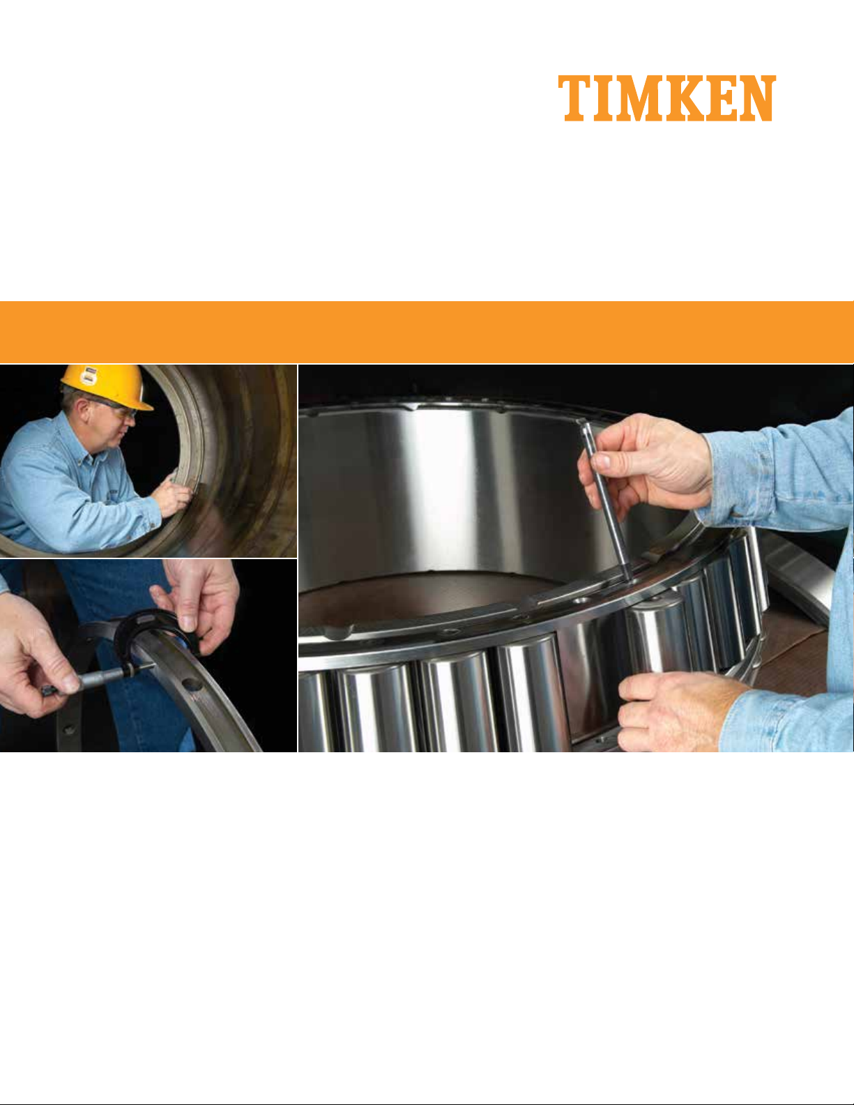
• Remove the bearing from the chock;
• Inspect bearing components and the chock;
• Install the bearing into the chock;
• Inspect the roll neck; and
• Mount the chock assembly onto the roll neck.
TQO bearings are a vital component in the metal rolling industry,
where the operating conditions are harsh, loads are heavy and
contamination by dirt, scale and rolling solution is common. It is
essential to follow proper maintenance practices to ensure reliable operations, peak equipment performance and the lowest
possible maintenance costs.
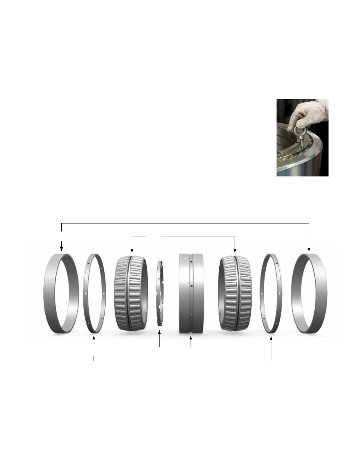
The TQO bearing is the most commonly used anti-friction roll
neck bearing in the metal rolling industry. It includes five components: two double cones (Fig. 1), one double cup (Fig. 2),
two single cups (Fig. 3), two cup spacers (Fig. 4) and one cone
spacer (Fig. 5).
TQO bearings range in size from 83.4
mm (3.281 in.) to 1915.00 mm (75.394 in.)
in outside diameter (O.D.). The basic
construction is the same in all sizes.
However, based on the size of the TQO
bearing, cage types differ. Smaller
sizes feature a stamped steel cage
design. Larger TQO bearings have
either a pin-through-the-roller- or external-pin-type cage with lifting holes
in the cage rings (Fig. 6).
Fig. 6 A TQO bearing with
lifting holes in the cage ring
Fig. 3
TQO Bearing Components
Fig. 4
Fig. 1
Fig. 5 Fig. 2
TIMKEN® TQO BEARING MAINTENANCE MANUAL
3
One of the most important steps in maintaining your TQO bearing is keeping accurate service records. The Timken Roll Neck
Bearing Service Record card (Fig. 7) is available to record the
chock, roll and stand number; cup load zones; and tonnages
or hours used. These cards should be kept up-to-date with
every inspection.
Bearings must be removed from operation and inspected regularly to ensure maximum roll neck bearing life. The frequency of
the inspections will vary with the operating conditions, but are
often conducted at three-, six- or even 12-month intervals. These
inspections allow you to identify trouble areas before they become serious.
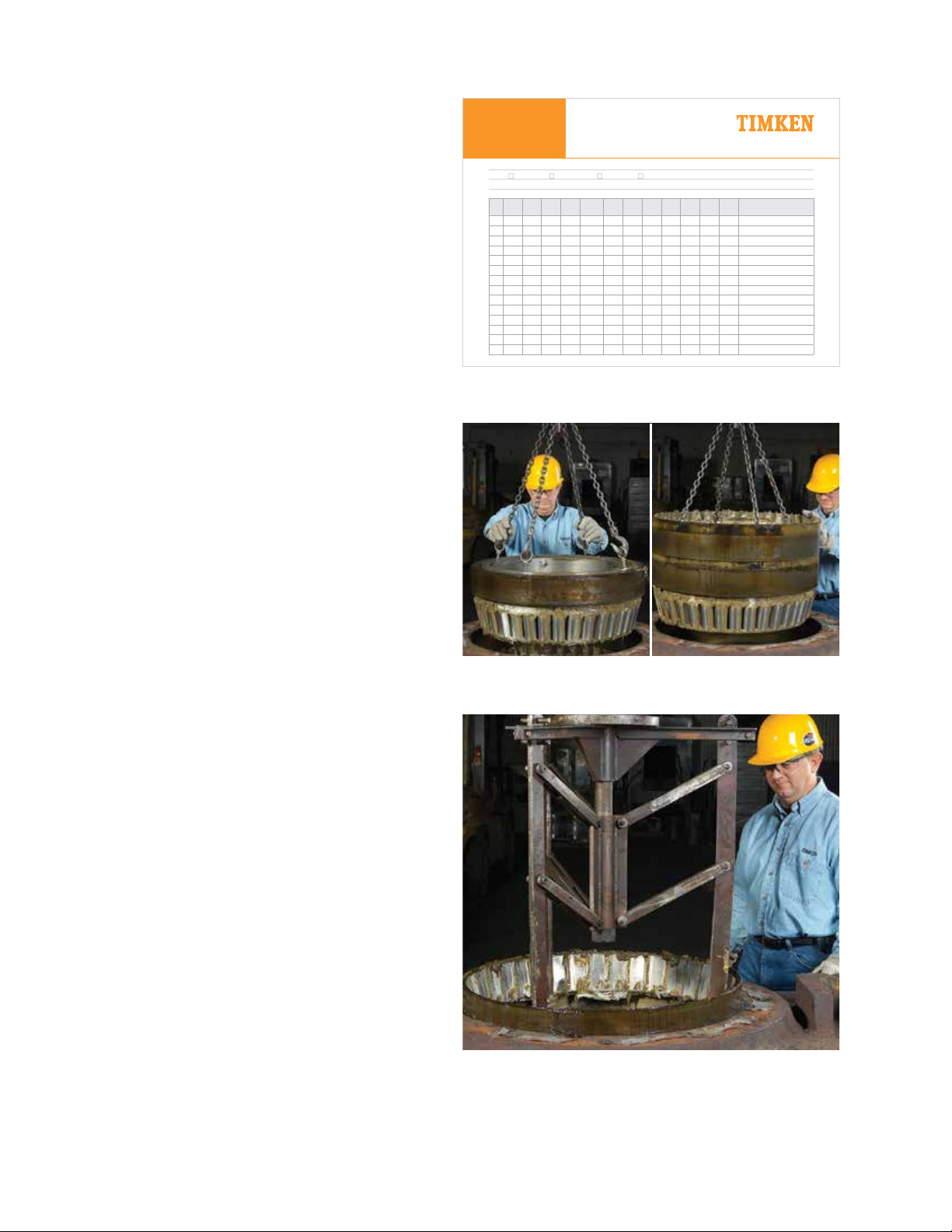
REMOVE THE BEARING FROM THE CHOCK
Special lifting methods and handling tools are used to remove
the bearing from the chock and handle the bearing during inspection. For pin-type cage bearing designs, bearing removal is
usually completed in three lifts. The first lift (Fig. 8) removes the
top single cup and double cone. Four eye bolts and locking nuts
are inserted into the lifting holes of the cage to remove these
components. The locking nut should be tightened against the
cage, prior to lifting.
Roll Neck
Bearing Service
Record
Plant: Mill:
Two-row: Four-row: Back-up Roll: Work Roll: Lubricant:
Serial Number: Part Number/Assembly Number: BEP/RIC:
Times
Chock
In
Service
1
2
3
4
5
6
7
8
9
10
11
12
13
14
Roll
Date In
No.
No.
Cup
Stand
No.
Position
T □ D □
B □ O □
T □ D □
B □ O □
T □ D □
B □ O □
T □ D □
B □ O □
T □ D □
B □ O □
T □ D □
B □ O □
T □ D □
B □ O □
T □ D □
B □ O □
T □ D □
B □ O □
T □ D □
B □ O □
T □ D □
B □ O
T □ D □
B □ O □
T □ D □
B □ O □
T □ D □
B □ O □
A Cup
Service
Service
Total
Load
Date Out
Down
Zone
□
Hours
□
□
□
□
□
□
□
□
□
□
□
□
□
□
Total
Tons
Hours
Tons
Fig. 7 The Timken Roll Neck Bearing Service Record card
Remarks On Nature Of
Repairs And Inspections
The second lift (Fig. 9) removes the double cup, bottom double
cone, along with the cone spacer and top cup spacer. Again,
the lifting holes in the bottom double cone are used to remove
these components.
The final lift (Fig. 10) removes the bottom single cup and cup
spacer. The bearing hook is used to remove these components.
Smaller TQO bearings with stamped steel cages also require
three lifts and special lifting fixtures. Contact your Timken representative for more information.
Fig. 8 Remove the top single cup
and double cone
Fig. 9 Remove the double cup, bottom
double cone, cone spacer and top
cup spacer
Fig. 10 Remove the bottom single cup and cup spacer
TIMKEN® TQO BEARING MAINTENANCE MANUAL
4
INSPECT BEARING COMPONENTS
CLEAN THE BEARING
After removal, clean the TQO bearing to eliminate any accumulation of scale, water, lubricant, debris or other contaminants
which can cause damage to the bearing. The bearing must be
cleaned thoroughly to allow for proper inspection. Small bearings or small quantities of bearings may be cleaned in a commercially available parts cleaner that circulates a cleaning solution such as kerosene, mineral spirits, or other OSHA approved
commercial solvents. Large bearings may be cleaned in a wash
tank that circulates alkali cleaners.
Alkali cleaners such as tri-sodium phosphate (TSP), soda ash, or
metasilicate should be mixed with the ratio of 15 to 25 ml per liter
(2 to 3 ounces per gallon) of hot water. These hot water solutions
often are used as a final cleaning or rinse after the initial bearing
cleaning in a hot oil tank. The cleaning tank should have provisions for heating the oil or water solution as well as for agitating
or recirculating the cleaner.
After cleaning, the bearing should be covered with a
coating of light oil to protect against rusting if it is not
inspected immediately.
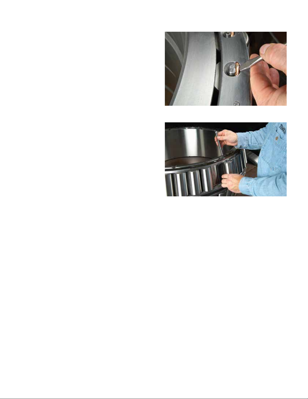
Fig. 11 Remove the pin locking wire
INSPECT FOR DAMAGE
After cleaning the bearing, it is necessary to visually inspect the
bearing components for damage and wear. Rollers can be inspected by rotating the cage or by turning the individual rollers.
The pin-type cages on most large bearing cones have one or
two inspection pins which allow you to remove individual rollers.
These pins can be removed by prying out the locking wire and
unscrewing the pin (Fig. 11). Drawings of pin removal sockets
can be provided by your Timken representative.
Next, remove the roller to inspect the cone O.D. or raceway (Fig.
12). If small spalls or surface breakouts are found on the cone
O.D. or rollers, minor repairs often can be made to the bearing.
Any component damage should be recorded.
The cone and rollers are the rotating bearing parts in a roll neck
application. All areas of the cone O.D. will carry part of the rolling load during each revolution of the cone assembly. Large
spalled areas on the cone O.D. will not be able to support the
rollers under the load. Repairing large spalls in this location is
not suggested.
Fig. 12 Remove the roller to inspect the bearing raceway for damage
To complete the cone inspection, reinstall the rollers, retighten the inspection pins and replace the locking wires. The
cone bore should also be measured to check that it is within
the manufacturer’s acceptable limits.
Bearing cups should be wiped clean and thoroughly inspected.
The condition of these components can provide information
about problems in the mill. Contact your Timken representative
to discuss the cause of the damage and to help determine a
corrective action plan.
Rollers cannot be removed from stamped-steel-type cage assemblies. If damage is found on the assembly, the bearing may
be repaired at a Timken service facility.
TIMKEN® TQO BEARING MAINTENANCE MANUAL
5
 Loading...