

Page 1
METALS INDUSTRY EDITION
TIMKEN ENGINEERING MANUAL
Page 2

TIMKEN ENGINEERING MANUAL
Page 3

TIMKEN ENGINEERING MANUAL -
METALS INDUSTRY EDITION
INDEX
TIMKEN OVERVIEW.................................................................................2
Shelf Life Policy ................................................................................... 8
Storage .................................................................................................9
LUBRICATION AND SEALING ..............................................................95
Lubrication ..............................................................................................96
Lubrication Fundamentals ............................................................... 96
Main Lubricant Characteristics ...................................................... 99
Lubrication Selection .....................................................................100
Sealing ................................................................................................... 110
Sealing Types ...................................................................................110
Sealing Systems .............................................................................. 112
POPULAR BEARING TYPES IN THE METAL INDUSTRY .................. 11
Steelmaking ............................................................................................12
Continuous Casting ................................................................................ 13
Rolling Mill Stands ................................................................................. 14
Radial Bearings ................................................................................. 14
Thrust Bearings ................................................................................. 16
Auxiliary Equipment ............................................................................... 18
APPLICATION CONSIDERATIONS AND BEARING SELECTION ..... 21
Steelmaking ............................................................................................22
Continuous Casting ................................................................................ 27
Rolling Mill...............................................................................................33
Flat Product Rolling...........................................................................33
Long Product Rolling ........................................................................35
Bearing Solutions: Radial Positions .................................................... 36
Work and Intermediate Rolls: Flat Product Mills .........................36
Work Rolls: Long Product Mills ......................................................43
Backup Rolls ...................................................................................... 46
Bearing Solutions: Axial Positions ...................................................... 53
Auxiliary Equipment ............................................................................... 58
Main Mill Drive and Pinion Stand Gearboxes .............................. 58
Pay-off and Rewind Reels ............................................................... 60
Shears and Shear Drives ................................................................. 62
Table Rolls .......................................................................................... 64
BEARING LIFE CALCULATIONS AND RELATED ANALYSIS ............ 67
Summary of Symbols ............................................................................. 68
Fatigue Life .............................................................................................. 69
Bearing Ratings ...................................................................................... 69
Applied Loads ......................................................................................... 72
Bearing Life Equations .......................................................................... 81
Bearing Internal Clearance .................................................................. 86
Advanced Analysis ................................................................................ 92
APPLICATION CHALLENGES AND ENHANCED
BEARING SOLUTIONS.........................................................................115
High-Performance Bearings .............................................................. 116
Contact Fatigue ....................................................................................117
Debris ..................................................................................................... 120
Lubrication ............................................................................................122
Corrosion ............................................................................................... 124
Precision Rolling ..................................................................................126
High Acceleration ................................................................................ 127
RELATED PRODUCTS...........................................................................129
Seals and Lubricant ............................................................................. 130
Maintenance Tools .............................................................................. 131
Condition Monitoring Equipment ....................................................... 133
®
Timken
Timken Quick-Flex
Precision Chain Products ................................................................... 140
BEARING STORAGE, HANDLING AND INSTALLATION ................143
Bearing Packaging and Storage ....................................................... 144
Bearing Marking ..................................................................................144
Roll Neck Maintenance Guidelines .................................................. 147
Chock and Roll Neck Maintenance Guidelines .............................. 151
Mounting and Dismounting Roll Neck Bearings ............................157
Bearing Setting Techniques ............................................................... 168
SERVICES ..............................................................................................175
Gearbox Repair.....................................................................................176
Bearing Reconditioning and Reclamation ....................................... 177
Chock and Roll Upgrades ................................................................... 180
MILLTEC™ Rolling Mill Program ........................................................182
Service Engineering ............................................................................182
Training .................................................................................................. 182
Housed Units ........................................................................ 134
®
Couplings .......................................................... 138
TIMKEN ENGINEERING MANUAL
1
Page 4

TIMKEN
GROW STRONGER WITH TIMKEN
GROW STRONGER WITH TIMKEN
Every day, people around the world count on the strength
of Timken. Our expertise in metallurgy, friction management
and mechanical power transmission helps them accelerate
improvements in productivity and uptime.
We supply products and services that can help keep your
operations moving forward, whether you need drive train kits
for commercial vehicles, durable housings for bearings in dirty
environments, couplings that avoid metal-to-metal contact
between motors and gearboxes, repair services for bearings
and gearboxes, roller chain for dry, abrasive and high-moisture
applications, steel for an aircraft engine shaft, or other
products or services for your applications.
When you choose Timken, you receive more than high-quality
products and services: you gain a worldwide team of highly
trained and experienced Timken people committed to working
collaboratively with you to improve your business.
Globally, our 20,000 people provide reliable answers for a
wide range of operations in manufacturing, mining, medical
equipment, aerospace, transportation, oil and gas – and other
diverse industries.
TIMKEN ENGINEERING MANUAL
2
Page 5

INCREASE YOUR EQUIPMENT
UPTIME
In addition to high-quality bearings and mechanical power
transmission components, we provide valuable integrated
products and services. For example, we offer repair services
and equipment monitoring equipment that can alert you to
problems before they impact your uptime.
Additionally, we offer a broad selection of seals, premium
lubricants, lubricators, couplings and chain to keep your
TIMKEN
INCREASE YOUR EQUIPMENT UPTIME
operations moving smoothly.
Our technology centers in the United States, Europe and
Asia help pioneer tomorrow’s innovations with extensive
basic and applied scientific research programs. Through
internal development and strategic acquisition of innovative
companies, we continue to expand our portfolio of highly
engineered bearings and components.
TIMKEN ENGINEERING MANUAL
3
Page 6

TIMKEN
METALS INNOVATOR
METALS INNOVATOR
Today, metal processing equipment handles heavier loads,
faster speeds and greater output than ever before. Finished
product quality requirements increase, while across the
industry manufacturers continue to place a very high premium
on equipment uptime and performance.
As the leader in friction-management and power-transmission
solutions for the metals industry, Timken helps metals operators
improve their equipment’s performance and uptime. We
accomplish this by providing custom solutions – from bearings
that can stand up to harsh environments to condition monitoring
that helps minimize maintenance costs and improve
plant productivity.
We have more than a century of experience developing
bearings and related solutions that help equipment run
more efficiently in a wide range of applications, including
steelmaking, continuous casting and rolling both flat and long
products.
INNOVATION AND
CUSTOMER SUPPORT
Timken operates technology centers around the world
dedicated to developing innovative concepts and products that
help you operate more efficiently. Our technical leadership and
customer support reaches far beyond our products. Timken
customers have access to sales and service engineering
support at their plants and options for additional support from
application engineers, who specialize in the metals industry.
CORE CAPABILITIES
Timken has evolved from its early roots as a bearing and
steel producer to a supplier offering much more, including
friction-management and power-transmission solutions that
add value throughout the complete life cycle of a system. Our
material enhancements improve bearing life and can protect
against debris and corrosion – two common challenges in
processing metals. Our precision manufacturing capabilities
and commitment to quality ensure global consistency in
design and manufacturing at every Timken facility. A global
distribution network provides our customers with easy access
to Timken products and services throughout the world.
We leverage these core capabilities as we work with
original equipment manufacturers (OEM) and designers
to integrate our technologies into equipment so that end
users can enjoy the performance benefits of Timken
products from the first day of operation. OEMs depend
on Timken for our engineering expertise, manufacturing
capabilities and emphasis on reliable performance.
TIMKEN ENGINEERING MANUAL
4
Page 7

PRODUCTS AND SERVICES
We offer equipment builders and operators one of the most
extensive friction-management product and service portfolios
in the industry.
BEARINGS
We provide a broad range of bearing designs and
configurations for use in steelmaking vessels, caster segments,
work rolls, backup rolls, screwdown systems, mill drives,
pinion stands, coilers, table rolls, and auxiliary equipment.
Bearing types include:
Tapered roller bearings – Tapered roller bearings are
•
uniquely designed to manage both thrust and radial loads
and are available in single- and multi-row designs with a
wide range of assembly options. Our extensive offering
of tapered roller bearing combinations offers equipment
builders and operators simple, reliable and less costly
design solutions.
Cylindrical roller bearings –This design generally offers
•
the highest possible radial load capacity for a given size
compared to other roller bearing types. One row and two
row cylindrical roller bearings are ideal for many mill stand,
gear drive and other auxiliary equipment applications,
while four row cylindrical roller bearings are used in roll
neck applications. Timken offers both single and multi-row
cylindrical roller bearing. Custom designs are available
upon request for specific applications.
TIMKEN
PRODUCTS AND SERVICES
Thrust roller bearings – Thrust roller bearings for rolling
•
mill applications are available in cylindrical, spherical and
tapered designs. Thrust bearings are ideal for applications
experiencing heavy axial loads, such as mill stands,
screwdown systems and piercing mills.
Ball bearings – Ball bearings are used extensively in
•
auxiliary applications that have light loads and/or high
speed conditions. Timken offers a range of radial, thrust
and angular-contact ball bearings in both metric and inch
sizes. Please contact your Timken engineer for detailed
information on these product ranges.
Housed units – Timken® spherical roller bearing solid-
•
block housed units possess a unique cast-steel design
that handles demanding conditions in metal industry
applications. These solid-block housed units come in
several styles and five advanced locking configurations.
Timken spherical roller bearing solid-block housed units
are designed for challenging circumstances. A full line of
primary seals, covers and housings is available to find the
right roller housed unit to fit your application. In case of
high thrust loads, in excess of the spherical roller bearing
carrying capabilities, the Timken
Timken also provides a broad range of split-block housings
in both metric and inch sizes.
®
Type E is your solution.
Spherical roller bearings – Spherical roller bearings offer
•
high radial and moderate thrust capacity together with
maximum static and dynamic misalignment capability.
Timken spherical roller bearings provide high-static load
capacity and advanced geometry that reduces friction and
heat generation. These bearings are available in a range
of dimensionally stabilized configurations to suit elevated
operating temperatures.
TIMKEN ENGINEERING MANUAL
5
Page 8

TIMKEN
PRODUCTS AND SERVICES
HIGH-PERFORMANCE BEARING
SOLUTIONS
Timken provides the metals industry with a variety of
high-performance bearing solutions, including Timken
AquaSpexx
corrosion protection. Our debris-resistant bearings are ideal
for contaminated and/or marginal lubrication conditions.
We also provide customized bearing solutions such as special
race profiles to meet special application requirements.
In addition to component geometry and metallurgy, we find
many ways to enhance bearing performance by applying
unique surface finishes and special coatings on rollers,
raceways and other functional surfaces. Engineered surfaces
and topographical modification reduce surface roughness
to lower levels than can be achieved through conventional
grinding and honing methods. We also offer proprietary
coatings that can create a surface up to four times harder than
steel with twice the elasticity. For more information on Timken
high-performance bearings and engineered surfaces, see
the Application Challenges and Enhanced Bearing Solutions
section of this manual (pages 115-127).
®
, DuraSpexx® and thin dense chrome bearings for
®
Timken manufactures precision roller
chain that are designed to meet
demanding steel industry applications.
We build chains to precise specifications
for strength and maximum wear life. The
offering includes a complete line of roller
chain, attachment chain and engineered
conveyor chain.
POWER TRANSMISSION
COMPONENTS AND SYSTEMS
Timken offers an expanding range of power transmission
components including seals, couplings and engineered chain.
Extreme temperatures and high contamination levels can
disable your equipment and significantly lower productivity.
Timken develops seals using advanced material and process
solutions that help protect machinery and minimize plant
downtime. We offer a comprehensive line of large-bore oil and
grease seals and metallic and non-metallic bearing isolators.
®
Timken
minimal maintenance. They are easy to install and require no
lubrication. These couplings are designed to connect motors
and gearboxes with other moving equipment with capacity to
transmit the same or more torque than a gear coupling with
the same dimensions. The Quick-Flex coupling's innovative
design utilizes an advanced elastomeric element to transmit
the torque and therefore eliminates any interference between
coupling hubs that can damage equipment.
Quick-Flex® couplings are highly durable, yet need
LUBRICATION
Timken lubricants reduce friction, reduce wear and protect
bearing surfaces from corrosion. We offer a wide selection of
lubricants, including Timken Mill Grease, which we formulated
to perform in the difficult roll neck bearing environment. Timken
single- and multi-point lubricators and lubrication delivery
devices help mill maintenance professionals simplify their
lubrication practices, saving time and money.
TIMKEN ENGINEERING MANUAL
6
Page 9

CONDITION MONITORING DEVICES
Powerful diagnostic tools from Timken are designed to detect
potential bearing failure before it occurs. A variety of handheld
devices and online options – including our ultra-accurate
Online Intelligence System – let you monitor bearing condition,
lubrication quality and machine vibration (either periodically
or continuously) for increased productivity, safety and peace
of mind.
MAINTENANCE TOOLS
Timken maintenance tools may extend bearing life by
facilitating proper installation, removal and service.
They also help simplify maintenance practices.
We provide induction heaters, impact fitting tools
and hydraulic and mechanical pullers.
TIMKEN
PRODUCTS AND SERVICES
SERVICES
Used bearings and related components often can be returned
to their original specifications with less time and costs than
purchasing new. We offer complete remanufacture and
reconditioning services for many components, including
bearings, chocks, housings, rolls and more.
Our gearbox repair services are globally recognized as experts
in power transmission solutions for heavy industrial markets,
repairing virtually any large gearbox make or model, with
onsite emergency breakdown service available if needed.
Timken offers a full range of maintenance and reconditioning
services through our remanufacturing and repair operations.
Using these services can lead to improved plant efficiency and
reduced overall production costs.
Beyond bearing repair and depending on the location, we offer
chock maintenance and roll rebuilding to help mill operators
get the most out of their chock/bearing assembly.
In addition, our MILLTEC
around-the-clock management of the roll shop with the goal of
minimizing operational costs and downtime.
®
rolling mill program provides
TRAINING
We offer industry-specific training programs designed for plant
professionals, as well as on-site customized training to meet
your specific needs. Our metals industry training programs
are available at select locations around the world and cover
every phase of bearing performance in the metal-making
environment. Class time is balanced with extensive hands-on
training and tours of Timken facilities.
TIMKEN ENGINEERING MANUAL
7
Page 10

TIMKEN
HOW TO USE THIS CATALOG • SHELF LIFE AND STORAGE OF GREASE-LUBRICATED BEARINGS AND COMPONENTS
HOW TO USE THIS CATALOG
We designed this catalog to help you find the bearings best
suited to your specifications.
Timken offers an extensive range of bearings and accessories
in both imperial and metric sizes. For your convenience, size
ranges are indicated in millimeters and inches. Contact your
Timken sales engineer to learn more about our complete line
for the special needs of your application.
This publication contains dimensions, tolerances and load
ratings, as well as engineering sections describing fitting
practices for shafts and housings, internal clearances,
materials and other bearing features. It provides valuable
assistance in the initial consideration of the type and
characteristics of the bearings that may best suit your
particular needs.
ISO and ANSI/ABMA, as used in this publication, refer to
the International Organization for Standardization and the
American National Standards Institute/American Bearing
Manufacturers Association.
Updates are made periodically to this catalog. Visit www.
timken.com for the most recent version of the Timken Metals
Engineering Catalog.
DISCLAIMER
This catalog is provided solely to give you analysis tools
and data to assist you in your product selection. Product
performance is affected by many factors beyond the control
of Timken. Therefore, you must validate the suitability and
feasibility of all product selections.
SHELF LIFE AND STORAGE OF
GREASE-LUBRICATED BEARINGS
AND COMPONENTS
To help you get the most value from our products, Timken
provides guidelines for the shelf life of grease-lubricated
ball and roller bearings, components and assemblies. Shelf
life information is based on Timken and industry test data
and experience.
SHELF LIFE POLICY
Shelf life should be distinguished from lubricated bearing/
component design life as follows:
Shelf life of the grease-lubricated bearing/component
represents the period of time prior to use or installation.
The shelf life is a portion of the anticipated aggregate design
life. It is impossible to accurately predict design life due to
variations in lubricant bleed rates, oil migration, operating
conditions, installation conditions, temperature, humidity and
extended storage.
Shelf life values, available from Timken, represent a maximum
limit and assume adherence to the storage and handling
guidelines suggested in this catalog or by a Timken associate.
Deviations from the Timken storage and handling guidelines
may reduce shelf life. Any specification or operating practice
that defines a shorter shelf life should be used.
Timken cannot anticipate the performance of the grease
lubricant after the bearing or component is installed or placed
in service.
Timken products are sold subject to Timken terms and
conditions of sale, which include our limited warranty and
remedy. You can find these at http://www.timken.com/en-us/
purchase/Pages/TermsandConditionsofSale.aspx
Please consult with your Timken engineer for more information
and assistance.
Every reasonable effort has been made to ensure the accuracy
of the information in this writing, but no liability is accepted for
errors, omissions or for any other reason.
TIMKEN ENGINEERING MANUAL
8
TIMKEN IS NOT RESPONSIBLE FOR THE
SHELF LIFE OF ANY BEARING/COMPONENT
LUBRICATED BY ANOTHER PARTY.
European REACH Compliance
Timken lubricants, greases and similar products sold in
standalone containers or delivery systems are subject to the
European REACH (Registration, Evaluation, Authorization
and Restriction of CHemicals) directive. For import into the
Page 11
SHELF LIFE AND STORAGE OF GREASE-LUBRICATED BEARINGS AND COMPONENTS
European Union, Timken can sell and provide only those
lubricants and greases that are registered with ECHA
(European CHemical Agency). For further information, please
contact your Timken engineer.
STORAGE
Timken suggests the following storage guidelines for our
finished products (bearings, components and assemblies,
referred to as “products”):
Unless directed otherwise by Timken, products should be
•
kept in their original packaging until they are ready to be
placed into service.
Do not remove or alter any labels or stencil markings on the
•
packaging.
TIMKEN
Products should be stored in such a way that the packaging
•
is not pierced, crushed or otherwise damaged.
After a product is removed from its packaging, it should be
•
placed into service as soon as possible.
When removing a product that is not individually packaged
•
from a bulk pack container, the container should be
resealed immediately after the product is removed.
Do not use product that has exceeded its shelf life as
•
defined in the Timken shelf life guidelines statement.
The storage area temperature should be maintained
•
between 0º C (32º F) and 40º C (104º F); temperature
fluctuations should be minimized.
The relative humidity should be maintained below 60
•
percent and the surfaces should be dry.
The storage area should be kept free from airborne
•
contaminants such as, but not limited to, dust, dirt, harmful
vapors, etc.
The storage area should be isolated from undue vibration.
•
Extreme conditions of any kind should be avoided.
•
Due to the fact that Timken is not familiar with your particular
storage conditions, we strongly suggest following these
guidelines. However, you may be required by circumstances
or applicable government requirements to adhere to stricter
storage requirements.
Most bearing components typically ship protected with a
corrosion-preventive compound that is not a lubricant. These
components may be used in oil-lubricated applications without
removal of the corrosion-preventive compound. When using
some specialized grease lubrications, we advise you to remove
the corrosion-preventive compound before packing the
bearings components with suitable grease.
We pre-pack most housed unit types in this catalog with
general-purpose grease suitable for their normal applications.
It may be necessary for you to frequently replenish the grease
for optimum performance.
Be careful in selecting lubrication, however, since different
lubricants are often incompatible. You may order housed units
pre-lubricated with a specified lubrication.
When you receive a bearing or housed unit shipment, do not
remove products from their packaging until they are ready for
mounting so they do not become corroded or contaminated.
Store bearings and housed units in an appropriate atmosphere
so they remain protected for the intended period.
TIMKEN ENGINEERING MANUAL
9
Page 12

TIMKEN
SHELF LIFE AND STORAGE OF GREASE-LUBRICATED BEARINGS AND COMPONENTS
WARNING Failure to observe the following warnings could create a risk of serious injury.
Proper maintenance and handling practices are critical.
Always follow installation instructions and maintain proper lubrication.
Warnings for this product line are in this catalog and posted on
www.timken.com/en-us/products/warnings/Pages/default.aspx.
CAUTION Failure to follow these cautions may result in property damage.
If hammer and bar are used for installation or removal of a part, use a mild steel bar (e.g., 1010 or 1020 grade). Mild steel bars are
Timken products are sold subject to Timken’s terms and conditions of sale, which include its limited warranty and remedy,
European REACH compliance Timken-branded lubricants, greases and similar products sold in stand-alone containers or
delivery systems are subject to the European REACH (Registration, Evaluation, Authorization and Restriction of CHemicals)
directive. For import into the European Union, Timken can sell and provide only those lubricants and greases that are registered
less likely to cause release of high-speed fragments from the hammer, bar or the part being removed.
Do not use damaged housed units. The use of a damaged housed unit can result in equipment damage and/or injury.
NOTE
Components may become damaged and affect the performance and service life of the bearing.
Do not mix components of matched assemblies. Mixing components can reduce the service life of the bearing.
This catalog is provided solely to give you analysis tools and data to assist you in your product selection.
Product performance is affected by many factors beyond the Control of Timken.
Therefore, the suitability and feasibility of all product selection must be validated by you.
which terms may be found at http://www.timken.com/en-us/purchase/Pages/TermsandConditionsofSale.aspx.
Please consult with your Timken engineer for more information and assistance.
Every reasonable effort has been made to ensure the accuracy of the information in this writing,
but no liability is accepted for errors, omissions or for any other reason.
To view the complete engineering catalog, please visit www.timken.com. To order the catalog, please contact your
Timken engineer and request a copy of the Timken Engineering Manual, order number 10424.
with ECHA (European CHemical Agency). For further information, please contact your Timken engineer.
Visit www.timken.com for the most recent version of the Timken
Do not attempt to disassemble unitized bearings.
DISCLAIMER
Updates are made periodically to this catalog.
®
Engineering Manual - Metals Industry Edition.
TIMKEN ENGINEERING MANUAL
10
Page 13
POPULAR BEARING TYPES IN THE METALS INDUSTRY
POPULAR BEARING TYPES
IN THE METALS INDUSTRY
The following applications are covered in this
section:
Steelmaking.
•
Continuous casting.
•
Rolling mill stands.
•
Radial bearings.
•
Thrust bearings.
•
Auxiliary equipment.
•
TIMKEN ENGINEERING MANUAL
11
Page 14
POPULAR BEARING TYPES IN THE METALS INDUSTRY
STEELMAKING
STEELMAKING
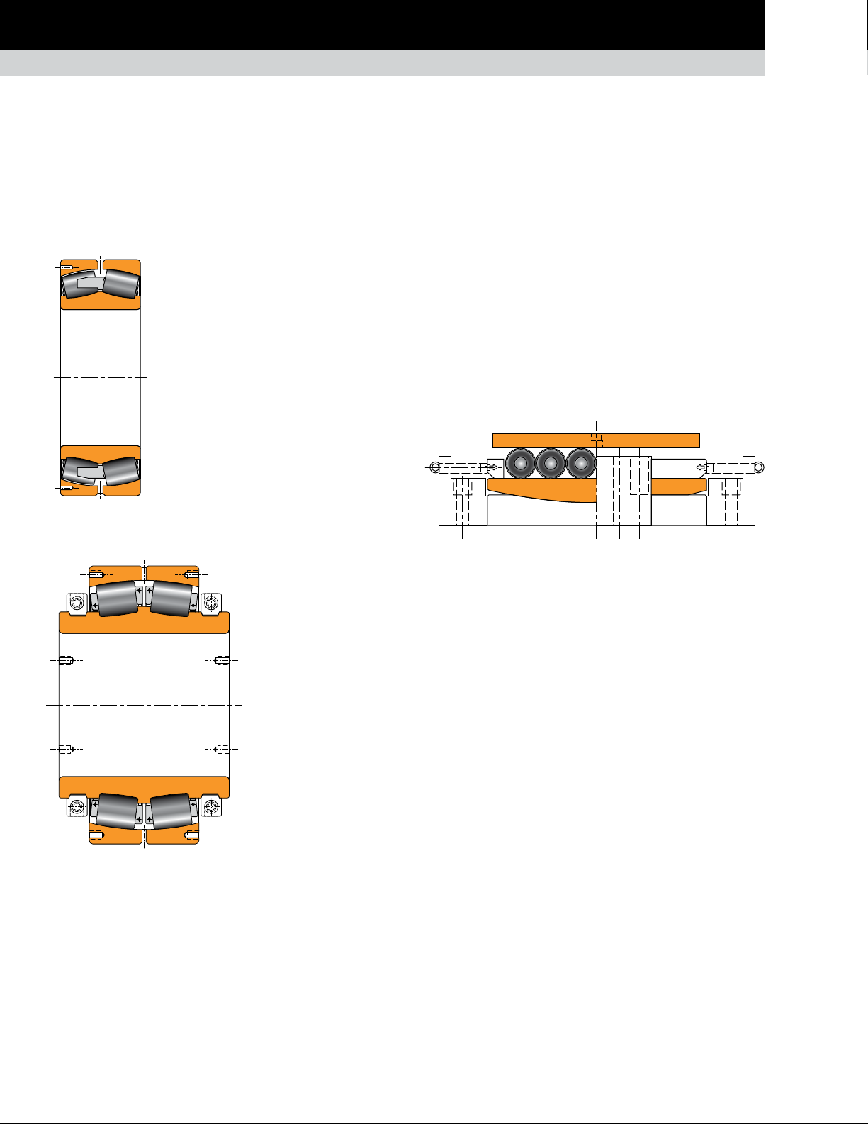
The main support positions for the ladle furnace present a challenging application for bearings. They experience very high loads
and misalignment at very low speeds. In addition, cyclic and reversing rotation occurs. The Timken solution uses solid or split
high-performance spherical roller bearings mounted in custom-designed housings. The float position housing incorporates cylindrical
roller ladder bearings to accommodate the significant thermal axial growth of the furnace assembly.
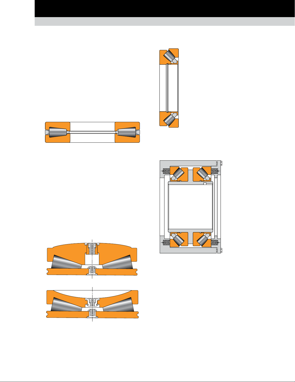
SPHERICAL ROLLER BEARINGS
YMB TYPE
Composition: One double inner ring, one
double outer ring, two rows of spherical rollers
with land riding one-piece brass cage.
Application: Basic oxygen furnace (BOF) or
argon oxygen decarburization (AOD) furnace
pivots (trunnions).
Remarks: YMB type is designed for large size
bearings to manage high radial loads when
shaft deflection is important.
Fig. 1. YMB type.
SPLIT TYPE
Composition: One split
double inner ring with
clamp rings, one split
double outer ring, two rows
of spherical rollers with
steel pin-type split cages.
LADDER BEARINGS
CYLINDRICAL ROLLER TYPE
Composition: One top plate, one bottom plate, cylindrical rollers
with spring-centered retainer and one bottom seat.
Application: Linear bearing for float side BOF or AOD furnace
pivot bearing assembly.
Remarks: Used in pairs. Provide ± 65 mm (2.5 in.) axial float.
Fig. 3. Cylindrical roller type.
Fig. 2. Split type.
12
TIMKEN ENGINEERING MANUAL
Application: BOF or AOD
furnace pivots (trunnions).
Remarks: Often used to
replace conventional
spherical roller bearings on
drive-side pivot (trunnion).
Page 15
POPULAR BEARING TYPES IN THE METALS INDUSTRY
CONTINUOUS CASTING
CONTINUOUS CASTING
The continuous caster presents one of the most challenging environments for bearings. Caster-roll support bearings are subjected to
high loads and low rotational speeds, often at elevated temperatures. Below the bender segments, the Timken ideal solution combines
our high-performance spherical roller bearing for the fixed position and our latest design innovation, the Timken
for the floating position.
®
ADAPT™ bearing,
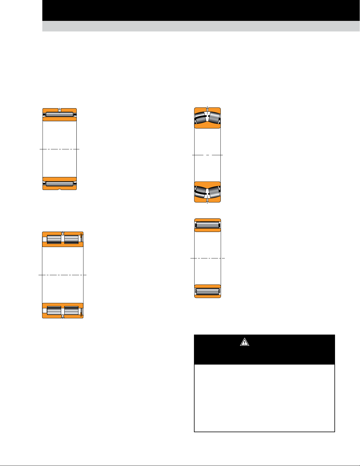
NEEDLE ROLLER BEARINGS
NA TYPE
Composition: One single inner ring, one
single outer ring, one or two rows of caged
needle rollers.
Application: Bender section support rolls.
Remarks: Low radial cross section with
high radial dynamic and static load rating.
Available with special clearance and higher
stabilizing heat treatment to accommodate
Fig. 4. NA type.
continuous caster operating conditions.
CYLINDRICAL ROLLER BEARINGS
NNCF TYPE
Composition: One double inner ring,
one double outer ring, two rows of
full-complement cylindrical rollers.
SPHERICAL ROLLER BEARINGS
EJ TYPE
Composition: One double inner ring, one double
outer ring and two rows of spherical rollers with
stamped steel cages.
Application: Caster rolls; fixed and float positions.
Remarks: EJ-type spherical roller bearings feature
a hardened stamped steel window-type cage with
face slots for improved lubrication. Designed to
accept misalignment during operation and with
high radial load capacity for maximum reliability.
Fig. 6. EJ type.
ADAPT
Composition: One single cylindrical inner ring,
one single profiled outer ring, full-complement
design with a roller/retainer assembly.
Application: Caster rolls; float position.
™
Application: Continuous caster bender
section support rolls.
Remarks: Available with special clearance
and higher stabilizing heat treatment
to accommodate continuous caster
operating conditions. This type includes
Fig. 5. NNCF type.
direction and permit small axial displacement.
integral flanges on inner and outer rings
and can manage light axial loads in one
Remarks: The ADAPT full-complement roller
bearing is designed specifically for continuous
casters, combining traditional cylindrical and
spherical roller bearing configurations into a new
Fig. 7. ADAPT™.
and high axial displacement capabilities). This bearing also offers
high-static radial load capacity for optional reliability.
design so operators benefit from the key attributes
of both types (simultaneous full misalignment
WARNING
Failure to observe the following warnings could
create a risk of serious injury.
ADAPT™ bearings feature a separable inner ring. Care
must be taken when handling or installing a fully assembled
bearing to prevent the inner ring from accidentally sliding
out of the assembly. When using this bearing to replace a
unitized bearing it is important to check the design of the
installation for positive retention on the shaft.
Proper maintenance and handling practices are critical.
Always follow installation instructions and maintain
proper lubrication.
TIMKEN ENGINEERING MANUAL
13
Page 16
POPULAR BEARING TYPES IN THE METALS INDUSTRY
ROLLING MILL STANDS
ROLLING MILL STANDS
Rolling mill applications typically encounter very high radial loads and varying degrees of axial load while running at slow to highspeed. To accommodate these operating conditions, roll neck bearings must have enhanced contact surfaces, material strength
properties, and internal geometry and cage characteristics. Available designs include two-, four- or six-row tapered roller bearings,
and multi-row cylindrical bearings.
RADIAL BEARINGS
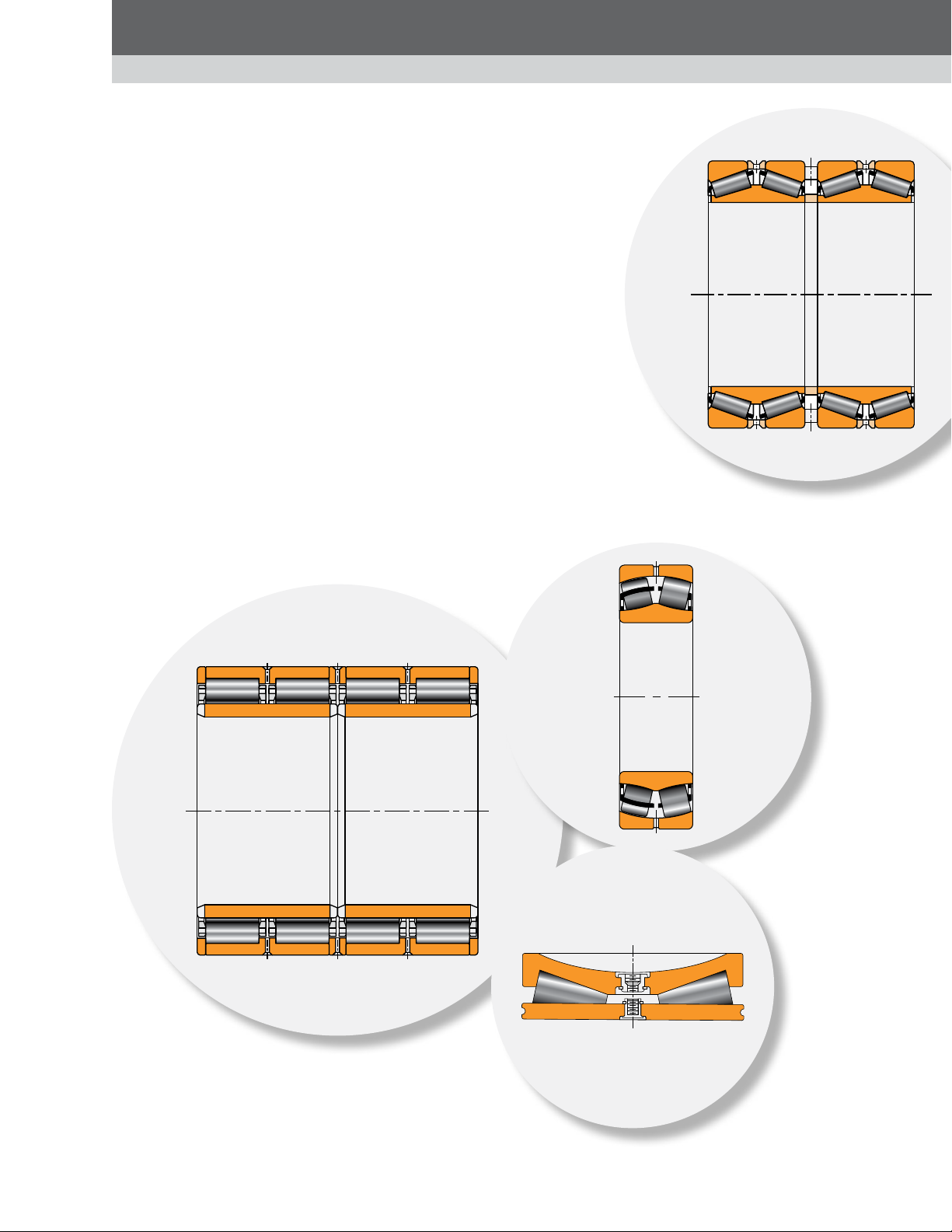
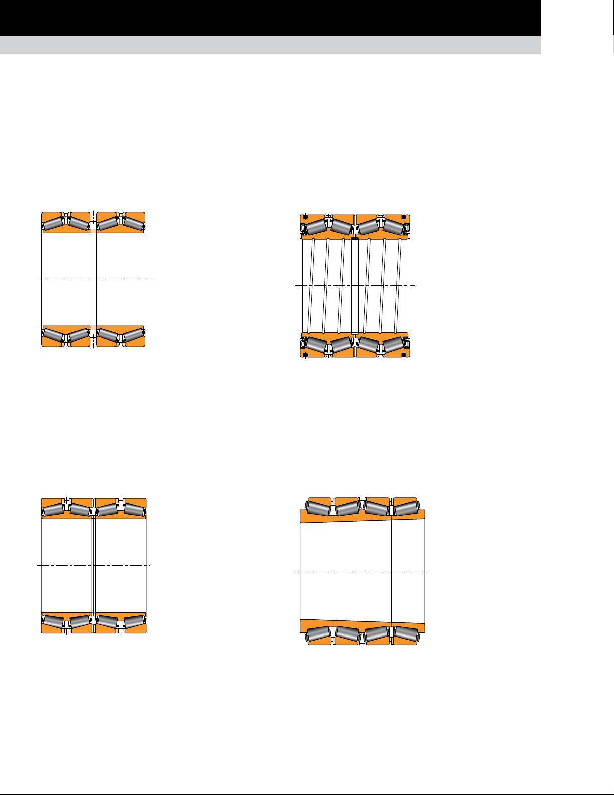
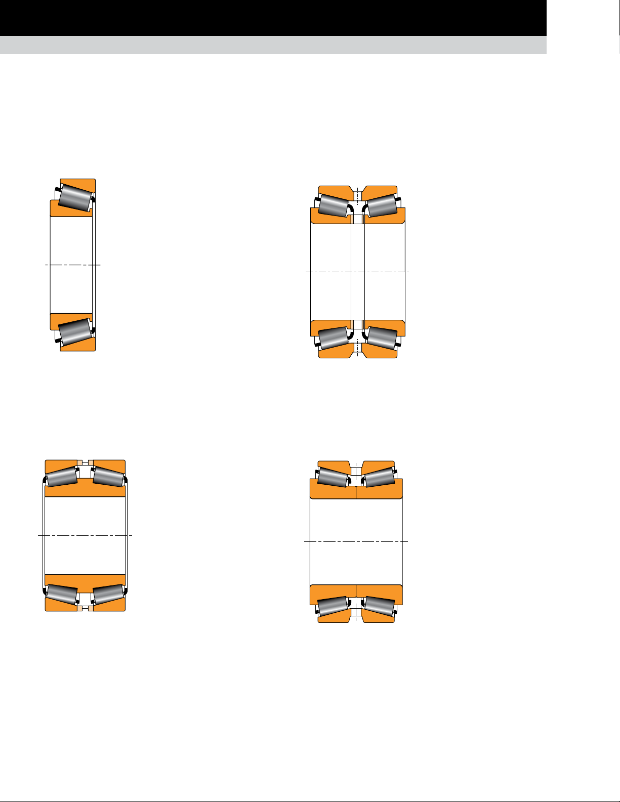
TAPERED ROLLER BEARINGS
TQOW
Composition: Two double cones
with tapered rollers, one cone
spacer, two single cups, two cup
spacers, one double cup.
Application: Work rolls,
intermediate rolls and backup
rolls. Typically used in mills with
speeds up to 800 m/min. (2600 ft./
Fig. 8. TQOW.
Remarks: The TQOW is a preset four-row assembly with
hardened cone spacers to minimize face wear. The bearing
clearance in the TQOW design can be reset after extended use
by regrinding the spacers.
The bearing is mounted loose on the roll neck and in the chock.
Slots on the cone faces provide lubrication access to cone and
fillet ring faces for reduced wear. Available with spiral bore
groove for additional lubrication access to the roll neck.
min.) when used on backup rolls.
2TDIW
Composition: Two double cones
with tapered rollers, four single
cups, and two or three cup
spacers.
Application: Work rolls,
intermediate rolls and backup
rolls. Typically used in mills with
speeds up to 800 m/min. (2600 ft./
Fig. 9. 2TDIW.
Remarks: The 2TDIW type interchanges with the TQOW type on
external boundary dimensions and achieves the same load rating.
Under combined axial and radial loads, the two central single
cups of the 2TDIW bearing offer better load distribution than the
double cups used in the TQOW type.
min.) when used on backup rolls.
Sealed roll neck
bearing
Composition: Same
construction as the 2TDIW, plus
two main seals, one bore seal,
and O-ring to seal statically in
the chock bore.
Application: Primarily used in
work rolls and intermediate rolls
and some backup rolls.
Fig. 10. Sealed roll neck bearing.
Remarks: The sealed roll neck
bearing is supplied as a unitized, preset assembly with or
without grease.
TQITS
Composition: One double
cone and two single cones all
with matched tapered bores,
four single cups, three cup
spacers.
Application: Backup rolls,
typically used in high-speed
mills where strip speeds
exceed 800 m/min. (2600 ft./
min.).
Fig. 11. TQITS.
Remarks: The TQITS type
mounts tight using a 1:12 taper on the roll neck and the bearing
bore for accurate control of the interference fit. Typically used
on high-speed mills to minimize neck wear.
14
TIMKEN ENGINEERING MANUAL
Page 17
POPULAR BEARING TYPES IN THE METALS INDUSTRY
ROLLING MILL STANDS
CYLINDRICAL ROLLER BEARINGS
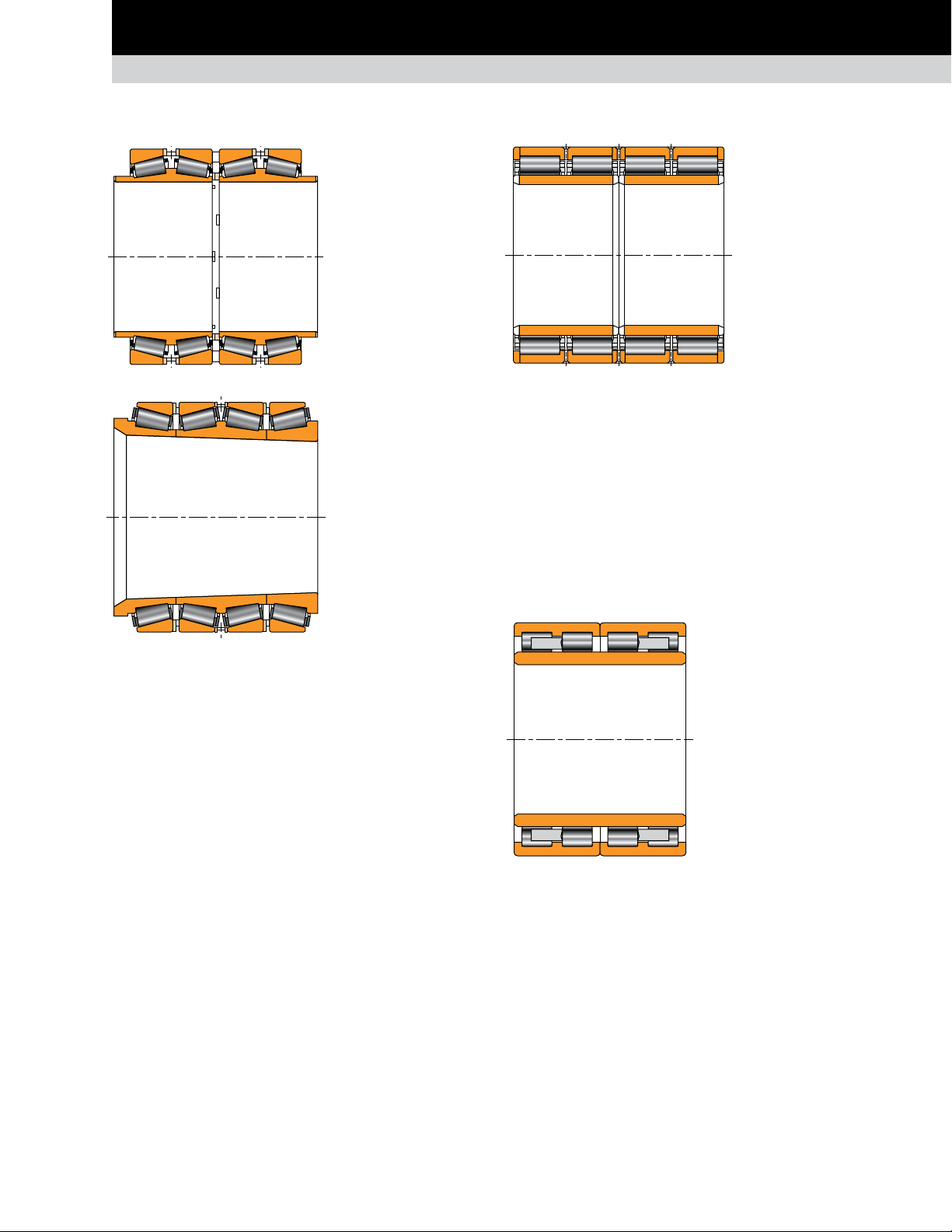
Fig. 12. TQOWE.
Fig. 13. TQITSE.
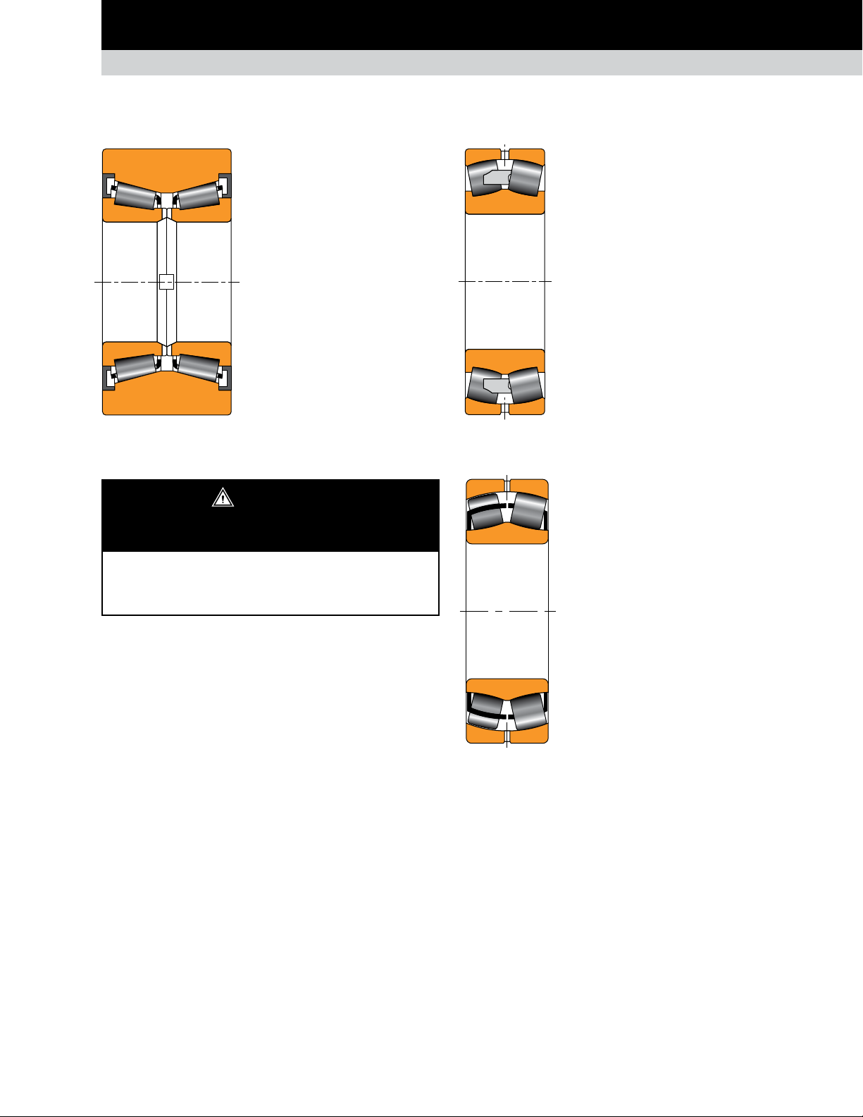
TQOWE and TQITSE
Composition: Same
construction as the TQOW
and TQITS respectively
with cone extension on
one or both sides of the
bearing.
Application: Work rolls,
intermediate rolls and
backup rolls.
Remarks: The TQOWE
and TQITSE versions
include cone extensions
to accommodate chock
seals. This bearing design
allows an optimal chock
seal running surface.
The seal integration
permits the bearing to be
positioned closer to the
roll face, which improves
the neck stiffness.
RX
Composition: Tw o
cylindrical inner rings,
two flanged outer rings
and separated rib rings
for roller spacing.
Typically includes a pintype cage(s).
Application: Backup roll
Fig. 14. RX.
Remarks: The bearing is mounted tight on the roll neck and loose
in the chock when used on backup rolls. Generally provided with
semi-finished (CF) inner ring races to be finished ground by the
customer once mounted on the roll neck. Separated rib rings
allow for complete disassembly for inspection. The RX style
is usually preferred in bearings above 400 mm (15.75 in.) bore.
Long product mill applications are generally supplied as preset
assembly and mounted tight on the roll neck.
radial position for flat
product mills. Roll neck for
long product mills.
RY and RYL
Composition: Typically one
single-piece inner ring, two
outer rings with triple flanges
(solid ribs). Fully machined
brass (RY) or steel (RYL) cages.
Application: Roll neck for long
product mills.
Remarks: The most recent RYL
design is specifically designed
Fig. 15. RY and RYL.
features a machined-steel cage and enhanced design features
to maximize bearing life and optimize bearing handling. For
specific applications, four-row cylindrical roller bearings also
can be supplied with spiral grooves on inner ring bore, extended
inner rings or tapered bore.
for long-product mills and
TIMKEN ENGINEERING MANUAL
15
Page 18
POPULAR BEARING TYPES IN THE METALS INDUSTRY
ROLLING MILL STANDS
THRUST BEARINGS
Applications mounted with cylindrical roller bearings, oil-film bearings or systems with axial shift or roll crossing, generally need an
additional thrust bearing.
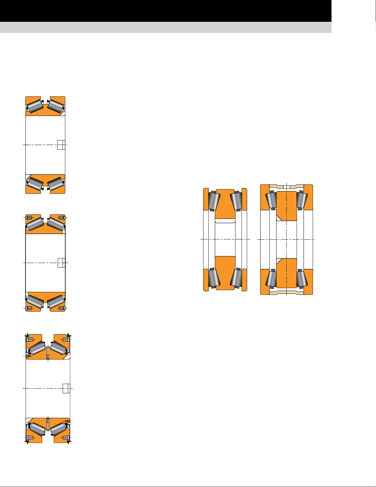
TAPERED ROLLER THRUST BEARINGS
Fig. 16. TDIK.
Fig. 17. TDIK with
spring system.
TDIK
Composition: One double cone with tapered
rollers, two single cups, spacer or spacerless.
Application: Backup and work roll thrust
positions for flat product mills.
Remarks: These bearings come designed
with steep angles to accommodate thrust
in both directions. Cups and cones are
mounted with a loose fit. The cone is keyed
onto the shaft to prevent cone rotation and
bore fretting.
TDIK with spring system
Timken developed a version with
a spring system in the cups without a spacer
to ensure that the unloaded cup always
remains seated and to help prevent any
roller skewing.
Application: Work rolls, intermediate rolls
with axial shift, and backup roll equipped
with cylindrical roller bearing.
TDIK sealed with spring system
Timken developed the sealed version of the
TDIK with a spring system.
TTDWK and TTDFLK
Composition: One double central ring with tapered rollers, two
outer rings.
Application: Heavy-duty flat product mills with axial shift and
long product mills.
Remarks: Double-acting thrust bearings come available in two
versions with tapered central ring or flat central ring. Mounted
loose on the neck and in the housing.
Fig. 19. TTDWK. Fig. 20. TTDFLK.
The tapered central ring version enables a smaller overall width
of the bearing. These TTDFLK assemblies can be provided with
or without an outer spacer. However, we generally prefer to use
the design without outer spacers and include a spring mounting in
the chock shoulders to ensure that the rollers of both rows remain
properly seated (see configuration on page 55).
Application: Work rolls, intermediate rolls
with axial shift, and backup roll equipped
with cylindrical roller bearing.
Fig. 18. TDIK with sealed spring system.
16
TIMKEN ENGINEERING MANUAL
Page 19
POPULAR BEARING TYPES IN THE METALS INDUSTRY
ROLLING MILL STANDS
SPHERICAL ROLLER THRUST BEARING
TTHD
Composition: Two tapered thrust rings, cage or cageless.
Application: Thrust positions for piercing mills, sendzimir mills
and auxiliary equipment.
Remarks: This design offers up to 40 percent more capacity
than cylindrical and spherical bearings with the same envelope
dimensions. Used only when axial loads are unidirectional. Medium
speed capability when provided with a cage. A cageless design is
available for high loads and low speeds.
Fig. 21. TTHD.
TTHDFLSX and TTHDFLSV
Composition: Identical to the TTHD construction with a top ring
generally made with convex outer face (TTHDFLSX). A concave
(TTHDFLSV) top ring also can be supplied if needed.
Application: Screwdown thrust bearing.
Remarks: Full-complement design for maximum capacity. Lifting
holes exist in each ring for handling purposes.
Both designs are also available with a tapered bottom race design
(TTHDSX and TTHDSV).
TSR
Composition: One single inner ring with spherical
rollers with cage retainer and one single outer ring.
Application: Thrust position for gearboxes and
auxiliary equipment.
Remarks: Type TSR spherical roller thrust bearings
maintain a high-thrust capacity and accommodate
misalignment.
Fig. 24. TSR.
2TSR assembly
Composition: Two single
inner rings with spherical
rollers and cage retainer
installed in a sleeve and
two single outer rings, all
mounted in a carrier.
Application: Thrust
position for gearboxes
and auxiliary equipment.
Fig. 22. TTHDFLSX.
Fig. 23. TTHDFLSV.
Remarks: To maintain
loading in the row
unloaded by the axial
Fig. 25. TSR assembly.
TIMKEN ENGINEERING MANUAL
load, the whole assembly
is preloaded using springs
mounted in the carrier.
17
Page 20
POPULAR BEARING TYPES IN THE METALS INDUSTRY
AUXILIARY EQUIPMENT
AUXILIARY EQUIPMENT
Timken offers a wide range of bearings for auxiliary equipment applications such as gear drives, table rolls, coilers, end coilers,
levelers, pinion stands, handling equipment and more.
TAPERED ROLLER BEARINGS
Fig. 26. TS.
TS
Composition: One single cone with tapered
roller and one single cup.
Application: Saws, guiding rolls, scrap choppers
and small drives.
Remarks: The TS is the most common tapered
roller bearing that allows the designer a
large choice of mountings. TS bearings
always are fitted in pairs, whether mounted
directly like a TDI or indirectly like a TDO.
TDI AND TDIT
Composition: One double cone, two
single cups, spacer or spacerless.
TDI version with straight
bore (illustrated).
TDIT version with a tapered bore.
TDO
Composition: Two single cones,
one double cup and one cone
spacer.
Application: Mill drives, pinion
stands, coilers, uncoilers, side
trimers and scrap choppers.
Remarks: The TDO is a preset
assembly and works at fixed and
floating positions on rotary shaft
applications. Holes and circular
grooves are normally provided
Fig. 28. TDO.
purposes, one counterbored hole is usually included. This permits
the provision of a locking pin to keep the loose-mounted cup from
rotating at the floating position. This is then referred to as a CD cup.
on the double cup for lubrication
TNA AND TNAT
Composition: Similar to the TDO
version. Cone small faces are
extended to abut and eliminate the
need for a spacer.
TNA version with straight
bore (illustrated).
Application: Edgers, bar mills and rod
mills. We suggest the tight-fitted TDIT
assembly when mill speeds exceed 600
Fig. 27. TDI and TDIT.
Remarks: TDI/TDIT bearings can be delivered as a preset
assembly. The cups and cones are normally mounted loose on
the top version. The bearing works at fixed positions on rotating
shaft applications. For a rotating housing application, it can float
on the stationary shaft.
18
TIMKEN ENGINEERING MANUAL
m/min. (2000 ft./min.).
TNAT version with tapered
cone bores.
Application: Mill drives, pinion
Fig. 29. TNA and TNAT.
Remarks: Preset assembly. These bearings provide a solution
for many fixed or floating bearing applications where simplicity
of assembly is required.
stands, coilers and uncoilers.
Page 21
POPULAR BEARING TYPES IN THE METALS INDUSTRY
AUXILIARY EQUIPMENT
SPHERICAL ROLLER BEARINGS
TNASWH
Composition: Same as the TNA
bearing with one heavy section
double cup and two closures.
Application: Levelers, chock wheels,
conveyor car wheels, various railcars
and crane sheaves.
Remarks: Preset assembly with
profile cup. Cones mounted loose on
the stationary shaft. Assembly also
could function as a wheel.
Fig. 30. TNASWH.
WARNING
Failure to observe the following warnings could
create a risk of death or serious injury.
EM TYPE
Composition: One double inner ring, one double
outer ring, two rows of spherical rollers with
roller-riding brass cage(s).
Application: Mill drives, pinion stands, coilers
and uncoilers.
Remarks: EM-type bearings manage high
radial loads when shaft deflection is important.
Fig. 31. EM type.
EJ TYPE
Composition: One double inner ring, one
double outer ring and two rows of spherical
rollers with stamped-steel cages.
Never spin a bearing with compressed air.
The components may be forcefully expelled.
Application: Gear drives, table rolls and
auxiliary equipment.
Remarks: EJ-type spherical roller bearings
feature a hardened stamped steel windowtype cage with face slots for improved
lubrication flow. It offers high load ratings for
longer life.
Fig. 32. EJ type.
TIMKEN ENGINEERING MANUAL
19
Page 22
POPULAR BEARING TYPES IN THE METALS INDUSTRY
AUXILIARY EQUIPMENT
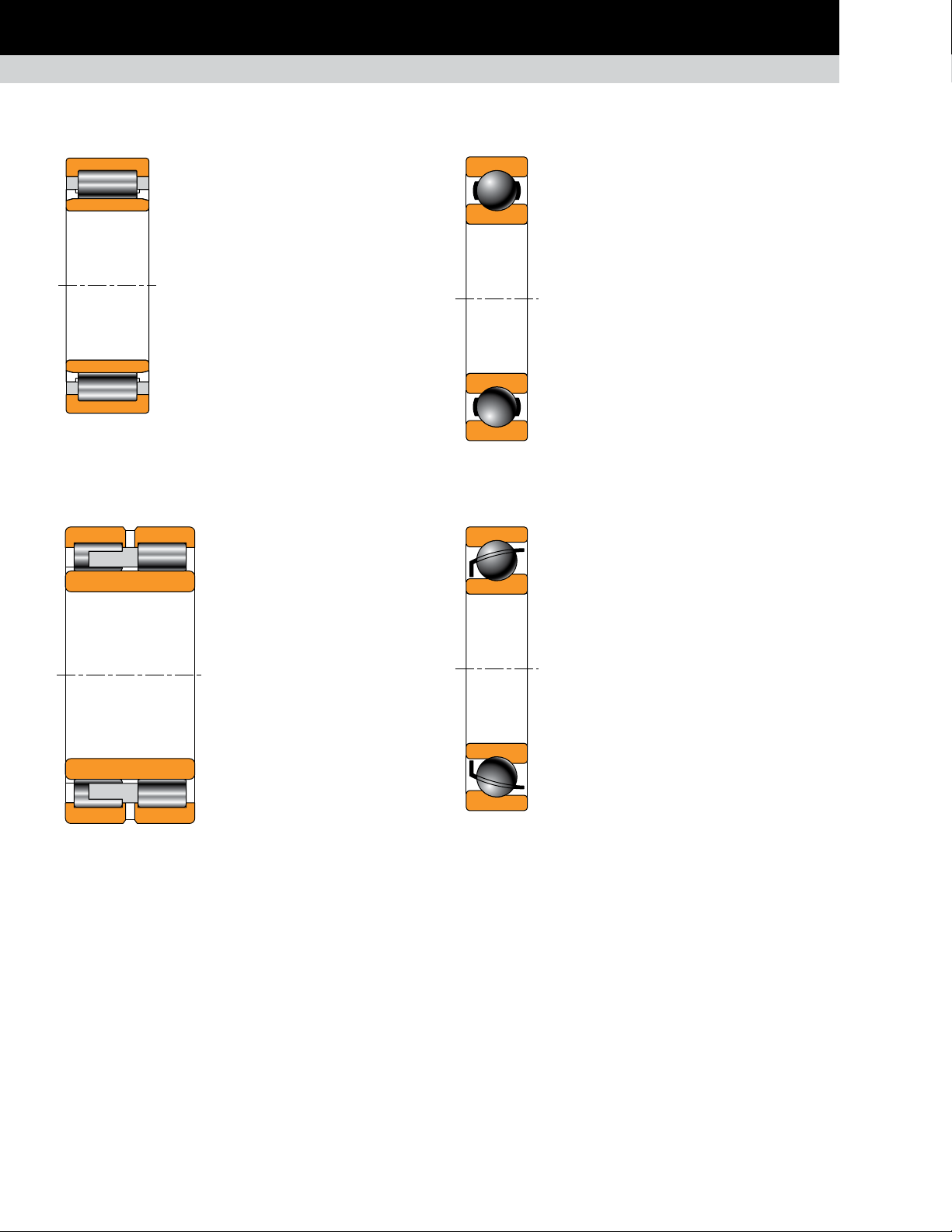
CYLINDRICAL ROLLER BEARINGS
ONE-ROW EMA TYPE
Composition: One single inner ring, one
single outer ring, one row of cylindrical
rollers with a one piece, land-riding
window-type brass cage.
Application: Gear drives, electric motors.
Remarks: Available in multiple configurations:
NU, N, NJ, NF and more.
Fig. 33. One-row
EMA type.
TWO-ROW CYLINDRICAL
ROLLER BEARINGS
Composition: One single inner ring,
one single outer ring, two rows of
cylindrical rollers with a one piece,
land-riding, finger-type brass cage.
Application: Gear drives, crop shear.
Remarks: Standard cage design
includes a drilled pocket, finger-style
brass retainer.
BALL BEARINGS
DEEP-GROOVE RADIAL
BALL BEARING
Composition: Inner and outer ring with a cage
containing a complement of balls.
Application: Gear drives, electric motors, fly
wheels and auxiliary equipment.
Remarks: The standard deep-groove
construction handles radial and light axial
loads for moderate- to high-speed applications.
Available in multiple configurations.
Fig. 35. Deepgroove radial ball
bearing.
ANGULAR-CONTACT
BALL BEARING
Composition: Inner and outer ring with a cage
containing a complement of balls.
Application: Work roll thrust position for long
product mill. Auxiliary equipment.
Remarks: Designed for combination radial and
axial loading. Single-row bearings have thrust
capacity in one direction. Typically used in pairs
to accommodate thrust in both directions.
Fig. 34. Two-row
cylindrical roller bearings.
20
TIMKEN ENGINEERING MANUAL
Fig. 36. Angularcontact ball bearing.
Page 23

APPLICATION CONSIDERATIONS AND BEARING SELECTION
APPLICATION
CONSIDERATIONS
AND BEARING SELECTION
The following processes are covered in this
section:
Steelmaking.
•
Continuous casting.
•
Rolling mill.
•
Flat product rolling.
•
Long product rolling.
•
Bearing solutions: radial positions.
•
Work and intermediate rolls: flat product mills.
•
Work rolls: long product mills.
•
Backup rolls.
•
Bearing solutions: axial positions.
•
Auxiliary equipment.
•
Main mill drive and pinion stand gearboxes.
•
Pay-off and rewind reels.
•
Shears and shear drives.
•
Table rolls.
•
TIMKEN ENGINEERING MANUAL
21
Page 24

APPLICATION CONSIDERATIONS AND BEARING SELECTION
STEELMAKING
The basic processes for the production of semi-finished and
finished products includes the following stages: mining the ore,
smelting, alloying, casting, rolling and finishing. Depending on the
metal type and production method, the processes used during
the smelting stage, where the metal is extracted from the ore,
can vary dramatically. After the smelting stage, the processes
for metals production have much more in common.
This section outlines the critical bearing applications used in the
metals production process after the smelting stage. Specifically,
it covers applications in basic oxygen furnaces (BOF) and
continuous casters used in steel production, as well as hot-rolling
and cold-rolling mills that can be used in the production of flat
and long metal products.
STEELMAKING
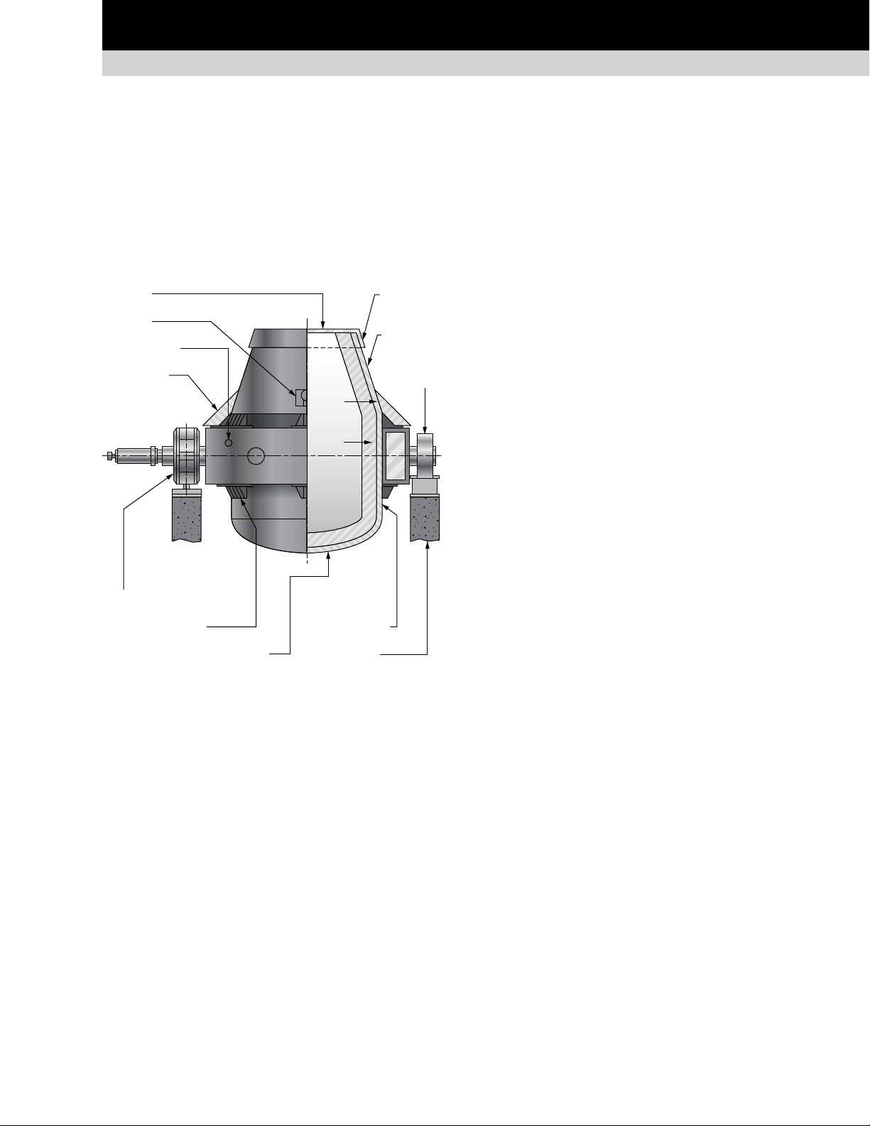
THE BASIC OXYGEN FURNACE
In the BOF (fig. 37) and the mechanically similar bottom-blown
oxygen process (BBOP) and argon-oxygen decarburization (AOD)
furnace, steel is melted for final alloy adjustment and purification.
The three furnaces are all types of converters. Each type has its
own configuration but they all are generally comprised of the
following equipment:
Furnace vessel. The furnace vessel usually resembles a
•
barrel-shape with a dished bottom and a conical top. The
inside includes a refractory material lining and a retractable
hood that closes off the top of the conical section.
Trunnion ring. A trunnion ring wraps around and supports
•
the vessel. The trunnion ring allows the vessel to tip
back and forth, pivoting on two stub shafts about 180
degrees apart.
Main support bearing and
housing assemblies
Drive assembly
Fig. 37. Basic oxygen furnace.
22
TIMKEN ENGINEERING MANUAL
Furnace vessel
Trunnion ring
Page 25
APPLICATION CONSIDERATIONS AND BEARING SELECTION
Top ring
Taphole
Trunnion ring
Slag shield
Nose (lip)
STEELMAKING
Main support bearings and housing assemblies. These
•
bearings come mounted to the stub shafts on the trunnion
ring and support the entire weight of the loaded furnace
and its drive.
Drive assembly. The drive assembly rotates the vessel
•
forward and backward from the vertical position through
approximately 135 degrees in each direction. In modern
vessels, a trunnion stub shaft supports the drive and a
torque arm anchors it to the foundations.
ring
Top cone
Float
bearing
Fixed bearing (drive side)
Support brackets
Torispherical bottom section
Fig. 38. Bearing support on basic oxygen furnace.
Barrel section
Support pier
Safety
lining
Working
lining
The second key bearing locations exist within the drive for the
BOF rotation. The drive is generally comprised of several smaller
enclosed gear reducers and motors mounted to a common
gear case that also enclose the bull gear. Each of the smaller
drive units has its own pinion that meshes with the bull gear.
Bearing selection for this application follows traditional power
transmission guidelines.
MAIN SUPPORT POSITIONS
The preferred bearing type for main support trunnion positions is
the spherical roller bearing due to its high-radial capacity, ability
to function as a fixed position bearing and high-misalignment
capability. Bearing selection is based primarily on static load
capacity because of the slow rotational speed. The target static
capacity-to-load ratio is 3:1 or greater. Typical sizes fall in the
range of 600 mm (23.62 in.) bore to 900 mm (35.43 in.) bore but go
as high as 1250 mm (49.21 in.).
We also must consider when establishing the bearing
requirements unique application conditions. These conditions
may include:
Structural deflections that may exceed ±1.5 degrees.
•
Very high loads at very low speeds and elevated
•
temperatures. This is particularly important in relation to
lubrication.
Oscillating motion through a maximum of 270 degrees of
•
rotation.
Significant axial growth of the trunnion ring due to
•
temperature changes over a large bearing spread up to
12 m (40 ft.).
There are two key positions for roller bearings in BOF applications.
The first and most challenging include the two main support
positions for the vessel and its trunnion ring (fig. 38). The second
lies within the drive.
The main support position bearings allow the vessel to tip forward
for raw material loading and for pouring out the refined steel.
The vessel tips backwards after the refined steel is poured off
(teemed) for slag removal. The melting completes with the vessel
in the vertical position. The combined weight of the vessel,
trunnion ring and the melt max exceed 1000 metric tons. In modern
designs, where the drive mounts directly to the trunnion support
shaft rather than to the foundation, the loads can approach 1500
metric tons.
Significant vibration from the agitation of the steel during
•
melting and from blowing oxygen through the liquid steel.
Vibration is particularly extreme in AOD furnaces.
Highly contaminated operating environments and the
•
resulting demanding sealing requirements.
Practical accessibility for inspection and future bearing
•
replacement.
For these applications and operating conditions, Timken suggests
using a complete bearing and housing system that is tailored
to the specific installation. This system generally includes two
housed assemblies – one for the float position and one for the
fixed position.
TIMKEN ENGINEERING MANUAL
23
Page 26
APPLICATION CONSIDERATIONS AND BEARING SELECTION
Ladder Bearing Arrangement
STEELMAKING
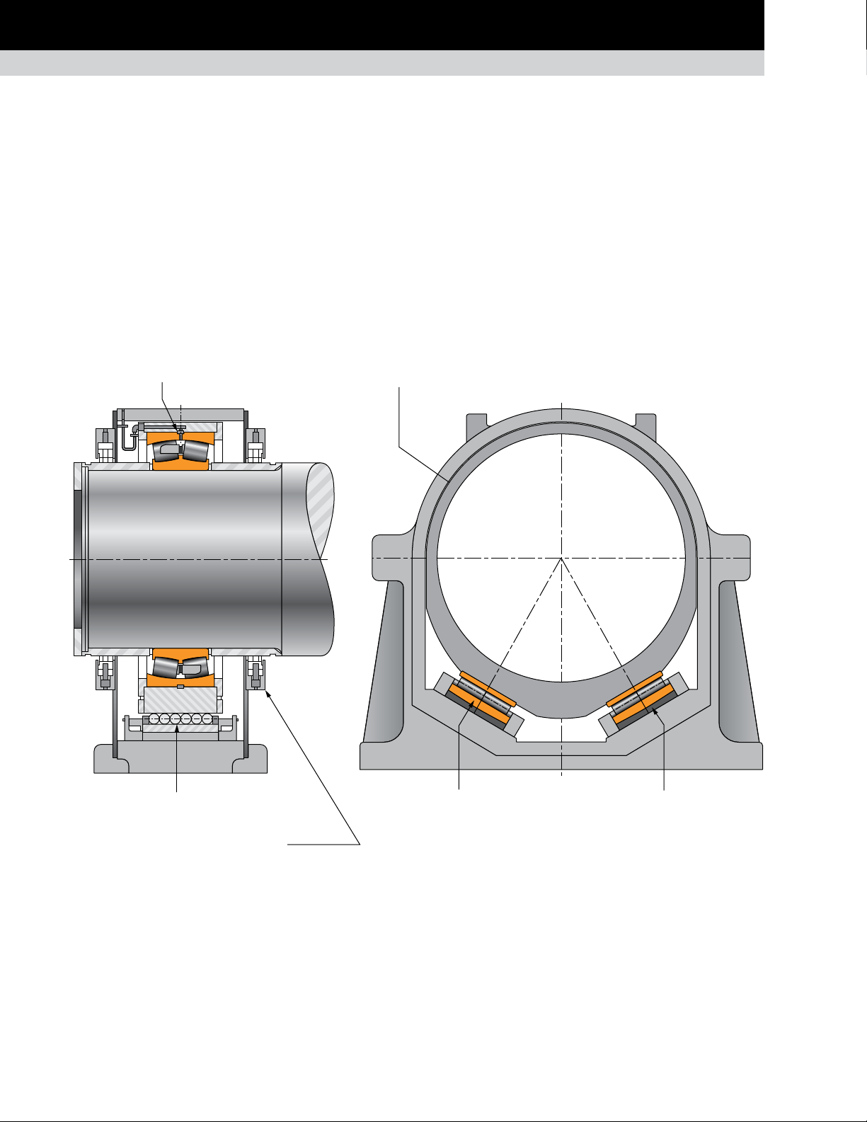
BOF trunnion float position
The float position assembly (fig. 39) generally mounts on the
non-driven side of the vessel and must accommodate several
centimeters (inches) of axial movement. The typical bearing
solution mounts the support bearing in a cartridge supported
on a pair of inclined linear bearings, often referred to as ladder
bearings (fig. 40).
The ladder bearings typically offer a float capability of ± 60 to
100 mm (2.5 to 4.0 in.) from its centered position. The static load
capacity of each ladder bearing approximately equals that of the
main support bearing.
FLOAT SIDE OF BOF HOUSING ASSEMBLY:
Full ring to contain radial bearing.
This design does not require the float bearing to move axially in
its housing. This eliminates the risk of galling and wear that can
occur on the bore or outer diameter surfaces when high radial
load forces the bearing to move. Ladder bearings are inclined
towards each other in a shallow V configuration to stabilize and
locate the cartridge in a crosswise direction.
The main support bearing generally has a loose fit on the trunnion
shaft and in the cartridge to facilitate installation and removal. The
floating cartridge assembly and ladder bearings mount in a fully
enclosed steel housing that also includes the main seals.
Bearing cartridge floats on ladder bearing to
accommodate thermal expansion.
Complete assembly installed as a unit;
all bearing areas completely sealed.
Fig. 39. Float side of BOF housing assembly.
Plain seatSpherical seat
Fig. 40. Ladder bearing arrangement.
24
TIMKEN ENGINEERING MANUAL
Page 27
APPLICATION CONSIDERATIONS AND BEARING SELECTION
Bearing with tapered bore and adapter sleeve.
STEELMAKING
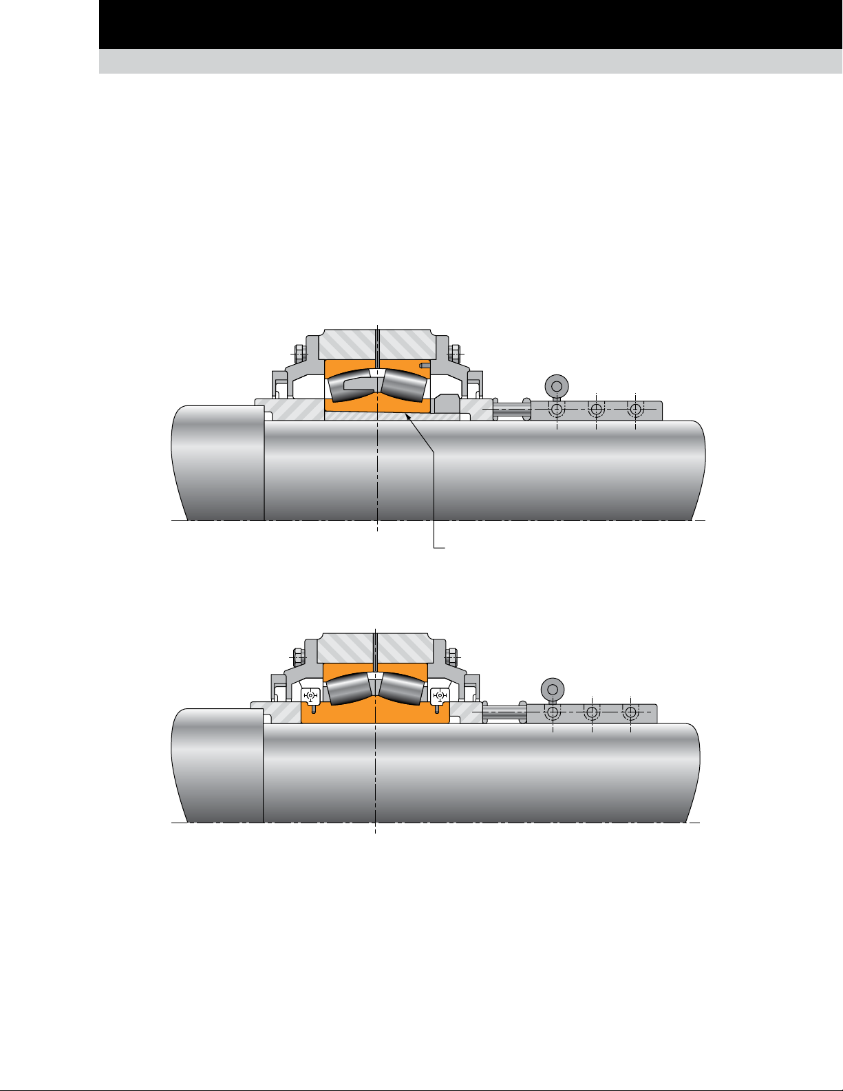
BOF trunnion fixed position assembly
The fixed position assembly is simpler and smaller because it
does not require the floating internal cartridge or ladder bearings.
The fixed position is usually on the drive side of the furnace. One
important design feature of the fixed position assembly involves
the ability to replace the original standard bearing (fig. 41) with
a split version (fig. 42). This proves necessary because the
replacement of a standard bearing would require the removal
of the complete drive assembly. This is a difficult and very timeconsuming task.
FIXED SIDE OF BOF HOUSING ASSEMBLY:
Initial mounting of standard bearing is done in one of two ways.
Either mount a straight bore bearing directly to the shaft using a
tight fit; or mount a tapered bore bearing using a tapered adapter.
The use of the adapter allows final control of the bearing
position on the shaft and some adjustment of the bearing
internal clearance. The adapter also facilitates bearing removal
through the use of hydraulic pressure that frees the bearing from
the adapter.
Fig. 41. Standard bearing.
Fig. 42. Split bearing.
Bearing with tapered bore and adapter sleeve.
TIMKEN ENGINEERING MANUAL
25
Page 28

APPLICATION CONSIDERATIONS AND BEARING SELECTION
STEELMAKING
The use of a split replacement bearing facilitates removal of the
standard bearing. First remove the housing cap, slightly raise the
trunnion shaft, then remove the standard bearing by cutting or
fracturing it into halves. If a tapered adapter was used, remove
it in the same manner. An axial slot in the adapter-bore facilitates
burn off without trunnion shaft damage. The new split bearing
builds up around the shaft before lowering back down into
the housing.
The tight-fitted adapter helps reduce the risk of impact damage
to the bearing components due to potentially violent vibration of
the vessel during operation.
Spherical roller bearings used in BOF housings have a standard
misalignment capability of 1.5 degrees. When higher misalignment
is required, the bearing may be supplied with a wide outer ring
that increases the misalignment capability to 3 degrees. Timken
identifies bearings with this feature using W57 in the part number.
Timken usually supplies assemblies with sleeves located on the
trunnion shaft on both sides of the bearing. The backing sleeves
facilitate axial clamping of the complete assembly onto the shaft
and function as seal riding surfaces. When installing a split
bearing, replace these sleeves with narrower versions to make
room for the wider inner ring.
Because BOF bearing assemblies must function in the dustcontaminated and often hot environment of a steel mill, effective
sealing is critical. Bearings subjected to contamination by
abrasive converter dust may suffer premature wear. To help
prevent this, robust sealing accommodates the displacement
of the shaft that results from trunnion ring thermal growth
and deflection.
Additional considerations for trunnion
bearing selection
Furnaces must tolerate the significant and sometimes violent
vibration that occurs during furnace charging, melting and
purification. Consider these factors during the design and
selection of bearings and housings. For optimal bearing
performance, we prefer light-to-tight bearing fits on the shaft
and in the housing. However, it also is important to consider the
ease of installation and removal.
Minimized bearing radial clearance limits risks of fretting
corrosion (false brinelling) of the rollers and raceways. Minimizing
operating clearances and applying light-to-tight fits also improves
the seating of the bearing’s inner and outer rings and maximizes
the load zone within the bearing. These bearings are traditionally
through-hardened but Timken also offers the bearings with casecarburized components for applications where shock loading is
a particular concern.
In this application, the lubricant primarily functions to help prevent
corrosion and to help keep contaminants out. To achieve this,
we suggest 100 percent grease fill of the bearing and housing
cavity. These furnaces use an extremely slow rotational speed.
Rollers and raceways cannot generate a normal lubricant film.
A heavy consistency, extreme-pressure (EP) grease with a very
high base-oil viscosity can improve lubrication conditions. We
suggest synthetic base oil, lithium complex types.
Timken also manufactures split and special bearing designs and
can review your specific application needs. For more details,
contact your Timken engineer.
26
TIMKEN ENGINEERING MANUAL
Page 29

APPLICATION CONSIDERATIONS AND BEARING SELECTION
CONTINUOUS CASTING
The continuous caster for producing steel slabs (fig. 43), blooms
and billets represents the most significant development in steel
production since the Bessemer converter. Compared to the
traditional, individually poured cast ingot route, the continuous
caster offers significant improvements in yield, consistency
and energy efficiency as well as reduced emissions and
waste products. In addition, the ability to cast thinner slabs
(alloy dependent) may significantly reduce the subsequent hot
rolling requirements.
Generally, the conventional slab caster produces slabs between
180 mm (7 in.) and 300 mm (12 in.) thick at speeds of 0.8 to
2.0 m/min. (2.6 to 6.5 ft./min.). The medium slab caster produces
slabs between 100 mm and 180 mm (4 and 7 in.) thick at speeds of
1.0 to 3.0 m/min. (3.3 to 10 ft./min.). The thin slab caster produces
slabs less than 100 mm thick at speeds of 3.0 up to 6.0 m/min. (10
to 20 ft./min.).
CONTINUOUS CASTING
Fig. 43. Typical continuous slab caster layout.
TIMKEN ENGINEERING MANUAL
27
Page 30

APPLICATION CONSIDERATIONS AND BEARING SELECTION
CONTINUOUS CASTING
CASTER DESIGN
Fig. 44 shows the main components of the continuous caster. Nearly all installations possess this overall configuration, although minor
variations will exist depending on the original equipment manufacture's technology, steel grade being cast, and end-user preferences.
The following description refers to slab casting but bloom and billet casters can receive similar considerations.
Foot rolls
Bender section
Fig. 44. Continuous slab caster schematic.
Horizontal withdrawing section
SEQUENCE OF OPERATIONS
First, molten steel transfers from the steelmaking furnace to the
casting platform in a ladle.
Then the ladle pours the molten steel into the tundish through
a shroud.
Another shroud takes the molten steel into the water-cooled mold.
The mold lining, typically comprised of a copper alloy, oscillates
to minimize the chance of the steel sticking to the mold. The steel
solidifies at the surface to form its shape (slab, billet or bloom)
before it emerges from the mold, attached to the dummy bar. The
dummy bar detaches at the exit end of the caster.
Once the slab leaves the mold, it proceeds through the top
zone (foot rolls) via the bender to the curved (bow) section
through a straightener section and finally to the horizontal
withdrawal section.
A straight-mold equipped caster includes a bender section that
forms the slab to match the curvature of the bow section. Casters
with a curved mold do not require the bender.
Bow section
Straightener section
Below the mold, caster sections break down into eight to 12
discrete segments, each with five to seven roll pairs with one roll
of each pair above and one below the slab. One of the roll pairs
is a driven pair that controls the speed of the slab. The other,
idler rolls, support the slab and maintain its thickness and shape.
Many casters will make a small reduction in the slab thickness as
it descends through the bow section. This is referred to as soft
core reduction and is done for metallurgical reasons rather than
for slab thickness control.
The top and bottom rolls are mounted on two separate frames and
adjustment is provided to allow setting the position of the top rolls
relative to the bottom rolls. Each of the individual roll segments
can be removed from the caster as a complete assembly.
External, high-volume water sprays cool the slab. The
support rolls also are water cooled via rotary couplings and
internal passages. Cooling the rolls and bearing housings
controls component temperature and the integrity of their
mechanical properties.
After the slab exits the straightener segment(s) it passes through
the horizontal withdrawal segments and is cut to length with a
traversing gas torch. Finally, the slab is brought to a cooling yard
where it is marked before being transferred to the hot rolling mill.
28
TIMKEN ENGINEERING MANUAL
Page 31

APPLICATION CONSIDERATIONS AND BEARING SELECTION
CONTINUOUS CASTING
CASTER BEARING POSITIONS
LADLE TURRET
The rotating portion of the turret, supports the main bearing
application in the ladle turret.
Mould and
Ladles
Fig. 45. Typical ladle turret layout.
Tundish
Ladle turret bearings
The bearings must resist very high overturning moments resulting
from the cantilevered loads. The highest overturning moments
occur when one side supports a full ladle while the other side
is empty. They also must tolerate shock loads that occur when
a full ladle is loaded onto the support arms. The total weight of
the ladle turret, ladles and molten steel can exceed 1000 metric
tons, while the rotational speed reaches no more than 1 rev./min.
Two turret design styles exist. The first (fig. 45) uses a single
turntable attached to both support arms. The turntable is mounted
onto a large-diameter slewing ring bearing that can measure
several meters in diameter. This is the most common design.
The second design utilizes a central column, or mast, around
which sleeve-attached support arms rotate around the center
column on radial and thrust bearings. This style can be configured
to accommodate independent rotation of each ladle support arm.
oscillator
assembly
Rotating
turret
MOLD OSCILLATOR
Oscillating the mold is critical to help minimize the sticking of the
steel to the mold liner. Early caster styles achieved this oscillation
through mechanical mechanisms using cams or eccentrics and
an electric motor drive. Hydraulic resonant oscillators replaced
most of these designs because they provide a more compact
design and control flexibility. The hydraulic design also eliminates
mechanical drive components that can wear quickly and require
frequent maintenance.
Mold oscillator bearings
Casters that use mechanical oscillators require bearings
specifically designed to handle the oscillating loads and
vibrations. Cylindrical, spherical and tapered roller bearings
commonly meet this need. They are generally specified with
high-strength cages and are manufactured with tight control of
internal clearances and run-out.
FOOT ROLL (TOP ZONE) AND
BENDER SECTIONS
This is the first section of slab support rollers directly beneath
the mold. The skin on the slab is thin and fragile so the support
rollers are close together and small in diameter. These rolls are
usually in the range of 120 to 160 mm (4.7 to 6.3 in.) in diameter
and are idler (non-driven) rolls.
Roll construction utilizes a single, full-width arbor/axle built up
with roll section sleeves and intermediate support bearings. More
commonly, roll construction consists of individual roll sections,
each with a support bearing at both ends. These rolls utilize
external cooling with water sprays.
Caster bearings endure tough conditions in this environment,
including heavy loads, high temperatures, low rotational speed as
well as water, scale and steam contamination. The slab surface,
which passes just a few millimeters (a fraction of an inch) from
the bearing housing, reaches approximately 1000° C (2000° F).
Bearing types used in the mast-style ladle turret will vary
according to the original equipment manufacturer. Generally,
cylindrical roller bearings provide radial support and a dedicated
thrust bearing provides the axial support. This thrust bearing can
utilize a tapered-, spherical- or cylindrical-roller type.
TIMKEN ENGINEERING MANUAL
29
Page 32

APPLICATION CONSIDERATIONS AND BEARING SELECTION
CONTINUOUS CASTING
Foot roll section and bender bearings
Due to these extreme conditions, bearings located at foot roll (fig.
46) and bender roll positions are usually removed from operation
on a fixed schedule rather than on the basis of their condition at
inspection. Replacement typically occurs every four to six months.
Sealing is usually achieved with the use of steel spiral rings or
piston rings since the temperatures are too high for elastomeric
seals. A continuous grease lubrication is typically used to keep
contaminants from entering into the bearing.
Bearing types used here include single- and double-row needle
roller bearings in the NA49, NA59 and NA69 series, as well
as spherical roller bearings and cylindrical roller bearings of
the toroidal or self-aligning type. Our specially heat-treated
bearings offer dimensional stability during operation at elevated
temperatures. These bearings are usually identified with a S2 or
S3 as the suffix to the part number. This identifies the bearings
as being dimensionally stable at temperatures up to 250° C and
300° C (482° F and 572° F) respectively.
Bearing loads in these applications vary by the number of rolls,
the number of bearings per roll, roll position and the ferro-static
pressure within the slab. Speeds often fall in the range of 2 to
15 RPM, depending on the thickness of slab being cast. The low
rotational speed means that loading is considered static because
a hydrodynamic lubricant film generates outside the rollers and
the raceways of the bearing. The bearing’s static capacity is,
therefore, more important than the dynamic capacity. Generally,
bearing selection revolves around a static capacity-to-load ratio
of 3:1. However, the frequent replacement of the bearings means
that many installations operate with a ratio of 2:1. This need for
frequent maintenance, combined with low speeds prompt loose
fits for both the inner and outer rings.
SLAB SUPPORT SEGMENTS (BOW,
STRAIGHTENER AND HORIZONTAL SECTIONS)
The slab support segments in the bow, straightener and horizontal
sections of the caster all possess similar configurations, but with
variations in the number of rolls and the roll diameters. Segment
configuration provides for easy removal and replacement as
complete assemblies.
The shell of the slab gets thicker as the slab moves down the
caster, with complete solidification occurring somewhere in the
lower half of the bow section. This means that the slab support
rollers can be placed further apart and can be larger in diameter
than those at the top of the caster. The number of rolls in each
segment varies from 10 to 14, arranged in pairs, with one roll of
each pair above and one beneath the slab.
Drive roll
Segmented idler rolls
Fig. 47. Typical roll configuration.
Generally, the center pair of rolls drives and controls the speed of
the slab through the caster (fig. 47). The remaining rolls are idler
rolls. The loading on the segment rolls in slab casters requires
intermediate support bearings along their lengths to minimize the
roll deflection. Slab quality demands this key parameter.
Fig. 46. Typical foot roll bearing arrangement.
30
TIMKEN ENGINEERING MANUAL
The idler support rolls often include two or three short roll sections
with each section having a bearing at either end. These rolls utilize
internal cooling and use rotary couplings to bring the cooling
water to and from the rolls.
Staggered positions of the intermediate bearings fall in the
direction of material travel. This minimizes the effects to the
unsupported portion of the slab where it passes over the bearings
and housings.
Page 33

APPLICATION CONSIDERATIONS AND BEARING SELECTION
CONTINUOUS CASTING
Slab support segment bearings
Bearing selection and mounting must allow for one fixed and one
or more float positions for each roll section. The spherical roller
bearing usually achieves the fixed position selection.
The float position bearings must accommodate up to 6 mm (0.25 in.)
of roll thermal-axial growth and up to 0.5 degrees misalignment.
Float position solutions include self-aligning cylindrical bearings,
toroidal roller bearings or Timken
that combine the characteristics of both spherical and cylindrical
roller bearings. These designs will accept axial float within
the bearing as well as higher misalignment than a standard
cylindrical bearing.
The spherical roller bearing also applies at the float position,
but in this case, loose fits are employed for the outer ring to
accommodate float in their housings.
®
ADAPT™ bearings (fig. 48)
Casters may use idler rolls that use a single, full-width arbor
(shaft) and roll section sleeves. We may refer to this style as a
stacked-arbor design (fig. 49). This stacked-arbor style uses a
single bearing in the intermediate support position that reduces
the width of an unsupported slab compared to the two bearings
required with completely separate roll sections.
The bearing installation will usually follow standard fitting
practice guidelines. Avoid heavy-duty tight fits because they
complicate installation and removal and increase the risk of
damaging the bearing during removal. In the case of spherical
roller bearings, use C3 and C4 prevalent radial internal clearance.
For conventional (non-split) bearings, we suggest g6 or f7 shaft
fits and G6, G7 or H7 housing fits.
Fig. 48. The design of the ADAPT™ bearing allows for
simultaneous axial float and misalignment. The rollers align with
the inner ring regardless of axial displacement and misalignment.
Fixed position
Intermediate support position
spherical roller bearing
Fig. 49. Stacked arbor schematic with ADAPT bearing.
ADAPT™
(if applicable)
Float position
ADAPT
TIMKEN ENGINEERING MANUAL
31
Page 34

APPLICATION CONSIDERATIONS AND BEARING SELECTION
CONTINUOUS CASTING
The drive roll needs the intermediate support bearing(s) and
needs to transmit drive torque across the full width. The
traditional design achieves this with a one-piece roll with split
bearings located at one or two positions (fig. 50). The bearing and
housing assembly used in a one-piece roll design are split for
mounting purposes.
These split bearing assemblies can utilize either spherical (fig.
51) or cylindrical roller bearing assemblies.
Split assemblies are usually designed as a complete system with
the bearing and housing designed together to suit a particular
caster roll configuration. Special bearings are required that do not
conform to International Standard Organization (ISO) envelope
dimensions or tolerances. Spherical assemblies require a loose
shaft fit to allow axial float of the shaft. Cylindrical assemblies can
use a transition fit on the shaft. Use loose housing fits for both the
cylindrical and spherical roller bearing assemblies.
These assemblies must utilize split elements, including the
bearing inner and outer rings, cages (when used), seals and the
housing itself. Just like the conventional bearings and one-piece
housings used in the end positions, the assemblies used here
must also allow for water cooling of the housing caps and grease
supply to the bearing.
Common key features to both spherical and cylindrical roller
bearing types include the half outer ring, water-cooled housing
cap and triple or double sealing elements. Timken uses a patented
serpentine cooling chamber (fig. 52) in the cap to optimize the
coolant velocity for maximum heat removal and minimum scale
build up.
Axial float
clearance
Fig. 50. Solid drive roll with split intermediate bearing.
Fig. 51. Split spherical roller
bearing and water-cooled
housing.
32
TIMKEN ENGINEERING MANUAL
Fig. 52. Patented serpentine
cooling chamber.
Page 35

APPLICATION CONSIDERATIONS AND BEARING SELECTION
ROLLING MILL
ROLLING MILL
FLAT PRODUCT ROLLING
While there will be variations to the product flow resulting in cold
rolled strip, the process flow generally begins with material that
either comes from a continuous caster, slabbing mill or directly
from an ingot. In this section, we focus on the bearings and their
relationship to the rolls they support (fig. 53).
The rolling mill is an extremely demanding application for
bearings, which must perform under high operating temperatures,
loads up to 8000 metric tons for the heaviest plate mills, and linear
speeds in excess of 2000 m/min. (6500 ft./min.) for the fastest
cold mills.
Screwdown
In addition, instantaneous changes in speed and direction can
create punishing combinations of radial and thrust loads. When
choosing a bearing for your rolling mill application, you must
consider all operating parameters.
Several significant differences exist between hot rolling and
cold rolling:
Mill speeds are significantly higher in cold rolling than hot
•
rolling.
The strip exiting the cold mill is controlled to much tighter
•
tolerances and higher surface quality.
The cold mill will typically have extended run times during
•
operation relative to the hot mill, particularly when the
design of the mill calls for continuous operation, where coil
ends are joined together upstream; or in foil mills, where
final passes through the mill may last several hours.
Backup roll position
Work roll position
Driven side
Fig. 53. Rolling mill applications 4-Hi mill stand.
Operator side
TIMKEN ENGINEERING MANUAL
33
Page 36

APPLICATION CONSIDERATIONS AND BEARING SELECTION
ROLLING MILL
PLATE MILL AND HOT MILL ROUGHING STANDS
Roughing stands are used for rolling heavy slabs supplied from a
slabbing mill, continuous caster or sometimes rolled directly from
an ingot. Finished material thickness varies greatly in dimensions.
Mills can roll plates above 200 mm (8 in.) thick, 5 m (197 in.) wide,
and 35 m (115 ft.) long. These three dimensions are determined by
the slab or ingot weight as well as the rolling mill’s size.
Mill speed: less than 300 m/min. (1000 ft./min.)
Roll neck bearings:
Backup roll radial position:
•
TQOW, 2TDIW, mutli-row cylindrical (RX), oil-film bearings
Backup roll thrust position:
•
TDIK, 2TSR required with cylindrical bearing and
oil-film bearings
Work roll radial position:
•
TQOW, 2TDIW
Work roll axial position:
•
TDIK, 2TSR (in case of axial shift)
HOT MILL
Hot rolling is primarily intended to reduce the thickness of the
material that leaves the roughing stand or the continuous caster.
In modern hot strip mills, the dimensional control of the finished
strip is critical and affected by important strip characteristics
such as thickness, profile and flatness. The product from the
finishing stands is coiled and, subsequently used as feed stock
for cold rolling or used directly by fabricators.
Mill speed: generally less than 1000 m/min. (3300 ft./min.)
Roll neck bearings:
Backup roll radial position:
•
TQOW, 2TDIW, multi-row cylindrical (RX) or oil-film bearings
Backup roll thrust position:
•
TDIK, 2TSR, TTDWK required with cylindrical and
oil-film bearings
Work roll radial position:
•
TQOW, 2TDIW
Work roll axial position:
•
TDIK, 2TSR (in case of axial shift)
COLD MILL
The cold rolling process, unlike hot rolling, deforms metal at
temperatures below its recrystalization temperature. This results
in cold working of the material and an increase in its strength and
hardness. While cold rolling increases the hardness and strength
of a metal, it also results in a large decrease in ductility. Therefore,
most ferrous products exiting the cold mill must go through both
annealing (heating) and temper rolling operations.
Mill speed: 1000 m/min. (3300 ft./min.) to above 2000 m/min.
(6500 ft./min.)
Roll neck bearings:
Backup roll radial position:
•
Multi-row cylindrical (RX), TQIT or oil-film bearings
Backup roll thrust position:
•
TDIK, 2TSR required with cylindrical and oil-film bearings
Work roll radial position:
•
TQOW or 2TDIW
Intermediate roll radial position:
•
TQOW or 2TDIW
Work roll and intermediate axial positions:
•
TDIK, 2TSR (in case of axial shift systems)
TEMPER MILL
The temper mill, also referred to as skin-pass mill, is a cold rolling
mill used for tempering the strip by making a small thickness
reduction (about two percent). The design of the rolling mill can
be 2-Hi, 4-Hi or 6-Hi. The physical properties that are enhanced
by the temper pass due to slight elongation of the product include:
Dimensional trueness and repeatability,
Suppression of yield point elongation,
Improved surface finish, and
Improved shape and flatness.
Mill speed: generally <1200 m/min. (3950 ft./min.)
Roll neck bearings:
Backup roll radial position:
•
Multi-row cylindrical (RX), TQIT
Backup roll thrust position:
•
TDIK, 2TSR required with cylindrical
34
TIMKEN ENGINEERING MANUAL
Work roll radial position:
•
TQOW, 2TDIW
Intermediate roll radial position:
•
TQOW, 2TDIW
Page 37

APPLICATION CONSIDERATIONS AND BEARING SELECTION
ROLLING MILL
LONG PRODUCT ROLLING
The long products description applies to a wide variety of semifinished and finished products. These include round, rectangular
and hexagonal bar, seamless and welded tubes, structural
sections such as channels and beams, rails, rod and wire.
Despite the wide range of products, the overall process is similar
to that for flat products. The starting point is a cast billet, bloom or
cast bloom that is processed through roughing and finishing mills
using both hot and cold rolling. After rolling the product moves on
to finishing operations such as straightening, reeling and sizing.
The wide range of long products is reflected in the many styles
of rolling mills used by their manufacturer. They include, but are
not limited to:
2-Hi and 3-Hi reversing bar mills.
•
Multi-stand 2-Hi bar mills with overhung (cantilevered) rolls.
•
Piercing and sizing mills with inclined rolls for
•
seamless tube.
Forming and welding lines for welded tube.
•
Universal mills combining horizontal and vertical rolls for
•
sections and rails.
Like flat product mills, these are extremely demanding
applications for the rolling mill bearings. In addition, the rolling
of asymmetrical shapes can introduce axial loads that are higher,
relative to the radial loads, than seen in flat product mills. For
this reason the roll neck bearing configuration (fig. 54) usually
includes a separate thrust bearing.
Roll neck bearing selection criteria are similar to those for flat
products but the variety of mill types and designs means that there
will be variations, due to dimensional constraints.
High-speed, multi-stand mills for rod and wire products.
•
Fig. 54. Typical roll and bearing arrangement for a bar mill.
TIMKEN ENGINEERING MANUAL
35
Page 38

Negative roll bending
b
O.D.
b
APPLICATION CONSIDERATIONS AND BEARING SELECTION
BEARING SOLUTIONS: RADIAL POSITIONS
BEARING SOLUTIONS:
RADIAL POSITIONS
WORK AND INTERMEDIATE ROLLS:
FLAT PRODUCT MILLS
Work roll bearings have a smaller section height and a much
narrower width than a backup roll bearing (see page 46 for
backup roll solutions), because loads are significantly lower at
this position.
The work roll bearing is sized as a function of the work roll’s
neck and body diameters. The neck diameter is influenced by
the coupling diameter necessary to transmit the required torque.
The shape of the strip’s cross-sectional profile can be adjusted
dynamically by shape (or flatness) control systems. These
systems adjust the shape of the roll gap across the mill width,
such that flat strip can be produced. The need for closer
tolerances, improved strip flatness and increased productivity
all put increased demands on the work roll bearings. Several
of the techniques used for controlling strip flatness are
discussed below.
The roll bending technique induces significantly higher radial
loads on the work roll bearings than are seen in conventional
mill stands. Bending loads (per chock) in excess of 80 metric
tons on cold mills and above 200 metric tons on hot mills are
typical. These higher loads combined with smaller chock
sections require careful consideration. A Finite Element Analysis
(FEA) of the chock/bearing system may be needed in order to
validate the catalog L
deformation resulting from the high applied loads. An example
of how the loading may be distributed among the rollers around
the circumference of the bearing is illustrated below (see fig. 56).
This load distribution often is referred to as rabbit ears – where
the roller loading at the center of the load zone is lower than at
the adjacent quadrants where the chock section is larger.
life calculation due to the chock bore
10
FLATNESS CONTROL TECHNIQUES
Roll bending: Roll bending was first introduced as a means of
improving the strip profile and flatness. Later, roll bending (fig.
55) was introduced to hot strip mills to improve upstream product
quality (profile).
Separating force
Positive roll bending
Fig. 55. Roll bending.
Fig. 56. Rabbit ears shaped roller load distribution.
These analysis have shown that both vertical and horizontal
chock sections (a and b) in fig. 57 are critical to chock deflection
and bearing performance.
a
a
a = 0.0625 x bearing O.D.
Bearing
Fig. 57. Work roll chock sections (symmetrical chock).
Axial roll shifting and roll crossing: Roll shifting can be used in
addition to roll bending to further increase control of the roll gap
profile. Axial roll shifting (fig. 58) combined with a special roll body
profile is used to change the shape of the effective roll gap. Roll
shifting is generally applied without loads to the work rolls of a
4-Hi mill or to the intermediate rolls of 6-Hi mills.
b = 0.1 x bearing O.D.
36
TIMKEN ENGINEERING MANUAL
Page 39

Bearing O.D.
Minimum roll diameter
Minimum roll diameter
Bearing O.D.
APPLICATION CONSIDERATIONS AND BEARING SELECTION
BEARING SOLUTIONS: RADIAL POSITIONS
In roll-crossing systems (fig. 59), additional mechanical actuators
displace the roll ends in opposite directions in the horizontal plane
resulting in crossing of the rolls. This crossing also results in a
change of the effective roll-gap profile.
Both of these flatness control systems generate higher roll thrust
loads than are seen in a conventional mill stand and typically
require a separate thrust bearing. With this configuration,
radial loads are absorbed strictly by the four-row bearing, while
the thrust loads are absorbed by the thrust bearing. There are
exceptions where relatively steep angled four-row tapered roller
bearing (TQOW type) assemblies accommodate both the radial
and axial loads. However, these exceptions require detailed
analysis to ensure appropriate bearing selection.
Thrust bearing selection is discussed later in this chapter.
Bearing O.D. per chock section requirement: Work roll bearing
selection requires careful analysis of the space available
between the mill pass line and the backup roll chock. The
minimum radius of the work roll body must exceed the height of
the work roll chock from the chock’s center-line to the pass line
to ensure roll contact without chock interference.
The work roll chocks are either symmetrical (fig. 60) or
non-symmetrical (fig. 61) versus the chock’s center-line. The
non-symmetrical chock (with a smaller section height toward
the pass line) allows for a smaller minimum work roll O.D. for the
same bearing O.D.
Pass line
Ka
Kb
Fig. 58. Axial roll shifting.
Fig. 59. Cross rolling.
BEARING SELECTION: DIMENSIONAL CRITERIA
Work roll: The size of the work roll bearing assembly is
constrained by the roll neck diameter, the chock outside
dimensions, and the position of the balancing and bending
cylinders. These constraints will limit the minimum allowable
bearing bore, the maximum allowable outside diameter (O.D.)
and the proper position of the bearing rows.
Bearing bore per roll neck size requirement: The neck diameter
can vary greatly according to the material used for the rolls. The
neck-to-barrel ratio range is approximately 45 to 50 percent for
cold mills where steel rolls are used and approximately 55 to
60 percent for hot mills where various grades of cast iron rolls
are used.
Minimum roll diameter = 1.125 x bearing O.D. + 2 mm (0.078 in.)
Ka (min.) = Kb (min.) = 0.562 x bearing O.D.
Fig. 60. Symmetrical work roll chock.
Pass line
Ka
Kb
Minimum roll diameter = 1.100 x bearing O.D. + 2 mm (0.078 in.)
Ka (min.) = 0.550 x bearing O.D.
Kb (min.) = 0.575 x bearing O.D.
Fig. 61. Non-symmetrical work roll chock.
TIMKEN ENGINEERING MANUAL
37
Page 40

APPLICATION CONSIDERATIONS AND BEARING SELECTION
BEARING SOLUTIONS: RADIAL POSITIONS
UNSEALED ROLL NECK BEARINGS
The four-row tapered roller bearing, TQOW type or 2TDIW type,
is the preferred solution for flat product work and intermediate
rolls as it offers many advantages:
Unitized construction, once assembled in the chock,
•
facilitates installation and removal from the roll neck.
Rolling elements are protected against handling damage
•
during chock removal and installation on the roll neck.
Ability to handle both axial and radial loads simultaneously.
•
A separate thrust bearing is typically not required.
The bearing’s internal clearance can be reset, if necessary,
•
after a period of use by regrinding spacers.
2TDIW with reduced axial tolerances enables more
•
compact and simpler mounting arrangements without
adjustable retaining system (see fig. 62).
Fig. 62. 2TDIW simplified mounting arrangement.
Bearing types: Many existing mills have been designed with
steeper angle work roll bearings compared to the backup roll
bearings to cope with axial loads caused by poor mill alignment.
This situation may be encountered in older mills with worn chocks,
housings and liners. Although steeper angle designs increase the
bearing’s thrust capacity, the radial capacity is reduced.
Type 2TDIW without cone spacer: Simplest and most compact
design. Tighter width tolerances allow simplified mounting
arrangement (fig. 62).
Type 3TDIW: The six-row tapered roller bearing also can be
considered in order to achieve an even higher radial capacity
when the bearing’s cross section is particularly constrained.
Six-row bearings are in use on the work rolls of some hot and
cold aluminum mills and also are designed into 4-Hi steckel mill
work rolls.
Type extra-wide 2TDIW: Extra-wide central cone and cup
spacers (fig. 63) are provided to separate the inboard two rows
from the outboard rows where roll shifting causes the radial load
from the bending cylinders to shift with respect to the bearing
center-line. The wide spread allows for improved distribution of
load among the four rows.
Fig. 63. 2TDIW extra wide.
Extended ribs for added sealing (TQOWE or 2TDIWE): The
space necessary for an integral seal often requires a slight
decrease in bearing rating due to the seal’s space requirement.
An alternative to avoid any capacity decrease is to install, at the
original equipment manufacturer's stage, a four-row bearing
with extended small ribs on the double cones (fig. 64). Here,
the chock seal rides on the plunge-ground surface of these
extended ribs and provides a more efficient chock-bearing sealing
system. In addition to improved sealing, this configuration also
protects the seal from potential damage during chock assembly
and disassembly.
Type TQOW: Widely used in the work roll position. This bearing
consists of two double cones, two single cups and one double
cup. The two cup spacers and hardened cone spacer are needed
to establish internal clearance at the factory.
Type 2TDIW with cone and cup spacers: Similar to the above
TQOW arrangement, but with the double cup replaced by two
single cups.
38
TIMKEN ENGINEERING MANUAL
Fig. 64. TQOWE extended ribs.
Page 41

APPLICATION CONSIDERATIONS AND BEARING SELECTION
BEARING SOLUTIONS: RADIAL POSITIONS
SEALED ROLL NECK BEARINGS
Sealed roll neck bearings are popular due to the need to reduce
costs associated with grease consumption and disposal,
simplifying bearing maintenance and maximize bearing life. The
sealed roll neck bearing does not require regreasing at each
roll change, allowing for cleaner mills and less contamination
of roll coolants.
In addition to reduced contamination and improved lubricant
retention, enhanced greases have been developed. These
greases can further improve bearing performance. The sealed roll
neck bearing is available non-greased or pregreased with one of a
range of enhanced mill greases to suit your particular application.
The space requirements for the seal are kept to a minimum in
order to maximize the bearing’s capacity. Timken sealed roll neck
bearings typically have the same capacity as the equivalent sized
open bearing (see product tables for further details).
The benefits of using sealed roll neck bearings include:
Reduced risk of contamination ingress and related damage,
•
which increases bearing reliability and life.
Minimized maintenance costs through reductions in grease
•
consumption and disposal charges.
Reduced risk of strip staining and rolling solution
•
contamination.
Extended maintenance intervals reducing the number of
•
inspections required per year.
Reduced grease contamination of cooling water and/or
•
rolling solution resulting in cleaner environment.
Integrated seal design
The integrated configuration features two main seals that are
mounted within counterbores in the extended outer cups. The
integrated seal design (fig. 65) is typically supplied according to
the configuration below.
The main seal lip rides on the extended cone small rib
and functions to exclude contaminants and retain grease
(fig. 66).
The bore seal (fig. 67) is a static seal that prevents ingress of
rolling solution from the cone bore, while allowing venting of
excess internal pressure.
When used with an air-oil system, the bore seal can be omitted
to help with venting and bore/roll neck lubrication. O-rings
are incorporated in the O.D. of the outboard cups to keep
contamination from entering at the bearing’s outside diameter.
Fig. 66. Main seal. Fig. 67. Bore seal.
The sealed roll neck bearing can be supplied with allowance
for in-chock regreasing. In this configuration, grease inlets are
provided in the cup spacers and vent slots between the two
central cups as shown in fig. 67. Alternatively, sealed roll neck
bearings can be supplied with solid cup spacers and without
vent slots for those applications where in-chock regreasing is
not a requirement.
Other features include:
Face slots on all cone faces (inboard and outboard) for
•
enhanced lubrication or to reduce face wear caused by
cone creep.
Fig. 65. Integrated seal design.
Spiral bore grooves that act as a neck lubrication reservoir
•
to reduce roll neck wear.
The single cups provide optimal load sharing across the
•
four rows, however a center double cup also can
be provided.
Tight width tolerances simplify chock and roll neck design,
•
assembly and maintenance.
TIMKEN ENGINEERING MANUAL
39
Page 42

APPLICATION CONSIDERATIONS AND BEARING SELECTION
Retaining ring
BEARING SOLUTIONS: RADIAL POSITIONS
Seal carrier design
The seal carrier design includes heavy-duty main seals in
independent seal carriers. O-rings are incorporated in the seal
carrier O.D. to prevent contamination entering at the carrier's
outside diameter. The bore seal is similar to the design used in
the integrated seal design.
Fig. 68. Seal carrier design.
The seal carrier design configuration above (fig. 68) features
the same basic internal design features as the standard TQOW
bearing, but includes separable extended cones and main seal
carrier rings. This bearing is wider than the equivalent open
bearing and the roll neck/chock must be designed accordingly.
OPTIONAL ROLL NECK BEARING FEATURES
The TQOW assembly is the most
popular four-row assembly.
However, there are variants to this
basic assembly that may be specified
to suit a specific application.
2. Reduced assembly width tolerance (2TDIW):
roll consists of a thrust ring, adjusting assembly (normally thread
ring and nut) and a split ring. Typically, at assembly, the adjusting
nut is tightened so that all components are axially seated against
the fillet ring or roll neck shoulder. It is essential to then back off
the adjusting nut to leave an axial clearance of between 0.25 to
1 mm (0.010 to 0.040 in.) or even more for large bearings. This axial
clearance allows the cone to creep relative to the roll neck without
additional friction from axial clamping forces.
In the case of the 2TDIW concept, the tolerance on overall
cone width is controlled so that it makes it possible to eliminate
the adjustment system. The only components needed to locate
the bearing on the neck are the thrust ring (used also for seal
seat) and the split-hinged ring. The 2TDIW assembly affords the
opportunity of shortening the roll neck considerably by eliminating
the need for threaded adjustment rings (fig. 70).
This retaining system further ensures the cones are kept free
axially with the suggested clearance.
Assembly on the
Fillet ring
2TDIW
1. Spiral bore grooves in double
cone bore (TQOGW): Spiral grooves
in the cone bores (fig. 69) help to
retain and distribute lubricant to the
roll neck. However, Timken suggests
that the contact pressure between
Fig. 69. Spiral groove in
bearing bore.
There are exceptions, however, where mills running at slow
speed have been able to increase this neck contact stress limit
up to 20 MPa (2900 psi).
the roll neck and cone bore be less
than 15 MPa (2175 psi) to minimize
the risk of premature neck scuffing.
TQOW
Fig. 70. Shorter roll neck possible with 2TDIW versus TQOW.
40
TIMKEN ENGINEERING MANUAL
Page 43

APPLICATION CONSIDERATIONS AND BEARING SELECTION
BEARING SOLUTIONS: RADIAL POSITIONS
APPLICATION CONSIDERATIONS:
FOUR-ROW TAPERED BEARINGS
1. Mounting practice: Quick mounting and removal of the
chock-bearing system is mandatory due to the requirement for
frequent work roll changes. Therefore, a loose fit on the roll neck
is standard practice at the work and intermediate roll positions
regardless of the rolling speed.
Given that the roll neck diameter is smaller than the cone bore,
there will be a natural tendency for the double cones to creep
circumferentially on the neck. The roll neck and cone bore
essentially have the same linear velocity where they are in
contact with each other. The cone’s RPM is slightly less than
the RPM of the roll neck as illustrated in fig. 71, due to the small
diameter difference between roll neck and cone bore. Therefore,
it is essential that:
Axial clearance is provided between the cones and abutting
•
faces to allow the two cones to creep freely and avoid face
wear.
The minimum roll neck diameter guidelines are respected to
•
avoid excessive neck wear due to this creep.
3. Unclamped cones: The cone contact faces should be hardened
to approximately 55 to 60 HRC in order to help prevent excessive
wear.
4. Clamped cups: The end cover must clamp the cups tightly in the
chock with specified bolt torque to ensure that the established
clearance in the bearing assembly is maintained.
5. Roll neck hardness: The preferred minimum hardness level
is 45 shore C (33 HRC) to reduce wear at the cone bore to roll
neck interface.
6. Roll neck undercuts: To accommodate potential wear, an
undercut is required on the roll neck. The undercut depth is
typically 0.8 mm (0.032 in.) on diameter and extending 1.6 mm
(0.063 in.) beyond the tangency points of the front face radius
beneath the cone spacer (fig. 72) and 3.2 mm (0.125 in.) beyond
the tangency point at the outer cone face.
Slots enable bearing
face and neck-tobore lubrication
V
Roll neck
V (Roll neck) ≠ V (Cone bore)
Cone RPM = (roll neck diameter/cone bore diameter) roll RPM
NOTE: Diameter differences are exaggerated here for illustrative purposes.
Fig. 71. Cone creep.
2. Neck lubrication: The roll neck must be coated with a lubricant
to minimize roll neck scuffing due to the creep phenomenon.
This lubricant is normally the same that is used in the bearing
assembly. In applications where neck wear may be excessive,
the use of specialized lubricants can be investigated.
When air-oil systems are used, the oil can be supplied to the
neck through slots in the cone faces and radial holes in the cone
ribs. This supplements the initial roll neck/cone bore lubrication
supplied at roll mounting.
diameter
Cone bore
diameter
Cone front face radius
Undercut depth =
0.4 mm (0.016 in.)
1.6 mm (0.065 in.)
beyond cone front
face radius each side
Fig. 72. Roll neck undercut at center of bearing assembly
(applies to loose-fit assemblies only).
7. Chock bore undercuts: Undercut 0.8 mm (0.032 in.) on diameter
and 1.6 mm (0.063 in.) beyond the tangency points of the cup
backface radii beneath each cup spacer and 3.2 mm (0.125 in.) at
the end of the outer single cup. These undercuts are only required
in the backup roll chocks.
8. Retaining ring: The retaining ring is keyed to the roll neck and
sometimes includes an O.D. shoulder so that it will remain with
the chock and bearing assembly when removed from the roll
neck (fig. 72). The suggested fit of the retaining ring on the roll
neck is similar to the fit used for the TQOW cone fitting practice.
9. Fillet ring design: The fillet ring (fig. 70) should have a pressfit on the roll neck with a minimum tight fit of 0.00025 x bearing
bore. The length of the cylindrical seat piloting the fillet ring must
provide sufficient press fit to prevent movement on the roll neck.
The seal seat should be plunge ground to a 0.25 to 0.50 μm (10
to 20 μin.) surface roughness. The seal seat should be 35 HRC
minimum to reduce wear caused by seal lip-pressure.
TIMKEN ENGINEERING MANUAL
41
Page 44

APPLICATION CONSIDERATIONS AND BEARING SELECTION
BEARING SOLUTIONS: RADIAL POSITIONS
10. Cone backing (provided by fillet ring and retaining ring):
The cone backing diameter should be the maximum
•
possible. All Timken assemblies have minimum suggested
backing diameters that should be considered in the design
of the mating components (fillet ring and retaining ring).
Most roll neck bearings include double cones that include
•
slots in the cone front faces (DW suffix) and therefore, no
slotting is required of the mating surfaces.
When using double cones with no face slots (D suffix),
•
the face of the fillet ring and retaining ring must include
lubrication slots. The edge of the slot and face should be
well blended to minimize wear with respect to the mating
cone front face.
Face hardness of both the fillet ring and retaining ring
•
should have a minimum hardness of 50 HRC and a preferred
hardness of 55 to 60 HRC.
11. End covers: In multi-row tapered roller bearings, the end
covers and screws need to resist the induced axial load and
must be sized accordingly.
Fig. 74. Machine two slots through the bottom dead center of
chocks and cover plates to prevent water damming.
Drain holes
12. Chock drainage (sealed
roll neck bearings):
Chock drainage slots (fig.
Drain
slots
Fig. 73. Sealed work roll bearing
– drain slots.
seals. We suggest to correctly size drain slots or holes, depending
on the application. They should be inspected and cleared of
trapped grease when necessary at each roll change.
73) or holes (fig. 74) are a
requirement between the
chock seals and the bearing,
on both sides, when sealed
roll neck bearings are used.
This minimizes pooling of
rolling solution or water
against the bearing’s main
42
TIMKEN ENGINEERING MANUAL
Page 45

APPLICATION CONSIDERATIONS AND BEARING SELECTION
Inspection hole (to be plugged)
Floating position
BEARING SOLUTIONS: RADIAL POSITIONS
WORK ROLLS: LONG PRODUCT MILLS
Long product mills are typically a 2-Hi construction, as compared
to the 4-Hi or 6-Hi constructions found in flat product mills. In
some cases a 3-Hi reversing mill also may be used in the roughing
stands of long product mills.
In the 2-Hi construction the rolling loads are transferred directly
to the mill frame through the work roll bearings. The dimensional
constraints are only dictated by the work roll chocks and the
roll neck because the bearings are not typically supported by
a backup roll position. The radial bearings are either four-row
cylindrical bearings with a separate thrust bearing or two- or
four-row tapered roller bearings.
TAPERED ROLLER BEARING
Two-row assemblies for bar and rod mills
Two-row tapered roller assemblies often are used when space
limitations (width constraints) would make it impossible to
integrate the wider four-row assembly. These two-row matched
assemblies are suitable for low to medium radial and thrust loads.
The selection of either the loose-fit TDIW assembly or tight-fit
options are dependent on the anticipated speed of the mill.
TDIT assembly for high-speed stands: The TDIT assembly (fig.
76) is mounted tight using a 1:12 taper on the roll neck and the
bearing bore for accurate control of the interference fit. The
tight fit allows higher roll speed mills of up to 1800 m/min. (6000
ft./min.). The bearing setting is preset prior to installation while
the cone fit is established by the fillet ring adjacent to the roll
body. The roll neck is drilled to allow removal of the cone with
hydraulic fluid pressure. As the cups are axially clamped within
the chock at both ends of the roll, the chock must float in the
stand to accommodate the roll's thermal expansion.
Fig. 76. TDIT mounting.
TDIW or TDIGW assembly for lower speed stands: The TDIW
assembly (fig. 75) is mounted on the neck with a loose fit
and is suitable for roll speeds approaching 760 m/min. (2500
ft./min.). The loose fit permits quicker roll changes. These bearing
assemblies are typically found in roughing stands and follow
similar maintenance guidelines to the TQOW assembly, such
as greasing the neck before installing the bearing and chock
assembly. Spiral bore also are available in the double cone for
additional lubrication access to the roll neck.
Fig. 75. TDIW mounting.
TNAT assembly for high-speed pre-stressed mills: The TNAT
assembly (fig. 77) is mounted tight using a 1:12 taper on the roll
neck and bearing bore. The clearance is preset prior to mounting
in order to establish the needed running clearance during mill
operation. This arrangement is used in the case of pre-stressed
chocks where both chocks are fixed. As noted in fig. 77, the fixed
bearing at the operator side of the mill dictates that the double
cup be clamped axially, whereas the opposite chock includes
a gap between the chock’s shoulder and cover spigot to permit
floating of the cup within the chock bore.
Fixed position
Fig. 77. TNAT mounting.
TIMKEN ENGINEERING MANUAL
43
Page 46

APPLICATION CONSIDERATIONS AND BEARING SELECTION
BEARING SOLUTIONS: RADIAL POSITIONS
FOUR-ROW CYLINDRICAL ROLLER BEARING
Timken offers a wide range of four-row cylindrical roller bearing
sizes used in long products starting at 145 mm (5.709 in.) bore.
The most common designs are finger-type cages of the RY or RYL
type. The RX-type configuration is also used for the larger sizes.
The fixed chock (normally at the operator side) requires an
additional thrust bearing outboard of the cylindrical bearing
assembly. The thrust bearing type varies by mill type and builder
but is typically a two-row thrust ball bearing to absorb external
thrust loads inherent in the rolling process. For larger mills or
mills with higher axial loads, spherical thrust or tapered thrust
type TTDWK are used (fig. 78). The floating chock requires an
additional thrust bearing (generally a deep-groove ball bearing)
except when the floating chock is connected to the fixed chock.
Type RY
The RY bearing style incorporates two outer rings with triple
flanges (solid ribs). The inner ring is usually of single-piece
construction. The outer assemblies consist of the outer
ring, rollers and cages that create a unitized construction. A
loading slot is used for roller insertion. Lubrication is generally
accomplished via slots in the faces of the outer ring or lubrication
groove and holes in the outer ring ribs (modification code W33).
The cage is a single piece, fully machined brass or steel fingertype construction. The roller pockets are staggered between
the races.
Fig. 79. RY construction with single inner ring (ARVS).
Cylindrical part numbering system (RY type): The first three or
four digits representing the bore size (in. mm); RYS designates
the outer assembly with the first three or four digits representing
the diameter under roller (DUR); ARVS is used to designate the
one-piece inner ring design (fig. 79), and ARYS denotes the
two-piece inner ring configuration.
Fig. 78. Bar mill with TTDWK thrust bearing.
The housing fitting practice for the radial bearing usually results
in a loose fit to facilitate easy removal at regular maintenance
intervals. The preferred roll neck fitting practice is to tight fit
the inner ring on the roll neck. There are occasions where
loose roll neck fits are applied, such as on some roughing-mill
equipment. In the cases where the roll neck fit is loose, inner
ring spiral bore grooves are incorporated. In order to facilitate the
dismounting, face slots can be added on the inner rings (W30B
modification code).
Inner rings can be ordered separately from the outer assembly
in order to equip additional spare rolls.
It also is important to note that the clearance designation
(typically C3 or C4) will only be sho
or ARVS) and the complete assembly (RY).
wn for the inner ring set (ARYS
44
TIMKEN ENGINEERING MANUAL
Page 47

APPLICATION CONSIDERATIONS AND BEARING SELECTION
BEARING SOLUTIONS: RADIAL POSITIONS
Type RYL
The most recent RYL designs are available in sizes up to 340 mm
(13.39 in.) bore and specifically designed for long product
mills. Standard steel cage and enhanced design features are
included to maximize bearing life, reduce roller drop and optimize
bearing handling.
The RYL bearing style is similar to the RY except the standard
lubrication is accomplished via slots in the faces of the outer ring
(fig. 80). Lubrication holes and groove in the outer race ribs can be
specified by modification code W33. The cage is a single piece, fully
machined steel finger-type construction.
Fig. 80. RYL construction with single inner ring (ARVSL).
The part number designation is similar to the RY type with the addition
of an L suffix to the assembly. RYSL designates the outer assembly
and ARVSL or ARYSL is used to designate the inner ring set.
Application considerations: four-row cylindrical
roller bearings
1. Fitting practice: Cylindrical bearings used in long products rolling
mills are generally mounted with a tight fit of the inner rings on the
roll neck.
The inner rings must be heated prior to installing on the roll neck
(see page 162 for details).
2. Radial internal clearance (RIC): Four-row cylindrical roller bearings
are available with radial clearances according to DIN 620-4. Most
long product applications use C4 or sometimes C3 radial internal
clearance values.
The RIC is established by two parameters: the diameter under rollers
(DUR) and the inner ring O.D. (IROD). The DUR is fixed for the bearing
assembly, while the IROD is determined by the RIC value, depending
upon the amount of tight fit of the latter. Both the DUR and IROD will
have an inherent tolerance on their respective diameters. This results
in a range of internal clearance (RIC).
Minimum DUR – Maximum IROD = Minimum RIC
Maximum DUR – Minimum IROD = Maximum RIC
The standard RYL features are:
Finger-type machined steel cages.
•
Single- or two-piece inner ring.
•
Lubrication slots on the outer ring faces.
•
Profiled inner ring chamfers.
•
Reduced roller drop.
•
For mill operators with frequent roll changes, the RYL type is preferred.
The inner ring chamfer and reduced roller drop decrease the common
risk of bearing damage caused by collision damage between the inner
ring and the rollers during the roll change operations.
Complete outer assemblies are interchangeable with inner ring
assemblies and can be purchased separately.
Four-row cylindrical roller bearings also are available with a
tapered bore.
3. Lubrication configuration: Timken bearings can be used with
grease, air-oil, oil-mist or circulating-oil systems. The bearings must
be correctly lubricated for maximum performance through either
lubrication grooves and holes in the outer ring O.D. (W33 modification
code) or through integrated face slots on the outer ring faces.
TIMKEN ENGINEERING MANUAL
45
Page 48

Minimum roll diameter
B
C
A
Bearing O.D.
APPLICATION CONSIDERATIONS AND BEARING SELECTION
BEARING SOLUTIONS: RADIAL POSITIONS
BACKUP ROLLS
The first step in bearing selection is determining the amount of
space available for the bearing, which is dictated by both the roll
and chock design requirements.
Bearing selection criteria: Initial bearing selection is based on
envelope requirements, including bore and O.D. constraints. Roll
neck bearings are first selected using the following parameters:
Ratio of roll neck diameter to maximum roll body size.
•
Roll body size (minimum diameter).
•
Allowable roll neck stresses.
•
Distance between mill screwdowns.
•
These considerations dictate the minimum remaining space for
the chock and bearing. It is important to balance the bearing
section (cup O.D. – cone bore) against the minimum chock section
requirements. The mill builder is seeking to maximize chock
section and neck diameter, which directly impacts the bearing’s
size and capacity. According to the mill builder's expertise, the
space for the bearing is specified.
After a review of the bearing’s dimensional constraints, an
evaluation must be made of the bearing capacity as a function
of the rolling schedule for each mill stand to determine design
requirements. This is an interactive design process that
establishes the best balance between all mill components,
including the roll, chock and bearing that takes into consideration:
For highly loaded mills, Timken engineers can use FEA to better
evaluate the stresses and deflections at minimum chock sections
(A, B and C) in the vertical and horizontal planes.
A minimum = 0.2 x bearing O.D.
B minimum = 0.1 x bearing O.D.
C minimum = 0.038 x bearing O.D.
Minimum roll diameter = 1.075 x bearing O.D. + 2 mm (0.078 in.)
Fig. 81. Critical backup chock sections.
A good approximation for calculating the maximum allowable
bearing O.D. is to use the following equation:
Roll neck to roll body ratio.
•
Minimum allowable chock sections.
•
Roll neck fillet radius.
•
Roll neck to roll body ratio: The normal backup roll neck-to-barrel
ratio is approximately 60 percent (between 58 percent and 62
percent). However, there are some exceptions, such as heavily
loaded plate mills, where the required roll neck-to-barrel ratio
may be as high as 68 percent. In these cases, a lighter section
bearing may be required since the bearing O.D. is limited by the
chock section requirements. In these cases, an enhanced steel
material (MAP) can be used to increase the bearing's capability.
Backup chock section guidelines: The chock section guidelines
can be applied to all backup roll bearings that will be discussed
in this section including four-row cylindrical assemblies, loosefitted tapered roll neck (TQOW) and tight-fitted tapered roll neck
bearings (TQITS).
Timken’s heavy-duty backup bearings usually allow a neck-tobarrel ratio between 58 and 62 percent, and a roll turndown from
new roll diameter of about 10 percent provided the chock section
dimension C is satisfied as shown below (fig. 81).
Percent turndown = Max. roll dia. – Min. roll dia.
––––––––––––––––––––– x 100
Max. roll dia.
Roll neck compound fillet radius: The use of a roll neck fillet with
a conventional single radius is not desired due to strength and
space limitations. Compound or two-radii fillets are a practical
solution because they offer a design similar to the optimum
elliptical fillet contour, and are easier to machine.
Fig. 82 shows the development of the compound radii fillet
from two predetermined fillet length and height dimensions:
r
and rb, respectively. Knowing the length and height (ra and
a
r
) of the fillet radii, you can then determine rc and rd using the
b
following formulae:
(r
rc = r
2 (r
where:
r
r
r
r
+ –––––––– rd = ––––––
a
= Fillet length (ra is less than 2.5 rb for practical purposes)
a
= Fillet height
b
= Major radius of compound fillet
c
= Minor radius of compound fillet
d
2
- r b)
a
- r d) 3
b
4rb - r
a
46
TIMKEN ENGINEERING MANUAL
Page 49

APPLICATION CONSIDERATIONS AND BEARING SELECTION
BEARING SOLUTIONS: RADIAL POSITIONS
Mill housing centerline
Neck centerline
r
a
R
a
Neck O.D.
r
b
r
d
Roll barrel diameter
C
r
c
Fig. 82. Compound fillet radius.
Calculating maximum roll neck bending stress: Fig. 83 shows
the working diameter, D
, and the working length, L, of the neck,
E
which are used in calculating maximum bending stress. An equal
stress curve is plotted to pass from R
radius (r
) of the fillet. The equivalent neck diameter (DE) and
c
to be tangent to the major
a/3
effective working length of the neck (L) can then be conveniently
determined by the graphical solution (fig. 83).
Mill housing centerline
Neck centerline
L
Note that DE and L can be approximated by the following equations:
D
= Cone bore (d) or neck O.D.
E
L = B/2 + d/12
where:
B = Bearing width
d = Cone bore
= –– neck O.D.
R
a
2
After D
1
and L have been determined, the maximum roll neck
E
bending stress can then be calculated by the following equation:
10.2 x SF
σ = ––––––––––––––
[2 x (D
(max.)
)3]
E
x L
where:
σ = Maximum bending stress MPa
SF
= Maximum mill separating force N
(max.)
L = mm
= mm
D
E
102 = Constant
General guidelines for roll material selection, as a function of
maximum bending stress, are given below. However, it is the mill
designer’s responsibility to make the final decision on roll material
selection and acceptable stress limits:
Roll Material Maximum Bending Stress
R
a
Neck O.D.
Ra/
3
Fig. 83. Graphic solution.
90º
D
E
Cast iron 55 MPa
Alloy iron 96 MPa
Cast steel 103 MPa
Alloy cast steel 138 MPa
Roll barrel diameter
Forged steel 172 MPa
Forged alloy steel 207 MPa
r
c
For particularly highly loaded mills, Timken can run a FEA to
better evaluate the true bending stress in the fillet radius area
of the neck, where the bending stresses are highest. The final
roll neck design is a compromise between reducing the distance
between the bearing and roll face to reduce roll neck stress, and
increasing the distance for better sealing and/or bearing width
to build in more capacity.
TIMKEN ENGINEERING MANUAL
47
Page 50

APPLICATION CONSIDERATIONS AND BEARING SELECTION
BEARING SOLUTIONS: RADIAL POSITIONS
BEARING SELECTION: DIMENSIONAL CRITERIA
The first step in making your bearing selection is to understand
the bore and O.D. requirements relative to the roll and chock size.
The cylindrical roller bearing offers maximized radial capacity,
but requires a separate thrust bearing and needs larger internal
bearing clearance. Alternatively, the tapered roller bearing
accommodates both radial and thrust loads without the need for
a separate thrust bearing. Careful consideration must be given
to the advantages that can be offered by both the cylindrical and
tapered bearing solutions before making a final selection.
Example:
Select either cylindrical or TQITS solution for a cold strip
mill running at 1000 m/min. rolling speed, having a maximum
backup roll body diameter of 1200 mm and 10 percent roll
body turndown.
Step 1: Calculate minimum allowable roll neck diameter at
60 percent of maximum roll body diameter:
Roll neck diameter (minimum) = 0.6 x 1200 mm = 720 mm
Step 2: Calculate maximum allowable bearing O.D. based
on a minimum roll body diameter at 10 percent turndown
FOUR-ROW CYLINDRICAL ROLLER BEARINGS
Four-row cylindrical roller bearing assemblies are available in
sizes up to the 1040 mm (40.94 in.) bore. The RX type is typically
used in flat product mills where the bore size exceeds 300 mm
(11.81 in.). The cylindrical bearing assembly is used in both hot
and cold mills due to its high-speed and precision capabilities, as
well as its high radial capacity within a given bearing envelope.
The fixed chock (normally at the operator side) requires an
additional thrust bearing outboard of the cylindrical bearing
assembly to absorb external thrust loads inherent in the rolling
process (fig. 84). This thrust bearing often is a spring-mounted
two-row TDIK assembly. The external bearing mounted in the
drive-side chock is referred to as a locator bearing, since it
is required to only position the chock relative to the roll neck.
However, the same thrust bearing often is used at both ends of
the roll for bearing commonality.
Minimum roll body @ 10 percent turndown = 0.9 x 1200 =
1080 mm
Bearing O.D. (maximum) = 1080 mm / 1.075 = 1000 mm
Step 3: Select bearing from product tables
For this cold mill example, both the TQITS type or cylindricaltype assembly are viable alternatives.
Fig. 84. Backup roll neck with four-row cylindrical roller bearing
and thrust bearing.
48
TIMKEN ENGINEERING MANUAL
Page 51

APPLICATION CONSIDERATIONS AND BEARING SELECTION
BEARING SOLUTIONS: RADIAL POSITIONS
RX configuration
The RX-style bearing (fig. 85) features two outer rings with
an integral center flange. The two outermost flanges and the
center flange are separate components. The cages are pin-type
construction. The cage-roller assemblies are removed from the
double-row outer ring for routine race inspections. Tapped holes
are included in the cage rings for lifting purposes.
Fig. 85. RX construction.
The inner rings are normally a two-piece assembly except for
very large sizes. The inner rings will typically include slots in both
faces for dismounting of the rings. However, these rings can be
provided without slots for specific applications where a static
seal (O-ring) is used between the inner ring face and adjacent
roll neck components.
The RX bearing is generally supplied with semi-finished inner
rings that allow finish grinding to a specified size after installation
on the roll neck. This practice minimizes inner ring race to roll
body eccentricity and permits tighter control of the bearing's
mounted RIC.
Complete outer assemblies are interchangeable with inner ring
assemblies and can be purchased separately.
In the cylindrical assembly part numbering (RX type): the
first three or four digits represents the bore size (mm); RXS
designates the outer assembly with the first three or four digits
representing the DUR. ARXS is used to designate the inner ring
set. The first three or four digits also represent the bore size
in millimeters.
It also is important to note that the clearance designation (for
example: CF1) will only be shown for the inner ring set (ARXS)
and the complete assembly (RX).
Example:
Optional bearing features
1. Oil-mist nozzle integration: The outer rings may be supplied
with O-rings and oil-mist reclassifiers (fig. 86) for older mills using
oil-mist lubrication. This eliminates the need for integrating the
reclassifiers into the chock bore. The number of nozzles and holes
per nozzle are dependent on the size of the bearing and required
air/oil flow to the bearing assembly.
Fig. 86. RX bearing with integrated oil-mist reclassifiers and
O-rings.
2. Four-row cylindrical roller bearing with tapered bore (RXK):
Tapered bore versions of these assemblies are available and
designated as RXK assemblies. The standard bore taper is 1:12,
but a 1:30 taper is used on particularly wide assemblies. The
tooling used for gauging the roll neck for proper taper and size
includes sine bars and ring gages. These tools are required for
all tapered bore roll neck applications.
Application considerations: RX bearings
1. Fitting practice: Cylindrical backup bearings used in strip
rolling are mounted with a tight fit of the inner rings on the neck.
Straight bore inner rings must be heated (expanded) for installing
on the roll neck (see page 162 for details).
2. RIC: Four-row cylindrical roller bearings are available with radial
clearances according to DIN 620-4. Most long product applications
use C4 or sometimes C3 radial internal clearance values.
The RIC is established by two parameters: the DUR and the IROD. The
DUR is fixed for the bearing assembly, while the IROD is determined
by the RIC value and also dependent upon the amount of tight fit of
the latter. Both the DUR and IROD will have an inherent tolerance on
their respective diameters. This results in a range of RIC.
Minimum DUR – Maximum IROD = Minimum RIC
Maximum DUR – Minimum IROD = Maximum RIC
Part number description of 900 mm bearing with customer
finished clearance
Bearing Assembly: 900RX3444CF1
Inner ring: 900ARXS3444CF1
Outer Assembly: 989RXS3444
3. Inner ring finishing options: The cylindrical assembly is supplied
either with semi-finished inner rings for finish grinding after
mounting, or finished inner rings and preset RIC.
In the case of finished inner rings, it is very important that the roll
neck diameter is controlled for runout and that it is concentric
with the roll body diameter.
TIMKEN ENGINEERING MANUAL
49
Page 52

APPLICATION CONSIDERATIONS AND BEARING SELECTION
BEARING SOLUTIONS: RADIAL POSITIONS
FOUR-ROW TAPERED ROLLER BEARING WITH
TAPERED BORE (TQITS)
TQITS configuration
The TQITS assembly (fig. 87) is a tapered bore roll neck assembly,
with two single-row cones, one double-row cone, four single
cups, and three cup spacers. All TQITS assemblies use a 1:12
bore taper and may be provided with either a uniform fit or a
stepped fit. Bearing clearance (BEP) is established by controlling
the widths of the three cup spacers. There are no cone spacers
included with the TQITS assembly.
Outboard
single cone
Fig. 87. TQITS construction.
The TQITS tapered roller bearing meets the requirements for
high-speed mills. The tight fit and indirect mounting arrangement
provide high stability between the cones and the neck. This
results in excellent load sharing across the four rows of the
assembly. Air-oil systems are typically used on more recent mills
for lubricating these backup roll assemblies.
Minimizing backup roll runout is key to the mill’s precision
capabilities. The TQITS assembly is normally provided with tightly
controlled runout to accommodate precision rolling requirements.
Therefore, tight control of the concentricity of the roll neck to the
roll body is important.
Central
double cone
Inboard
single cone
Optional bearing features
1. Oil-mist nozzle integration: See comments for cylindrical
bearings on page 49.
2. Higher precision: Lower runouts (Timken code 359) are provided
when end products require very small thickness tolerances.
Application considerations: TQITS bearings
1. Cone fitting practice – stepped versus uniform bore:
Uniform bore: The bores of the three cones are matched so
•
that the fit on the roll neck is equal across the three cones.
However, this approach results in contact pressures at the
bore/neck interface that are higher for the outboard cones
relative to the inboard cone (adjacent the fillet ring) because
the cone cross sections are thicker at the central and
outboard cones.
Stepped bore: The outboard cone has the largest section
•
thickness. In order to reduce the push-up force required
to mount the assembly as a unit, the stepped bore-fitting
practice is suggested to equalize the contact pressure for
all three cones. When considering a stepped fit across the
three cones, the total push-up force to install the bearing on
the neck is reduced by approximately 20 percent.
2. Axial clamping through cones: The cones of the TQITS
assembly must remain clamped after mounting to maintain proper
fit and internal clearance.
3. Fixed and float positions: The cups of the TQITS assembly
are only clamped on the fixed position of the mill (normally the
operator side). On the floating side (fig. 88), the cups are permitted
to float axially in the chock bore. Suggested axial gap between
cup faces and adjacent chock shoulder/cover face is 3 mm
(0.120 in.) on each side. The float side is not only permitted to
float through the cups within the chock bore, but also through the
chocks in the mill housing’s window. This arrangement permits
free expansion and contraction of the roll caused by variation in
roll temperatures.
Sized fillet ring
Axial gap = 3 mm (0.12 in.)
to allow float
Float
side
3. Sealed chock-bearing concept: To improve the running surface
accuracy of the inboard chock seal, the inboard cone outer rib
can be extended (Type: TQITSE).
50
TIMKEN ENGINEERING MANUAL
Fixed
side
Fig. 88. TQITS bearing arrangement.
Page 53

APPLICATION CONSIDERATIONS AND BEARING SELECTION
BEARING SOLUTIONS: RADIAL POSITIONS
4. Tapered roll neck parameters: Hardness, surface finish and
surface cleanliness.
Roll neck surface hardness for tapered necks should be
•
minimum of 27 to 37 HRC.
Roll neck surface finish should be no greater than 0.80 μm
•
(32 μin.).
The TQITS assembly requires a very clean and dry roll neck
•
to maintain the maximum grip due to the interference fit
between the cone and neck.
5. Tapered roll neck measurement: Special tools are used for
measuring roll neck taper, roll neck size and fillet ring length.
These tools are essential to control proper assembly fit and
mounted internal clearance, once the lead cone is seated
against the fillet ring. Use of the sine bar and optional ring gage
are covered on page 160.
6. Tools used for mounting and dismounting the TQITS assembly:
Mounting: The bearing and chock assembly is mounted on
•
to the roll neck using a hydraulic ring jack. The hydraulic
ring jack is used to push the bearing up the tapered roll
neck until the inner cone seats against the fillet ring.
ROUGHING PLATE AND HOT FINISHING MILL
Roughing plate mills operate at slow speed and often are
reversing, with several passes normally used to reduce the slab
thickness. The mill stand requires extremely high separating
forces in order to take the large thickness reductions on slabs
that may be in excess of 300 mm (12 in.) in thickness. The rolling
mill may use one or several roughing stands, typically of a 4-Hi
configuration. Backup roll body diameters may be as large as
2500 mm (100 in.) and bearing bores as large as 1500 mm (59.06 in.).
Typically, the roughing plate and hot mill backup rolls use four-row
tapered roller bearings.
The TQOW (fig. 89) has been selected and applied successfully
over many decades on roll necks in all types of mills operating
at low to medium speeds. The loose fit on the roll neck limits
the acceptable mill to approximately 800 m/min. (2600 ft./min.).
Timken also has experience with mills running at 1000 m/min.
(3300 ft./min.), but this requires a more detailed review of the
application (eg. provisions for bore to roll neck lubrication).
Dismounting: The roll neck must include axial and radial holes
•
leading to the interface of the roll neck O.D. and each of the
three cones. These holes supply high-pressure hydraulic
fluid or oil to the cone bore/roll neck interface to release
them from their tight fit on the neck. Each cone is released in
succession starting with the outboard cone.
See the Bearing Storage, Handling and Installation section on
pages 143-174 for further details on mounting and dismounting.
7. Roll interchangeability: Tight control of the large end cone
bore diameter and of the roll neck size (controlled by the fillet
ring length) permits interchangeability of the bearing from one
roll neck to another.
8. Lubrication: The primary system used for lubricating the TQITS
arrangements is air oil.
9. Fillet ring fit: For tapered bore bearing assemblies, the fillet ring
should be tight-fitted on the roll neck with a minimum interference
fit ratio of 0.00050 x bearing bore.
Fig. 89. Typical backup roll assembly with TQOW assembly.
The four-row cylindrical assembly (RX type) also might be a viable
choice used in hot rolling, finishing stands.
TIMKEN ENGINEERING MANUAL
51
Page 54

APPLICATION CONSIDERATIONS AND BEARING SELECTION
Centerline bearing A
BEARING SOLUTIONS: RADIAL POSITIONS
OPTIONAL BACKUP ROLL BEARING FEATURES
The TQOW and the 2TDIW assemblies are the most popular
four-row assemblies. However, there are variants to this basic
assembly that may be specified to suit a specific application.
1. Radial holes through double cone’s large rib (fig. 90): This
feature is used with oil lubrication to feed the oil between the roll
neck and cone bore. Plate mills with large bore bearings running
under relatively low speed but with high radial load can benefit
from this feature. Alternatively, the roll neck can be rifle drilled
to lubricate the neck and cone bore contact.
Fig. 90. TQOW bearing with oil holes through the large rib.
Plate mill backup roll bearings are subject to high loads. To
minimize the contact stress between the roll neck and the bearing
bore, spiral grooves in the cone bore are not suggested.
2. Increased neck diameter for extreme high-load applications:
In heavily loaded backup rolls, which often run at slow speeds
(example: plate mills or roughing stands), a larger neck diameter
is needed to cope with the higher bending stress. Based on this
need, the conventional heavy-duty bearing size, represented by
bearing A (fig. 91), may not be suitable.
The decrease in the bearing rating due to its smaller size
is offset by incorporating one or more of the following
product enhancements:
Ultra-clean steel.
•
Enhanced raceway profiles.
•
Enhanced surface finish properties.
•
Another alternative to consider is the six-row tapered roller
bearing instead of four-row. In this case, attention has to be given
to the position of the bearing relative to the screwdown position.
INCREASED STRIP ACCURACY
There are several different mill configurations and control
systems used to control both the longitudinal thickness of the
strip and its transverse profile.
Controlling strip transverse profile: The strip’s profile is primarily
controlled by systems that are linked to the work roll (and also
to the intermediate roll in the case of 6-Hi mills). These systems
often are referred to as shape control.
Controlling strip longitudinal accuracy: An essential element in
the cold rolling process is the roll gap adjustment system.
Most modern mills use a hydraulic adjusting system because it
provides much faster and accurate control than the traditional
electro-mechanical screwdown system.
For these high-load applications, lighter section bearings are
suggested (represented by bearing B in fig. 91) with approximately
the same outer diameter as the heavy-duty bearings, but with a
larger bore. These lighter bearings offer an increased neck-tobarrel ratio (d/D ~ 68 percent) and a smaller bearing width, that
reduces the axial distance between the screwdown and the
barrel face.
Bearing A
Fig. 91. Optimizing roll neck diameter.
Centerline bearing B
Bearing B
d1d
One of the factors contributing to longitudinal thickness variation
(also referred to as gage accuracy), is the eccentricity of the
backup roll‘s rotation. It is influenced by both the bearing type
and precision.
The gage accuracy can be improved by selecting either fourrow cylindrical or four-row tapered bearings (TQITS type) that
are tight-fitted on the roll neck. The tight-fitted inner ring also
eliminates the wear that can occur between the roll neck and
bearing bore with the loose fitted bearing assembly.
Bearing precision for optimized gage accuracy is discussed in
further detail on page 126.
D
52
TIMKEN ENGINEERING MANUAL
Page 55

APPLICATION CONSIDERATIONS AND BEARING SELECTION
Axial gap = 0.15 to 0.30 mm
BEARING SOLUTIONS: AXIAL POSITIONS
BEARING SOLUTIONS:
AXIAL POSITIONS
WORK AND INTERMEDIATE ROLLS
Both axial roll shifting and cross-rolling systems exert large
thrust forces on work rolls and intermediate rolls. In these cases,
a dedicated thrust bearing is needed (fig. 92). Axial positions
always are mounted with a clearance fit in the housing to avoid
any interference with radial load. The inner rings are loose fitted
to the shaft to enable easy chock removal from the neck, and
keyed to avoid rotation between the inner rings and the neck.
There are several bearing options to consider:
Spring-loaded TDIK
•
Spacer-type TDIK
•
2TSR assembly or
•
Double-directional/heavy duty axial bearing
•
(TTDWK or TTDFLK)
TDIK WITH SPRINGS
Timken offers a variant of the standard TDIK assembly that
includes spring-loaded thrust pistons integrated into both single
cup large faces. These thrust pistons apply preload to the bearing
assembly after final installation into the housing (fig. 92).
The TDIK version, with integrated springs, is considered for new
mills to simplify the overall design, or for retrofitting to existing
mills. This bearing has two primary advantages with respect to
an externally preloaded TDIK mounting.
The surrounding mounting arrangement is simplified since
•
springs are no longer required in the either the housing
shoulder or follower. This minimizes the potential for either
losing or damaging the external springs needed for the
standard TDIK assembly.
The spring size, stiffness and quantity per cup are selected
•
to provide the appropriate preload force.
The gap between the spring-loaded cup face and housing is 0.15
mm (0.006 in.) and 0.30 mm (0.012 in.) on each side (fig. 93). This
ensures spring preloading of the system and that springs remain
with the bearing upon its removal.
Fig. 92. Separate axial position accommodates high axial loads.
Timken TDIK (double-row tapered roller bearing with springloaded cups).
(0.006 to 0.012 in.)
to set spring preload
Diametral loose fit at cup O.D.
= 2 to 3 mm (0.080 to 0.120 in.)
Fig. 93. TDIK with integrated springs; simplifies design
and mounting.
TIMKEN ENGINEERING MANUAL
53
Page 56

APPLICATION CONSIDERATIONS AND BEARING SELECTION
BEARING SOLUTIONS: AXIAL POSITIONS
SPACER-TYPE TDIK
Timken offers an alternative to the spring-loaded TDIK bearing.
This bearing does not include the spring system, but instead uses
a more conventional cup spacer to control bearing setting. Either
a T-shaped or standard cup spacer can be used. The T-shaped
cup spacer should be keyed to the chock cover to prevent rotation
and the cups mounted tight within the T-shaped spacer.
This bearing assembly is typically set with a small axial clearance
of approximately 0.05 mm (0.002 in.) endplay to minimize the risk
of damage to the unloaded row.
2TSR THRUST BEARING ASSEMBLY
The 2TSR thrust assembly includes two single-row spherical
bearings. Typically, the mill builder will mount two singlerow bearings back-to-back in a cartridge (fig. 94). These
TSR assemblies are best suited for applications where
accommodation of heavy roll bending and high misalignment is
required. These assemblies are capable of handling misalignment
between the inner and outer ring of up to 2.5 degrees in either
direction. Spring preload is used in the same manner as the
spring-loaded TDIK bearing.
Bearing outer rings must be mounted with a generous loose fit to
insulate them from radial loads and allow axial float. This avoids
transmitting radial loads to the bearing under bending conditions.
DOUBLE-DIRECTIONAL, HEAVY-DUTY AXIAL
BEARINGS (TTDWK OR TTDFLK)
For strip mills that generate particularly large thrust forces, such
as cross rolling systems, the double-directional axial tapered
roller bearing assembly should be considered. The TTDWK (fig.
95) bearing includes two flat washers – one on each side and
one double-race thrust ring at the center of the bearing, as well
as two sets of rollers that are retained as a unit in a pinned cage.
The TTDFLK (fig. 96), a variant to this TTDWK configuration, uses
two tapered washers (one on each side) and a flat, double-race
thrust ring at its center.
Fig. 95. TTDWK assembly
(with flat outer washers).
The TTDWK offers a narrower width for identical bearing capacity
due to its center-tapered race design.
Fig. 96. TTDFLK assembly
(with flat double inner).
Fig. 94. Double-directional 2TSR.
Radial
clearance
54
TIMKEN ENGINEERING MANUAL
Page 57

APPLICATION CONSIDERATIONS AND BEARING SELECTION
BEARING SOLUTIONS: AXIAL POSITIONS
Roll neck mounting: A spring mounting (figs. 97 and 98) for the
flat races is normally used to provide proper seating force on the
unloaded row of rollers (similar to the TDIK mounting).
Fig. 97. TTDWK thrust assembly typical mounting.
The TTDFLK thrust bearing assembly can be provided with an
outer spacer. However, it is generally preferred to include a
spring mounting in the chock shoulders to ensure the rollers of
both rows remain properly seated.
ANGULAR-CONTACT BALL BEARING ASSEMBLY
For higher rolling speeds and light axial
loads, the angular-contact bearing is
commonly used to accommodate the
thrust loads. As the angular-contact
ball bearing type can only accept axial
loads in one direction, they are used in
pairs (fig. 99), with the contact angles
mounted in opposite directions. Typical
applications include foil mills and
high-speed wire mills where they are
used at the axial position in combination
with a four-row cylindrical roller bearing
at the radial position (fig. 100).
Fig. 99. Angularcontact ball bearing
assembly.
Fig. 98. TTDFLK thrust assembly typical mounting.
Fig. 100. Angular-contact ball bearing assembly typical mounting.
TIMKEN ENGINEERING MANUAL
55
Page 58

APPLICATION CONSIDERATIONS AND BEARING SELECTION
Axial gap = 0.15 to 0.30 mm
(0.006 to 0.012 in.)
to set spring preload
BEARING SOLUTIONS: AXIAL POSITIONS
BACKUP ROLL
When the backup roll employs either a cylindrical roller or an
oil-film type bearing, a separate heavy-duty thrust bearing must
be incorporated at the fixed side of the mill (normally the operator
side). At the float side, the same thrust bearing may be used for
commonality of design, but a lighter-duty locator bearing, such
as a deep-groove ball bearing also is suitable.
In conventional mills (with no roll shifting or crossing), these thrust
loads are typically the result of roll misalignment or a wedge
profile on the incoming strips.
If the design of the mill includes roll crossing or roll shifting,
these thrust loads may be significantly higher and require higher
capacity thrust bearings to be selected.
TDIK FOR FIXED CHOCK
The thrust bearing most often used in
the fixed chock is the TDIK assembly.
This bearing assembly will absorb
external roll thrust in either direction
and normally features a spring
preloaded system (fig. 101). The
spring force needed to seat the rollers
against the large rib is typically less
than two percent of the bearing’s axial
capacity, C
Fig. 101. TDIK assembly.
The standard TDIK assembly includes
one double cone and two single cups.
a90
.
LOCATING BEARING FOR FLOAT CHOCK
The cylindrical assembly at the float side of the mill also requires
a thrust bearing to locate and retain the chock on the roll end.
This locator bearing is not required if spreader bars are used to
locate the float chock relative to the fixed chock. A deep-groove
ball bearing is usually sufficient to provide axial location of the
float side chock as noted in the illustration below (fig. 102).
Fig. 102. Float chock with deep-groove ball bearing at thrust
position.
SCREWDOWN SYSTEMS
The double cone is typically keyed to the roll neck on the outboard
face. The keyways are provided in both faces of the double cone
so that the bearing assembly can be reversed to extend its life if
roll thrust is predominately in one direction during mill operation.
While keyways are normally located in the faces, bore keyways
also can be provided.
The fitting practice for the cups is always loose to ensure that
the thrust bearing is only absorbing thrust loads and is isolated
from radial loading. This loose cup fit should have a 2 to 3 mm
(0.08 to 0.12 in.) clearance on diameter. The fitting practice for the
cones is a loose fit on the roll neck with positive axial clamping.
56
TIMKEN ENGINEERING MANUAL
The operating speed of screwdown systems is very low during gap
adjustment. Modern mills will either use the electromechanical
screwdown system in conjunction with a hydraulic roll force
cylinder, or will solely use the hydraulic roll force cylinder. The
primary benefit of hydraulic roll force cylinders is their fast
response time for small, precise displacements, while an electromechanical screwdown systems allows large displacements to
be carried out quickly.
When the mechanical system is used, the screwdown thrust
bearing is applied between the main mill screw and top chock.
The loads transmitted through these screwdown bearings are
extremely high, typically equivalent to half of the mill's separating
force that can be several thousand tons. The operating speed is
basically zero as the screw's rotational speed is very slow during
adjustment. For this reason, the bearing selection is based on its
static capacity (C
).
0
Page 59

APPLICATION CONSIDERATIONS AND BEARING SELECTION
clearance
BEARING SOLUTIONS: AXIAL POSITIONS
Timken offers a wide range of these heavy-duty thrust bearings
as follows:
TTHDFLSX
The traditional screwdown assembly uses a flat-bottom race and
a tapered-top race. The top race is provided with a special convex
profile (fig. 103) to match the end of the screw or its aligning
washer. Both upper and lower races are supplied with threaded
lifting plugs to facilitate handling. These assemblies are a fullcomplement design (cageless) to maximize bearing capacity.
Fig 103. TTHDFLSX convex upper race design.
TTHDFLSV
The TTHDFLSV assembly is the same as the above TTHDFLSX
except that the upper race has a concave profile (fig. 104) to
match the screw or its aligning washer. This design is less
common than the convex version due to the thinner sections of
the tapered race.
APPLICATION CONSIDERATIONS:
SCREWDOWN BEARINGS
1. Bearing cartridge: The bearing is mounted in a cartridge
primarily to contain the lubricant needed for the assembly,
but also to unitize the entire bearing assembly.
2. Tapered-bottom race: If the bottom race is tapered (TTHDSX)
as illustrated in fig. 105, then a 3 mm (0.120 in.) radial clearance
is suggested relative to the O.D. of the race to ensure that the
bottom race will self-align with respect to the upper tapered
race. Otherwise, the roller ends will not be properly seated
against both the upper and lower large ribs simultaneously. A
piloting bushing is pressed into the cartridge and is used for
centering the upper race and rollers. The bottom race will be
centered by the upper race and roller set.
3. Flat-bottom race: If the bottom race is flat (TTHDFLSX), then
apply close fit as per fitting practice guidelines. The flat race
permits radial self-aligning of the rollers and conical washer.
4. Sealing: An oil seal is mounted in the upper plate that is
bolted to the cartridge to keep contaminants from entering
the bearing assembly.
5. Lubrication: Adequate lubrication is maintained by filling
the bearing with high-quality EP grease having a viscosity of
approximately 450 cSt at 40º C (104º F).
Fig. 104. TTHDFLSV concave upper race design.
Piloting
bushing
Required
Fig. 105. TTHDSX assembly with tapered-bottom race.
TIMKEN ENGINEERING MANUAL
57
Page 60

APPLICATION CONSIDERATIONS AND BEARING SELECTION
AUXILIARY EQUIPMENT
AUXILIARY EQUIPMENT
MAIN MILL DRIVE AND PINION
STAND GEARBOXES
Mill drives are generally comprised of a speed reducer or
increaser and a pinion stand. The pinion stand splits the drive
into two counter rotating elements for connecting to the mill rolls.
The reducer and pinion stand can be either separate units or a
single, combined unit.
These drives can range in power from a few hundred to more than
10000 kW at output speeds up to 1200 RPM or more. For example,
a light gage aluminum mill may operate at a higher speed while a
hot-roughing steel mill would operate at a lower speed.
BEARING SELECTION
There is tremendous variety of gearbox configurations, including
single reduction and double reduction. Despite the variations, all
these gearboxes are considered heavy-duty and are designed
for high reliability, with a typical target bearing L
hours or more (see Bearing Life Calculations and Related Analysis
section on pages 67-93 for more details).
life of 50000
10
Double-helical gearing or herringbone
Double-helical gears (fig. 107) do not generate external thrust
loads. The thrust loads from one half of the gear are cancelled
out by those of the other half. A requirement of these gears is
the freedom to allow mating gears to align themselves axially to
allow loading across both halves of each gear.
The resulting bearing selection must fix one end of only one shaft
and allow all other positions to float. The fixed bearing positions
the whole gear and shaft system within the gearbox housing.
Double-row tapered roller bearings often are selected at the
fixed position due to the combined radial and thrust load capacity.
The floating bearings must accommodate the relative axial
movement between the shaft and housing. The cylindrical roller
design supports relatively heavy loads and permits free axial
displacement. Spherical roller bearings, or TDO tapered roller
bearings may be used if the sliding pressures between the outer
ring and housing bores are not excessive.
Main drives for larger mills may be subject to high-inertial
load accelerations and decelerations. The speed changes that
originate at the mill rolls are amplified by the reducer that is in
the drive system. As a result, the drive input shaft will see even
higher speed changes in the same time span.
Single-helical gearing
Single-helical gears (fig. 106) generate opposing thrust loads that
must be absorbed by one of the bearings supporting each gear
shaft. The bearing configuration is typically designed so each
shaft in the gearbox has one fixed and one float position bearing.
Single-helical gearing is generally used in the smaller mill drives.
The above high-inertial load situation can give rise to torsional
vibration in the drive as the many elements involved combine
to create a complex torsional spring-mass system. In extreme
cases, this can result in torque reversals.
Fig 106. Single-helical gearbox.
58
TIMKEN ENGINEERING MANUAL
Fig 107. Double-helical gearbox.
Page 61

APPLICATION CONSIDERATIONS AND BEARING SELECTION
AUXILIARY EQUIPMENT
The factors on the previous page mean that bearings must
be selected with consideration of cage strength and internal
clearances.
Cage strength must be sufficient to withstand roller impact
outside of the load zone while simultaneously accommodating
the inertial loads originating from the rollers within the load zone.
Application considerations
The gearing type and the operating parameters of the mill are
important when selecting bearings for these drives. The following
factors must be considered: loads and speeds, shaft and housing
fits, operating temperature range and lubrication.
1. Operating conditions: The bearing loads are a function of
the gearbox torque that is being transmitted and are a result
of the tangential, separating and axial forces developed at
the gear meshes. The formulae for deriving these forces are
included in the Bearing Life Calculations and Related Analysis
section on pages 67-93. The specific gearing type results in
quite different bearing requirements. The operating speed
range and load cycles are required to determine fatigue life
time, heat generation, lubricant flow rate and bearing setting.
2. Fitting practice: Shaft and housing fits influence bearing
performance and must be selected with care to give correct
and adequate journal support. By convention, inner rings
are tight fitted and outer rings loose fitted, although each
application must be reviewed on its merits. Contact your
Timken engineer for more information.
3. Lubrication: As with all rolling-element bearings, the lubricant
specification is paramount when striving to maximize
performance. Mill drives conventionally utilise the gear
lubricating oil for the bearings. The lubricant must have
adequate viscosity at the operating temperature to generate
an EHL and supplied at a rate to aid heat transfer.
4. High speed: For high-speed applications, double cups of tapered
roller bearings are available with a locking pin recessed in the
cup. This eliminates any creep of the cup in its housing, as well
as the accompanying wear and debris. The recess is combined
with a lubrication hole and is used with a hollow dowel pin.
5. High acceleration and deceleration: Regardless of gearing
type and gearbox configuration, there are many factors in
addition to basic radial and thrust capacity that must be
considered when selecting bearings, including high inertial
loads and their impact on vibration in the drive.
6. Operating bearing clearance: Selection also must consider
the influence of operating clearances. A low operating
clearance is beneficial as it increases the load zone and
reduces the number of unloaded rollers free to impact the
cage. Smaller clearances also reduce the backlash in the
drive system and give better guidance to the unloaded rolling
elements within the bearing.
The factors that most impact the bearing's operating clearance
include:
The fitting practice that is used, as tight fits result in
•
reduced clearances.
The temperature gradient that will exist across the
•
bearing from inner ring to outer ring is largely a function of
operating speed more so than load.
The desired minimum running clearance at normal
•
operating temperatures.
Radial, cylindrical and spherical roller bearings require a positive
running clearance, but tapered roller bearings can operate well
with much smaller clearance up to light, preloaded condition.
Cylindrical and spherical roller bearings' initial radial clearances
are preset by the manufacturer. The clearances for these bearings
are normally selected from industry standard ranges, however,
special clearances are available to suit particular applications.
The initial clearance of two-row tapered roller bearings can be
further optimized to obtain the desired running clearance. The
axial clearance in a tapered roller bearing is adjustable. The most
accurate method is to custom grind the bearing spacer at the time
of assembly based on actual component and seating dimensions.
This removes the effect of tolerances for shaft diameter, bearing
bore and spacer width on the final mounted clearance (or preload),
leading to a narrower setting range.
TIMKEN ENGINEERING MANUAL
59
Page 62

APPLICATION CONSIDERATIONS AND BEARING SELECTION
AUXILIARY EQUIPMENT
PAY-OFF AND REWIND REELS
Strip mills or process lines generally include a coil process as
part of the rolling or processing function. Therefore, they have a
minimum of one reel to either pay-off or rewind the strip. These
reels go by a variety of names, including uncoilers, unwinders,
coilers, winders and tension reels.
An integrated hot-strip mill may have up to three heavy-duty reels
to allow continuous or semi-continuous rolling. Each reel uses a
mandrel to support the coil.
Two common reel styles are twin-stub mandrels and full-face
expanding mandrels.
Twin-stub mandrels are mounted on each side of the coil and
only engage the coil bore at each end. The stub mandrels can
be either solid cones with drive keys or the expanding type, and
are generally used for light-gage aluminum strip and foil mills
because the coil itself is built upon a steel tube. This facilitates
coil handling that does not support the coil on its outside diameter,
thus reducing the chance of damage to the soft and often
surface-critical material.
Full-face expanding mandrels engage the full length of the coil.
The expand and collapse function allows the coil to be loaded
and unloaded (collapsed) but also to transmit considerable torque
(expanded). These reels are prevalent in hot- and cold-strip mills
where strip tensions and coil weights are relatively high. When
coil weights are high, as for large and wide steel strip, an outboard
bearing is usually added in order to minimize mandrel deflection
(fig. 108).
The expand and collapse feature in modern mills is actuated by
a rotary hydraulic cylinder mounted on the back of the mandrel
shaft. The mandrel shaft is usually incorporated into the drive
gearbox as the output shaft. A variation on this utilizes a gearbox
with a hollow output shaft that the mandrel assembly is plugged
into. This design facilitates rapid change of the mandrel assembly.
Fig. 108. Full face mandrel with outboard bearing.
60
TIMKEN ENGINEERING MANUAL
Outboard bearing support
Page 63

APPLICATION CONSIDERATIONS AND BEARING SELECTION
APPLICATION CONSIDERATIONS: REELS
Duty cycle
The duty cycle of bearings in pay-off and rewind reel applications
needs special consideration as the load/speed are constantly
changing during coiling and uncoiling. The pay-off reel starts
with the full coil weight but at low speed. As the coil is rolled,
the coil weight steadily decreases while the speed steadily
increases. The opposite applies to a rewind reel. The weight of
the mandrel shaft also must be included with the loads resulting
from the strip tension.
Load and life analysis for the bearings can be done in one of two
ways. The easiest method is to use weighted average coil weight
and speed values. A selection of coil weight and associated
diameters and speeds also can be used. These must represent
the conditions at various times during the rolling of a coil and
are used to calculate a mean life for the bearings. Refer to the
Bearing Life Calculations and Related Analysis section on pages
67-93 for bearing load and life calculations.
AUXILIARY EQUIPMENT
Bearing selection
Bearing selection criteria is similar to main drives, including the
normal considerations for fixed and float positions, operating
clearances and speed capabilities. However, the loading of
these bearings needs special consideration. Preferred bearing
arrangements include:
Two-row tapered roller bearings in both fixed and float
•
positions.
Two-row tapered roller bearings in the fixed positions and
•
cylindrical roller bearings in the float positions.
The two-row TDO-type bearing is the preferred selection
•
for the front (closest to coil) position on the output/mandrel
shaft because of high radial and axial load capability and
high stiffness. Spherical bearings also are used for fixed
and float positions where significant shaft deflections need
to be accommodated.
TIMKEN ENGINEERING MANUAL
61
Page 64

APPLICATION CONSIDERATIONS AND BEARING SELECTION
AUXILIARY EQUIPMENT
SHEARS AND SHEAR DRIVES
The operating conditions of shears and their drives can generate
challenging loading conditions for bearings. Special attention is
required when making bearing selections.
There are a variety of shear designs used in rolling mills and
process lines. Most are either stationary shears or flying shears. A
stationary shear requires that the material being cut is stationary,
whereas a flying shear makes cuts while the material is moving.
HIGH-SPEED STATIONARY SHEARS
These shears typically use a low power drive motor that
continuously drives a flywheel through a gearbox. The flywheel
is connected to the shear by a clutch and brake. When a cut is
made, the clutch is engaged and the shear draws energy from
the flywheel. Engagement and disengagement of the clutch only
takes a fraction of a second and results in a shock load being
transmitted back through the drive. Bearing loads are relatively
high for a brief period of time.
FLYING SHEARS
The type of flying shear considered here is the drum shear, but
similar considerations apply to other types as well. The drum
shear is comprised of two parallel drums with one located above
the strip and one below the strip (fig. 109). The drums are a fixed
distance apart and each drum is fitted with either one or two
blades positioned 180 degrees from each other. The drums are
geared together so that their rotation causes the blades to come
together and make a cut. They are driven by a high-power motor
through a gearbox. The rotational speed of the drums at the time
of the cut is controlled so that the blades are moving at the same
speed as the material being cut. However, the shear and its drive
are static between cuts.
Operation of the shear involves rapid acceleration of the drums
from the parked position up to a speed that matches blade speed
to material speed. For single-blade drums this must occur within
less than one revolution of the drum. For two-bladed drums, it must
occur in less than one half rotation.
Fig. 109. Drum type flying shear.
62
TIMKEN ENGINEERING MANUAL
Page 65

APPLICATION CONSIDERATIONS AND BEARING SELECTION
APPLICATION CONSIDERATIONS: SHEARS
1. Operating conditions: The duty cycle on the bearings involves
rapid changes in speed and load that can be higher than those
seen in the main mill drive. These can result in high-inertia/
impact loads on the bearing components particularly between
the retainers (or cages) and the rolling elements.
2. High acceleration and deceleration: It’s important to note
that accelerations and decelerations originating at the shear
itself are amplified as they are transmitted back through
the drive gearbox (reducer) to the input shaft. Therefore,
it is the input shaft bearings that will see the most abrupt
speed changes (acceleration and deceleration effect).
Bearing selection must consider high-inertial and impact loads
within the bearing itself. Special attention needs to be paid to
the bearing cage, especially on the input shaft. In addition,
bearing internal clearances should be as low as possible in
order to lower these inertial/impact loads and reduce the
chance for roller skidding during the light load portions of the
duty cycle.
AUXILIARY EQUIPMENT
3. Bearing selection: Bearings used in the shear itself do not
normally experience speed changes that require special
considerations, but bearing loads can be very high at the
instant the cut is made. Multi-row tapered and cylindrical
roller bearings are generally used in the high-load positions.
Heavy-duty drum shears often use multi-row, full-complement
cylindrical roller bearings in order to maximize capacity within
a given space. These bearings require a separate thrust
bearing that often is incorporated into the axial adjustment
mechanism for the drums. Tapered, spherical and cylindrical
roller thrust bearings can all be used in this position.
TIMKEN ENGINEERING MANUAL
63
Page 66

APPLICATION CONSIDERATIONS AND BEARING SELECTION
AUXILIARY EQUIPMENT
TABLE ROLLS
All rolling mills and process lines contain rolls that support, pinch,
deflect or tension the material being processed (figs. 110 and 113).
These rolls can be solid or hollow, driven, or non-driven and there
are a variety of bearings and bearing combinations that can be
used to support them. The most commonly used bearings are
spherical and two-row tapered roller bearings. Cylindrical roller
bearings also are used but only on float positions and are paired
with a tapered or spherical roller bearing in the fixed position.
The spherical roller bearing offers high radial capacity, moderate
thrust capacity and can accept high degrees of misalignment.
A practical guideline for thrust-load capability is that it should
not exceed one-third of the applied radial load. Thrust loads
greater than this introduce the risk of unloading one of the two
rows of rollers. The misalignment capability varies depending
on the series.
The flexibility of the spherical roller bearing for these applications
is further enhanced when they are mounted in a housed unit
or pillow block (fig. 111). The housed unit assembly offers a
unitized and sealed assembly that can be used with grease or oil
lubrication and that can be configured for use in a fixed or float
position. The unitization facilitates installation
.
Fig. 110. Hot-strip mill roller tables.
For particularly demanding applications such as reheat furnace
discharge tables, the Timken solid-block housed units can be
considered. They offer spherical roller bearings mounted in
extremely strong one-piece housings.
Fig. 111. Table roll supported by spherical roller bearings mounted
in a housed unit.
64
TIMKEN ENGINEERING MANUAL
Page 67

APPLICATION CONSIDERATIONS AND BEARING SELECTION
AUXILIARY EQUIPMENT
The two-row tapered roller bearing offers higher load capacity,
but it's wider for a given bore size than the spherical roller. For
table roll applications, the two-row tapered roller bearings is
commonly used as an AP™ type assembly (fig. 112). The AP
assembly is supplied with seals and seal wear rings together
with a wide range of mounting accessories. All AP bearings
feature case-carburized rings and rollers that offer higher
fracture toughness than through-hardened material. This can be
a consideration when significant impact loads are anticipated.
Tapered roller bearing solutions do not offer the same tolerance to
misalignment as the spherical roller bearings. If the roll deflection
is such that the slope of the shaft through the bearing exceeds 0.5
mrad then the tapered roller bearing is generally not suggested.
Fig. 112. Table roll supported by AP™ type tapered roller bearing assemblies.
Fig. 113. Hot-strip mill transfer roller table.
TIMKEN ENGINEERING MANUAL
65
Page 68

APPLICATION CONSIDERATIONS AND BEARING SELECTION
66
TIMKEN ENGINEERING MANUAL
Page 69

BEARING LIFE CALCULATIONS AND RELATED ANALYSIS
Load path arrows
F
sP
F
tP
F
tG
F
sG
BEARING LIFE CALCULATIONS
AND RELATED ANALYSIS
The following topics are covered in this section:
Summary of symbols.
•
Fatigue life.
•
Bearing ratings.
•
Applied loads.
•
Bearing life equations.
•
Bearing internal clearance.
•
Advanced analysis.
•
NOTE
Further information can be
found in the Timken Engineering
Manual (order no. 10424).
TIMKEN ENGINEERING MANUAL
67
Page 70

BEARING LIFE CALCULATIONS AND RELATED ANALYSIS
SUMMARY OF SYMBOLS
SUMMARY OF SYMBOLS USED TO DETERMINE APPLIED LOADS
AND BEARING ANALYSIS
Symbol Description Units (Metric/Inch System)
a
1
a
2
a
3
a
3d
a
3k
a
3l
a
3m
a
3p
b Tooth Length mm, in.
C
1
C
1(2)
C
1(4)
C
90
C
90(2)
C
90(4)
C
a90
C
o
C
r
d Bearing Bore Diameter mm, in.
D Bearing Outside Diameter mm, in.
d
o
D
h
D
mG
D
mP
D
o
D
pG
D
pP
d
S
D
we
F
a
F
ac
F
ae
F
aG
F
ai
Reliability Life Factor unitless
Material Life Factor unitless
Operating Condition Life Factor unitless
Debris Life Factor unitless
Load Zone Life Factor unitless
Lubrication Life Factor unitless
Misalignment Life Factor unitless
Low-Load Life Factor unitless
Basic Dynamic Load Rating of Timken Single-Row
Assembly at One Million Revolutions Converted
from its C
Revolutions
Rating, Which is Based on 90 Million
90
Basic Dynamic Load Rating of Timken DoubleRow Assembly at One Million Revolutions
Converted from its C
90 Million Revolutions
Rating, Which is Based on
90
Basic Dynamic Rating of Timken Four-Row
Assembly at 1 Million Revolutions Converted
from its C
Revolutions
Rating, Which is Based on 90 Million
90
Basic Dynamic Radial Load Rating of a SingleRow Bearing for an L
or 3000 Hours at 500 RPM
of 90 Million Revolutions
10
Basic Dynamic Radial Load Rating of a DoubleRow Bearing for an L
or 3000 Hours at 500 RPM
of 90 Million Revolutions
10
Basic Dynamic Radial Load Rating of a Four-Row
Bearing for an L
3000 Hours at 500 RPM
of 90 Million Revolutions or
10
Basic Dynamic Thrust Load Rating of a Single-Row
Bearing for an L
Hours at 500 RPM
Basic Static Radial Load Rating N, lbf
of 90 Million Revolutions or 3000
10
Basic Dynamic Radial Rating of Single-Row
Bearing as Defined by ISO/ABMA Rating Equation
for an L
of One Million Revolutions
10
Mean Inner Ring Diameter mm, in.
Housing Outside Diameter mm, in.
Mean or Effective Working Diameter of the Gear mm, in.
Effective Working Diameter of the Pinion mm, in.
Mean Outer Ring Diameter mm, in.
Pitch Diameter of the Gear mm, in.
Pitch Diameter of the Pinion mm, in.
Shaft Inside Diameter mm, in.
Mean Roller Diameter mm, in.
Applied Thrust (Axial) Load N, lbf
Induced Thrust (Axial) Load Due to Centrifugal
Loading
Net External Thrust Acting on the Shaft N, lbf
Thrust Force on Gear N, lbf
Induced Thrust (Axial) Load Due to Radial Loading
N, lbf
N, lbf
N, lbf
N, lbf
N, lbf
N, lbf
N, lbf
N, lbf
N, lbf
N, lbf
Symbol Description Units (Metric/Inch System)
F
aP
Fs
F
sG
F
sP
F
t
F
te
F
tG
F
tP
g
G
g
P
H
Thrust Force on Pinion
Separating Force on Gear
Separating Force on Gear N, lbf
Separating Force on Pinion N, lbf
Tangential Force N, lbf
Tractive Effort on Vehicle Wheels N, lbf
Tangential Force on Gear N, lbf
Tangential Force on Pinion N, lbf
Bevel Gearing – Gear Pitch Angle
Bevel Gearing – Pinion Pitch Angle deg.
Timken's Geometry Dependent Factor For C
Rating Equation
90
H Power kW, hp
i Number of Rows of Rollers in a Bearing unitless
K
Tapered Roller Bearing K-factor; Ratio of Basic
Dynamic Radial Load Rating to Basic Dynamic
Thrust Rating in a Single-Row Bearing
L Distance Between Bearing Geometric Center Lines mm, in.
L
10a
L
10wt
L
10
L
eff
Adjusted Life of Bearing with 90 Percent
Reliability for Given Condition...Multiplies Factors
Such as A
Weighted Life of Bearing Over Given Set of
and A3m To L10
3l
Conditions
Bearing Life millions of revolutions
Roller Effective Length mm, in.
M Bearing Operating Torque N-m, N-mm, lb.-in.
M
c
Timken Material Constant For C90 Rating Equation
m Gearing Ratio unitless
n
n
G
n
P
N
G
N
P
P
a
P
r
R
T
X
Bearing Operating Speed or General Term
for Speed
Gear Operating Speed RPM
Pinion Operating Speed RPM
Number of Teeth in the Gear unitless
Number of Teeth in the Pinion unitless
Dynamic Equivalent Axial Load N, lbf
Dynamic Equivalent Radial Load N, lbf
Percent Reliability, Used in the Calculation of the
A
Factor
1
Percent Time for Condition, See Weighted Life
Formula
Y Dynamic Thrust (Axial) Load Factor unitless
Z Number of Rolling Elements unitless
α
δ
δ
∆T
φ
φ
Ψ
Ψ
H
S
G
P
G
P
Ball Bearing Nominal Contact Angle deg.
Interference Fit of Outer Ring in Housing mm, in.
Interference Fit of Inner Ring on Shaft mm, in.
Temperature Difference Between Shaft/Inner
Ring/Rollers and Housing/Outer Ring
Normal Tooth Pressure Angle for the Gear deg.
Normal Tooth Pressure Angle for the Pinion deg.
Helix (Helical) or Spiral Angle for the Gear deg.
Helix (Helical) or Spiral Angle for the Pinion
N, lbf
N, lbf
deg.
unitless
unitless
hours
hours
unitless
RPM
unitless
0 to 100 percent
˚C, ˚F
deg.
68
TIMKEN ENGINEERING MANUAL
Page 71

BEARING LIFE CALCULATIONS AND RELATED ANALYSIS
FATIGUE LIFE • BEARING RATINGS
FATIGUE LIFE
Bearing selection involves analyzing several different
performance criteria including bearing fatigue life, rotational
precision, power requirements, temperature limits and speed
capabilities. This section focuses on bearing life as it relates to
material-associated fatigue. Here we define bearing life as the
length of time, or number of revolutions, until a fatigue spall of
2
6 mm
develops. Due to the large size of rolling mill bearings,
bearings commonly operate beyond this limit and greater life
can be expected.
Because metal fatigue is a statistical phenomenon, bearings that
may appear to be identical can exhibit considerable differences
in life when tested under identical conditions. Therefore, it is
necessary to base life predictions on a statistical evaluation of
a large number of bearings operating under similar conditions.
The Weibull distribution function is commonly used to predict the
life of a population of bearings at any given reliability level. For
rolling mill bearings, where it is impractical to test a large number
of bearings, Timken engineers can help you in your bearing life
calculation.
A bearing’s recorded life depends on factors such as load,
speed, lubrication, fitting, internal bearing clearance, operating
temperature, contamination, maintenance and many other
environmental factors. It is important to note that, statistically,
the life of a system with multiple rows will always be less than
the life of any given row in the system.
(1)
BEARING RATINGS
Bearing manufacturers assign load ratings to bearings that permit
designers to calculate bearing life expectancy. Two standard
reference ratings are widely used. C
rating for 90 million revolutions and C
for one million revolutions. The C
for tapered roller bearing life calculations, while C
commonly used for spherical and cylindrical roller bearings.
Since bearings operate at loads other than either of the standard
references, it is important that the proper life equation is used
with the respective rating.
is the reference load
90
is a standard reference
1
rating is predominantly used
90
is more
1
Rated life (L
), as shown in fig. 114, is the life that 90 percent of
10
a group of apparently identical bearings will complete or exceed
before a fatigue spall reaches a defined limit. L
is associated
10
with 90 percent reliability for a single bearing under a certain
load. The median life, or L
Rated life
20
15
10
5
Percentage of bearings not survived
1 2 3 4 5 6 7 8 9 10 11 12 13 14
Median life
L
10
1.50
, is approximately 3.5 times the L10 life.
50
Life in multiples of rating life, L
10
Fig. 114. Theoretical life frequency distribution of one hundred
apparently identical bearings operating under similar conditions.
(1)
The life of an individual bearing cannot be precisely defined.
NOTE
TIMKEN ENGINEERING MANUAL
69
Page 72

BEARING LIFE CALCULATIONS AND RELATED ANALYSIS
we
D
BEARING RATINGS
TIMKEN DYNAMIC RATINGS C
90
Timken developed and validated a specific rating method for
roller bearings, taking into account continuous improvements in
material cleanliness and manufacturing technology.
RADIAL LOAD RATINGS
The published Timken C90 ratings are established on a basic
rated life of 90 million revolutions, or 3000 hours at 500 rev/min. To
ensure consistent quality worldwide, Timken conducts extensive
bearing fatigue life tests in our laboratories. These audit tests
result in a high level of confidence in our ratings.
To estimate the life of a rotating bearing, we use basic dynamic
load rating, which is formulated as:
= McH (iL
C
90
eff
cos α)
4/5 Z7/10
where (fig. 115):
C
= Radial rating (est.)
90
M
= Material constant
c
H = Geometry-dependent factor
i = Number of rows within an assembly
L
= Roller effective length
eff
α = Bearing half included cup race angle in degrees
Z = Number of rollers per row
D
= Mean roller diameter
we
(1)
Roller effective length is the roller-raceway length able to take the load. It
is a function of roller body length L and the geometry of the roller radii and the
corresponding raceway.
16/15
D
we
(1)
The system life of both rows determines the rating for doublerow bearings in which both raceways have the same geometry.
= 2
4/5
x C90 or C
= 1.74 x C
90(2)
90
C
90(2)
Two times the double-row rating is the basic radial load rating
of a four-row assembly.
C
= 2 x C
90(4)
90(2)
Three times the double-row rating is the basic radial load rating
of a six-row assembly.
C
= 3 x C
90(6)
TIMKEN DYNAMIC RATING C
90(2)
1
Our Timken rating for one million revolutions is:
= C90 x 90
C
1
The Timken C
3/10
= C90 x 3.857
rating enables you to make a direct comparison
1
between Timken bearings and other manufacturers using ratings
evaluated on a basis of one million revolutions. However, a direct
comparison between ratings of various manufacturers may be
misleading due to differences in rating philosophy, material,
manufacturing, design and validation testing.
In order to make a true geometrical comparison between the
ratings of different bearing suppliers, only use the rating published
by the International Standards Organization (ISO) equation.
However, by doing this, it does not account for differences in steel
qualities from one bearing manufacturer to another.
we
L
D
we
L
Fig. 115. Bearing geometry parameters
used in the dynamic load rating formula.
70
TIMKEN ENGINEERING MANUAL
α
L
D
Page 73

predominant radial load
predominant thrust load
BEARING LIFE CALCULATIONS AND RELATED ANALYSIS
BEARING RATINGS
DYNAMIC AXIAL LOAD RATING FOR RADIAL
ROLLER BEARINGS
The specific bearing type determines the axial load-carrying
capability of radial roller bearings. In tapered roller bearings,
where the design is particularly suited for combined loading, the
race angle of the bearing's cup primarily determines the axial
load rating. For every tapered roller bearing, Timken publishes a
K-factor, which is the ratio of the dynamic radial-load rating to
the thrust-load rating of a single-row bearing:
C
K = ––––––
C
where:
C90 is the basic dynamic radial load rating and C
dynamic thrust load rating, based on a rating life of 90 million
revolutions (3000 hours at 500 rev/min.).
The smaller the K-factor, the steeper the bearing cup angle and the
greater the axial load-carrying capability of the bearing (fig. 116).
90
a90
is the basic
a90
Axial load-carrying capacity of cylindrical bearings is principally
determined by the ability of the flanges on the inner and outer
rings to support a load, as well as by the thermal conditions at
the roller/flange contact area. The sliding contact between the
roller end and flange, which is influenced by bearing operating
temperature, lubrication, misalignment and loads, regulates
thermal conditions. Under normal operating conditions, the axial
load should not exceed 10 percent of the applied radial load.
STATIC LOAD RATING C
Standard bearing fatigue life is calculated in terms of bearing
revolutions. However, for static applications, the concept of
fatigue life is not appropriate. In this case, we determine bearing
selection by the maximum permissible load we can apply. We
define this as the load that we can apply without altering the
physical properties in a way that degrades bearing performance.
For static conditions, the maximum contact stress at the
bearing raceway must be less than 4000 MPa (580 ksi), which is
considered to be the Brinnell limit for bearing steel. Stress levels
above this value may plastically deform the contact surfaces and
create initiation sites for future spalling, even under lighter loads.
O
α α
a) Shallow angle for
Fig. 116. Shallow-angle versus steep-angle configuration.
The relationship also is geometrically expressed as:
K = 0.389 x cot α
where:
α = Half included cup race angle
We design spherical bearings for either pure radial or radialand axial-combined loading. The axial load limit is not published
because spherical bearings are not intended for pure axial
loading.
b) Steep angle for
C
is the basic static load rating for Timken bearings. We base this
o
on a maximum contact stress of 4000 MPa (580 ksi) at the center
of contact on the most heavily loaded rolling element.
If sound, vibration or torque is critical, or if a pronounced shock
load is present, apply a lower load limit.
For more in-depth knowledge on these ratings, please contact
your Timken engineer.
TIMKEN ENGINEERING MANUAL
71
Page 74

BEARING LIFE CALCULATIONS AND RELATED ANALYSIS
aG
APPLIED LOADS
APPLIED LOADS
The traditional approach to bearing life calculation begins with
the determination of applied forces and calculation of a bearing's
dynamic equivalent load. From there, the expected catalog life is
calculated for single- or multiple-row bearings.
In rolling-mill applications, the determination of the applied forces
depends on the mill configuration and a wide range of conditions
given by the rolling-mill schedules. It would, therefore, not be
adequate to develop a standard calculation based only on the
maximum load and/or speed. Only through a close partnership
with your engineering department and a per-project basis can you
make a realistic estimation of bearing life. Experience with similar
applications provides a good starting point for initial evaluation.
Common bearing applications within rolling mills include mill
drives, pinion stands, backup, intermediate and work-roll
positions, screwdown systems and auxiliary equipment. To
determine applied forces developed by machine elements in the
applications, we use the following equations:
Additional gearing types can be found in the Timken
Engineering Manual (order no. 10424).
GEARING
SPUR GEARING
Separating force
FsG = FtG tan ϕ
G
SINGLE-HELICAL GEARING
F
tP
F
sP
F
aP
Fig. 118. Single-helical gearing.
Tangential force
(1.91 x 10⁷) H
F
= –––––––––– (metric system)
tG
D
(1.26 x 10
= –––––––––– (inch system)
D
pGnG
pGnG
5
) H
F
sG
F
F
tG
F
tP
F
sP
Fig. 117. Spur gearing.
Tangential force
(1.91 x 10⁷) H
F
= –––––––––– (metric system)
tG
D
(1.26 x 10
= –––––––––– (inch system)
D
pGnG
pGnG
5
) H
Separating force
FtG tan ϕ
FsG = ––––––––––
cos ψ
F
sG
G
G
Thrust force
FaG = FtG tan ψ
F
tG
G
72
TIMKEN ENGINEERING MANUAL
Page 75

BEARING LIFE CALCULATIONS AND RELATED ANALYSIS
APPLIED LOADS
STRAIGHT BEVEL AND ZEROL GEARING WITH
ZEROL DEGREES SPIRAL
In straight bevel and zerol gearing, the gear forces tend to push
the pinion and gear out of mesh, such that the directions of the
thrust and separating forces are always the same, regardless
of direction of rotation (fig. 119). In calculating the tangential
force (F
diameter (D
Calculate the mean diameter as follows:
D
D
In straight bevel and zerol gearing:
F
tP
or FtG) for bevel gearing, use the pinion or gear mean
tP
or DmG) instead of the pitch diameter (DpP or DpG).
mP
= DpG - b
mG
= DpP - b
mP
= F
tG
sin γG
sin γP
e
s
i
w
k
c
o
l
C
c
o
l
c
r
C
e
t
o
n
u
thrust away from
+
e
s
i
w
k
pinion apex
Positive
Separating force
FsP = FtP tan ϕP cos γ
Straight Bevel Gear
F
tP
P
F
aP
F
sP
Fig. 120. Straight bevel gearing.
F
aG
F
sG
F
tG
Fig. 119. Straight bevel and zerol gears – thrust and separating
forces are always in same direction regardless of direction of
rotation.
Pinion
Tangential force
(1.91 x 10⁷) H
F
= ––––––––––– (metric system)
tP
D
(1.26 x 10⁵) H
––––––––––– (inch system)
D
mP np
mP np
Thrust force
FaP = FtP tan ϕP sin γ
P
Tangential force
(1.91 x 10⁷) H
F
= ––––––––––– (metric system)
tP
D
(1.26 x 10⁵) H
= ––––––––––– (inch system)
D
mP np
mP np
Thrust force
FaG = FtG tan ϕG sin γ
G
Separating force
FsG = FtG tan ϕG cos γ
G
TIMKEN ENGINEERING MANUAL
73
Page 76

BEARING LIFE CALCULATIONS AND RELATED ANALYSIS
APPLIED LOADS
SPIRAL BEVEL AND HYPOID GEARING
In spiral bevel and hypoid gearing, the direction of the thrust and
separating forces depends upon the spiral angle, hand of spiral,
direction of rotation and whether the gear is driving or driven
(see table 1 on next page). To determine the hand of the spiral,
note whether the tooth curvature on the near face of the gear
(fig. 121) inclines to the left or right from the shaft axis. Viewing
toward the gear or pinion apex will determine direction of rotation.
In spiral bevel gearing:
F
= F
tP
tG
In hypoid gearing:
F
FtP = –––––––––
cos ψ
Hypoid pinion effective working diameter:
= DmG NP cos ψ
D
mP
––– –––––––
N
cos ψ
tG
P
G
( )( )
cos ψ
G
G
P
Tangential force
(1.91 x 10⁷) H
F
= ––––––––––– (metric system)
tG
D
(1.26 x 10⁵) H
= ––––––––––– (inch system)
D
Hypoid gear effective working diameter:
D
= DpG - b sin γ
mG
mG nG
mG nG
G
74
TIMKEN ENGINEERING MANUAL
Page 77

BEARING LIFE CALCULATIONS AND RELATED ANALYSIS
APPLIED LOADS
F
tP
F
aP
F
sP
F
aG
F
sG
F
tG
s
e
i
w
k
c
o
l
C
w
k
c
o
l
c
r
e
t
C
n
u
o
–
Fig. 121. Spiral bevel and hypoid gears – the direction of thrust
and separating forces depends upon spiral angle, hand of spiral,
direction of rotation and whether the gear is driving or driven.
TABLE 1. SPIRAL BEVEL AND HYPOID GEARING EQUATIONS
Driving Member Rotation Thrust Force Separating Force
Right-hand spiral clockwise or
Left-hand spiral counterclockwise
Right-hand spiral counterclockwise or
Left-hand spiral clockwise
F
FaP = –––––– (tan ϕP sin γP – sin ψP cos γP)
cos ψ
F
FaG = –––––– (tan ϕG sin γG + sin ψG cos γG)
cos ψ
F
FaP = –––––– (tan ϕP sin γP + sin ψP cos γP)
cos ψ
F
FaG = –––––– (tan ϕG sin γG – sin ψG cos γG)
cos ψ
Driving Member
tP
P
Driven Member
tG
G
Driving Member
tP
P
Driven Member
tG
G
F
FsP = –––––– (tan ϕP cos γP + sin ψP sin γP)
cos ψ
F
FsG = –––––– (tan ϕG cos γG – sin ψG sin γG)
cos ψ
F
FsP = –––––– (tan ϕP cos γP – sin ψP sin γP)
cos ψ
F
FsG = –––––– (tan ϕG cos γG + sin ψG sin γG)
cos ψ
Driving Member
tP
P
Driven Member
tG
G
Driving Member
tP
P
Driven Member
tG
G
thrust away from
+
e
s
i
thrust toward
pinion apex
Positive
pinion apex
Negative
NOTE
Please refer to page 68 for a summary of symbols used in the equations.
TIMKEN ENGINEERING MANUAL
75
Page 78

BEARING LIFE CALCULATIONS AND RELATED ANALYSIS
APPLIED LOADS
ROLLING LOAD PATHS
BACKUP AND WORK-ROLL POSITIONS
For a conventional 4-Hi mill stand, the roll stand and rolled
material transmits the basic loads on the bearings as shown
in fig. 122. These bending forces may add or subtract from
the larger roll-separating force used for strip thickness
reduction, depending on the location of the roll balance and/or
bending cylinders.
Generally, backup roll bearings take the rolling load, commonly
referred to as separating force, plus all the other loads generated
in the system. The work-roll and intermediate-roll bearings take
the balancing load and bending forces if they exist. Depending on
the mill design, there will be some parasitic axial loads created
from misalignment, roll geometry, etc., which can represent 0.5
percent to two percent of the total rolling load. In some new mills,
backup and work-roll bearings also take the axial loads induced
by the roll crossing and/or by the axial shift systems that require
a separate thrust bearing position.
When the applied loads on the bearings are known and have a
defined duty cycle, the more accurate the predicted bearing life
calculation will be with the actual bearing performance.
Load path arrows
76
TIMKEN ENGINEERING MANUAL
Fig. 122. Typical 4-Hi mill with roll load path.
Page 79

BEARING LIFE CALCULATIONS AND RELATED ANALYSIS
APPLIED LOADS
EQUIVALENT DYNAMIC RADIAL
LOADS (Pr)
The dynamic equivalent radial load (Pr) is defined as a single
radial load that, if applied to the bearing, results in the same
life as the combined radial and axial loading under which the
bearing operates. This general expression represents the
dynamic equivalent load:
P
= XFr + YF
r
where:
P
= Dynamic equivalent radial load
r
X = Radial load factor
Fr = Applied radial load
Y = Axial load factor
F
= Applied axial load
a
The values of X and Y, which vary by bearing type, are discussed
in further detail below.
CYLINDRICAL ROLLER BEARINGS
Cylindrical roller bearings can be configured to accommodate
a small axial load. However, for heavy-duty applications in
the metals industry, it is practical to add a second bearing to
specifically take any thrust loading. In this case, the cylindrical
roller bearing will support radial loading only and the dynamic
equivalent radial load is equal to the net radial load.
a
SPHERICAL ROLLER BEARINGS
The dynamic equivalent load is determined using the following
equations. First calculate the ratio of axial to radial load, then
compare this ratio to the e value for the bearing.
Pr = Fr + YFa for ___
F
Pr = 0.67Fr + YFa for ___ >
F
Values for e and Y are available in product tables, by part number.
F
a
e
≤
r
F
a
e
r
TAPERED ROLLER BEARINGS
Tapered roller bearings are ideally suited to carry all types
of loads including pure radial, pure axial or a combination of
both loads. Due to the tapered design, a radial load induces
an axial reaction within the bearing that must be equally
opposed to avoid separation of the cones and cups. When a
single-row bearing is used, it must be paired against another
single-row bearing. For multiple-row bearing configurations,
an induced axial force will act in the load zone, requiring
correctly sized end caps and screws to withstand it and maintain
clamping function.
Single-row mountings
The equations for determining thrust reactions and dynamic
equivalent radial load in a system of two single-row bearings are
based on the following assumptions:
P
= F
r
r
Load zone of 180 degrees in one bearing (the set-up
•
bearing) and,
Load zone of 180 degrees or more in the opposite bearing
•
(seated bearing).
Load zone is the angular representation of the number of rollers
in the bearing
assumptions about load zone, however, in a more advanced
analysis, the actual load zone (a function of both radial
and axial-bearing reactions) within the bearing is used to
correlate the bearing reaction to the dynamic equivalent
radial load. This sophisticated analysis requires numerical
and analytical tools developed by Timken and other leading
bearing manufacturers.
(1)
See page 84, load zone life factor (a3k).
(1)
. Catalog analysis makes these simplifying
TIMKEN ENGINEERING MANUAL
77
Page 80

BEARING LIFE CALCULATIONS AND RELATED ANALYSIS
APPLIED LOADS
For single-row bearings, the following table can be used to
calculate the dynamic radial equivalent load. First, determine
if bearings are mounted in a direct or indirect arrangement
and to which bearing the thrust load (F
appropriate bearing arrangement is established, check the table
to determine which thrust load and dynamic equivalent radial
load equations apply.
) is applied. Once the
ae
TABLE 2. COMBINED RADIAL AND THRUST LOAD (SINGLE-ROW)
Bearing A Bearing B
F
rA
0.5 F
––––– ≤ ––––– + F
Y
0.5 F
F
Y
0.5 F
F
Y
F
PA = FrA, if ––– ≤ eA or
F
F
PA = 0.4 FrA + YAFaA, if ––– > e
F
P
rA
A YB
––––– + F
aA =
–––––
aB =
= F
B
rB
B
B
0.5 F
rB
rB
rB
aA
rA
F
ae
ae
ae
aA
rA
ISO 281 Factors
e = 1.5 tan α = 0.59 K
Y = 0.4 cot α = 1.03 K
Bearing A Bearing B
n
F
rB
ISO Method Timken Method
Thrust Condition
0.5 F
––––– > ––––– + F
Y
0.5 F
rA
A YB
rB
ae
Axial Load
0.5 F
F
aA =
Y
0.5 F
F
aB =
Y
rA
–––––
A
rA
––––– - F
A
ae
Dynamic Equivalent Radial Load
Bearing A
PA = F
rA
A
Bearing B
F
PB = FrB, if ––– ≤ eB or
F
F
PB = 0.4 FrB + YBF
F
aB
rB
if ––– > e
aB,
aB
rB
B
where:
F
rA
0.47 F
–––––– ≤ –––––– + F
K
0.47 F
F
aA =
K
0.47 F
F
aB =
K
PA = 0.4 FrA + KAF
PB = F
(1)
If P
0.47 F
rA
A KB
–––––– + F
––––––
rB
< FrA, use PA = FrA and if PB < FrB, use PB = F
A
rB
ae
rB
ae
B
rB
B
(1)
aA
α = Half included cup angle
K = 0.389x cot α
nn
F
ae
0.47 F
–––––– > –––––– + F
K
0.47 F
F
aA =
K
0.47 F
F
aB =
K
PA = F
PB = 0.4 FrB + KBF
0.47 F
rA
A KB
rA
––––––
A
rA
–––––– - F
A
rA
rB
F
rB
rB
ae
ae
(1)
aB
78
TIMKEN ENGINEERING MANUAL
Page 81

BEARING LIFE CALCULATIONS AND RELATED ANALYSIS
APPLIED LOADS
Double-row bearings
For double-row tapered roller bearings, or for single-row bearing pairs, table 3 is used. In this table, only bearing A has an applied
thrust load. If the external thrust load is applied to bearing B, the A’s in the equations should be replaced by B’s and vice versa.
TABLE 3. COMBINED RADIAL AND THRUST LOAD (DOUBLE-ROW)
Bearing A
F
rAB
Bearing B Bearing C
F
rC
Bearing A
F
rAB
Bearing B Bearing C
F
rC
Fixed bearing
F
ae
–––– ≤ e
F
rAB
= F
P
AB
rAB + Y1AB Fae
PC = F
rC
ISO 281 Factors
e = 1.5 tan α = 0.59 K
Y
= 0.45 cot α = 1.15 K
1
Y
= 0.67 cot α = 1.72 K
2
n
F
ae
ISO Method Timken Method
F
ae
–––– > e
F
rAB
PAB = 0.67 F
PC = F
Floating bearing
rAB + Y2AB Fae
rC
Fixed bearing
Thrust Condition
0.6 F
Fae > ––––––
K
Dynamic Equivalent Radial Load
PA = 0.4 F
PB = 0
P
C
= F
rAB
A
rAB + KA Fae
rC
F
ae
0.6 F
Fae ≤ ––––––
K
PA = 0.5 F
PB = 0.5 F
PC = F
n
Floating bearing
rAB
A
rAB +
0.83 KA F
rAB -
rC
0.83 KA F
ae
ae
TIMKEN ENGINEERING MANUAL
79
Page 82

BEARING LIFE CALCULATIONS AND RELATED ANALYSIS
APPLIED LOADS
Four- and six-row bearings
Pure radial load
In the case where axial loading is excessive, an additional thrust
bearing is used to take the axial load. The four-row bearing is
only carrying radial loads. For pure radial loads, the bearing
life calculation is done by making the dynamic equivalent radial
load (P
) equal to the radial load and by using the dynamic radial
r
rating for four rows, which defines the system life of the bearing
assembly. Six-row bearings are available for special applications,
consult your Timken engineer for life calculations.
Combined radial and axial loads
When no additional thrust bearing is used, the life of the four- or
six-row bearing is considered to be almost equal to the life of
the heaviest loaded pair of rows. Once the load on the heaviest
loaded pair of rows is determined, bearing life is calculated using
the life calculation for a two-row bearing.
Four-row bearing
Due to precision manufacturing and assembly tolerances, it is
assumed, for calculation purposes, that for a four-row bearing
the radial load is equally shared between each pair of rows and
that the axial load is shared 40 percent on one pair and 60 percent
on the other pair. In this case, the heaviest loaded pair takes 50
percent of the radial load and 60 percent of the axial load (fig. 123).
Six-row bearing
A six-row bearing may be appropriate in conditions where the
strip width is very large or roll shifting is used to control the
strip profile.
The radial load is equally shared on each pair of rows and one
of the three pairs takes 40 percent of the thrust load and the two
others 30 percent each. The heaviest loaded pair then takes 33
percent of the radial load and 40 percent of the axial load (fig. 124).
100%
100%
33%
40%
33% 33%
30% 30%
100%
50%
100%
Fig. 123. Combined load sharing in a four-row tapered roller
bearing for basic life calculations.
60%
50%
40%
Fig. 124. Combined load sharing in a six-row tapered roller
bearing for basic life calculations.
EQUIVALENT THRUST DYNAMIC
LOADS (Pa)
CYLINDRICAL AND TAPERED THRUST
BEARINGS
Cylindrical and tapered thrust bearings should be mounted in a
way that only thrust loads apply. Avoid radial loading by providing
appropriate clearances between the bearing rings and the nonpiloted surfaces. If the radial load is zero, P
the applied thrust load (F
application, consult your Timken engineer for advice on bearing
selection.
). If any radial load is expected in the
a
will be equal to
a
80
TIMKEN ENGINEERING MANUAL
Page 83

BEARING LIFE CALCULATIONS AND RELATED ANALYSIS
APPLIED LOADS • BEARING LIFE EQUATIONS
SPHERICAL THRUST ROLLER BEARINGS
For spherical thrust roller bearings, thrust dynamic loads are
determined by:
P
= 1.2 Fr + Fa
a
While spherical thrust bearings are designed for radial and axial
combined loading, the applied load should be predominantly axial
with F
≤ 0.55 Fa. Because of the steep roller angle and the fact
r
that the bearing is separable, a radial load will induce a thrust
component (F
bearing, an axial load greater than F
=1.2Fr) that must be resisted by another thrust
ai
, or spring loading.
ai
SLOW-ROTATING EQUIPMENT
In some applications, such as continuous casters, rotational
speed can be as slow as 1 rev/min. Low rotational speeds mean
that a hydrodynamic lubricant film cannot develop between the
rollers and raceways, therefore, the bearing is not working in a
true dynamic regime, and a static analysis is more appropriate.
Generally, bearing selection can be based on a 3:1 ratio of the
bearing static capacity (C
load (P
contact stress profile between the rollers and the races must be
considered. If the maximum stress is higher than 2750 MPa (400
ksi), then a special modified roller profile should be considered
to balance the stress along the roller-race contact line (fig. 125).
). In cases where application loads are very high, the
r
Contact
stress
2750 MPa
(400 ksi)
Acceptable
limit
) to the applied equivalent radial
o
Standard profile
Modified profile
BEARING LIFE EQUATIONS
CATALOG BEARING LIFE EQUATIONS
Typically, bearing life based on one million cycles (L10) is
calculated as follows for roller bearings under radial or
combined loading where the dynamic equivalent radial load has
been determined:
C
L
10 =
P
Where:
=
n
Rotational speed in rev/min.
For thrust bearings, the catalog life equations are:
C
L
10 =
P
Tapered roller bearings often use a dynamic load rating based
on 90 million cycles, as opposed to one million cycles, changing
the equations as follows:
C
L
10 =
P
and
C
L
10 =
P
is generally used throughout the industry in rolling mill
L
10
calculations, especially for original equipment manufacturers'
(OEM) bearing selections. L
using only load and speed, where no environmental effect is
considered. This is why L
10/3
1 x 10⁶
r
––– –––––– hours
( ) ( )
r
10/3
1 x 10⁶
a
––– –––––– hours
( ) ( )
a
10/3
90
––– ––– x 3000 hours
( ) ( )
a90
––– ––– x 3000 hours
( ) ( )
500
r
10/3
500
a
60n
60n
n
n
refers to catalog life calculations
10
also is referred to as catalog life.
10
Raceway length
Fig. 125. Stress distribution along the race width.
TIMKEN ENGINEERING MANUAL
81
Page 84

BEARING LIFE CALCULATIONS AND RELATED ANALYSIS
BEARING LIFE EQUATIONS
LIFE CALCULATION FOR A GIVEN
LOAD CYCLE
Rolling mills work in more than one defined condition. Therefore,
it is preferable to calculate the bearing life at different loads,
speeds and durations, then summarize the results in a weighted
bearing life L
and percentage of time), the weighted L
shown below.
100
L
10wt =
T
where:
n
n =
T
=
L
10 = L10
L
= Weighted bearing life (hours)
10wt
. After the duty cycle is defined (loads, speeds
10wt
life is obtained as
10
–––––––––––––––––––––––––
1 T2 Tn
–––– + –––– + ... + ––––
( )
L
10(1) L10(2) L10(nn)
Number of load conditions
Percent time for each condition
life for each condition (hours)
The Timken expanded bearing life equation is:
= a1a2a3da3ka3la3ma
L
10a
3p L10
where:
a
= Reliability life factor
1
a
= Material life factor
2
a
= Debris life factor
3d
a
= Load-zone life factor
3k
a
= Lubrication life factor
3l
a
= Misalignment life factor
3m
a
= Low-load life factor. For rolling-mill
3p
applications, this factor is taken as 1.
The L
expanded life refers to the bearing life where adjustment
10a
factors are considered for bearing analysis and selection.
Bearing system analysis and adjusted life calculations are seldom
done by hand since the analysis is very complex. Bearing system
analysis is part of the Timken
®
Syber Bearing System Analysis
program that is used to model rolling-mill applications. Syber
uses a finite element approach on shafts, bearings and housings
based on data received from customers.
ADJUSTED BEARING LIFE EQUATIONS
With increased emphasis on the relationship between the
reference conditions and the actual environment in which
the bearing operates, the traditional life equations have been
expanded to include further variables that affect bearing
performance.
The ISO/ABMA expanded bearing life equation is:
L
= a1a2a3 L
10a
where:
= Reliability life factor
a
1
= Material life factor
a
2
= Operating condition life factor
a
3
(to be specified by the manufacturer)
10
A typical analysis includes bearing, housing and shaft behaviors
for given loads, speeds, specified lubricant type, operating
temperature and other environmental factors. The program
analyzes behaviors such as deflections and deformations, contact
stresses, film thickness, torque, operating clearance and adjusted
life, to name a few.
For more information on such detailed analysis, consult your
Timken engineer.
To be noted that the accuracy of the Timken technical
reviews is dependent upon the validity and completeness
of information supplied to The Timken Corporation. Actual
product performance is affected by many factors beyond the
control of The Timken Corporation. Therefore, the suitability
and feasibility of all designs and product selection should
be validated by customers. For the above reasons, Timken
application reviews are submitted solely to provide customers
of The Timken Corporation or their parent or affiliates, with
data to assist in their design. No warranty, expressed or
implied, including any warranty of fitness for a particular
purpose, is made by Timken by the submission of application
reviews. Timken products are sold subject to the Limited
Warranty which is set forth in Timken's terms and conditions
of sale.
82
TIMKEN ENGINEERING MANUAL
Page 85

BEARING LIFE CALCULATIONS AND RELATED ANALYSIS
BEARING LIFE EQUATIONS
RELIABILITY LIFE FACTOR (a1)
Reliability, in the context of bearing life for a group of apparently
identical bearings operating under the same conditions, is the
percentage of the group that is expected to attain or exceed
a specified life. The reliability of an individual bearing is the
probability that the bearing will attain or exceed a specified life.
The reliability life adjustment factor is:
a1 = 4.26 ln ––– + 0.05
( )
ln = natural logarithm (base e)
To adjust the calculated L
factor. If 90 (90 percent reliability) is substituted for R in the above
equation, a
1
following table 4 lists the reliability factor for commonly used
reliability values.
R (percent) L
90 L
95 L
96 L
97 L
98 L
99 L
99.5 L
99.9 L
Note that the equation for reliability adjustment assumes there is a
short minimum life below which the probability of bearing damage
is minimal (e.g., zero probability of bearing damage producing a
short life). Extensive bearing fatigue life testing has shown the
minimum life, below which the probability of bearing damage is
negligible, to be larger than predicted using the above adjustment
factor. For a more accurate prediction of bearing lives at high
levels of reliability, consult your Timken engineer.
2/3
100
R
life for reliability, multiply by the a1
10
= 1. For R = 99 (99 percent reliability), a1 = 0.25. The
TABLE 4. RELIABILITY FACTORS
n
10
5
4
3
2
1
0.5
0.1
a
1
1.00
0.64
0.55
0.47
0.37
0.25
0.175
0.093
MATERIAL LIFE FACTOR (a2)
The quality of the steel used in bearings is very important. Under
repeated stress conditions, non-metallic inclusions initiate the
spalling process and a fatigue spall can develop.
At Timken, we develop and manufacture our own steel. We have
improved our steel quality over the years. Our life equation takes
into account this material improvement by way of the steel-quality
adjustment factor a
from bearing-quality steel, a conservative factor of 1 is used.
Due to the special demands on bearings used in metal processing,
Timken offers bearings manufactured from maximum air-melt
steels. Premium steels contain fewer and smaller inclusion
impurities than standard steels and provide extended bearing
fatigue life where it is limited by non-metallic inclusions.
For example, Timken
enhanced materials, surface finishes and profiled geometries,
often are used in rolling-mill applications. DuraSpexx bearings
include air-melt steels that improve cleanness by reducing the
number of inclusions and modifying the shape of the inclusions.
The published dynamic rating for selected DuraSpexx bearings
with maximum air-melt steels is increased by 23 percent,
extending fatigue life (similar to applying an a
Application of the material life factor requires that fatigue life
is limited by non-metallic inclusions, contact stresses are less
than 2400 MPa (350 ksi) and that adequate lubrication is provided.
It is important to note that improvements in material cannot
offset poor lubrication or misalignment in a bearing's operating
system. Consult your Timken engineer for applicability of the
material factor.
. For standard Timken bearings manufactured
2
®
DuraSpexx® bearings, which feature
factor of 2).
2
TIMKEN ENGINEERING MANUAL
83
Page 86

BEARING LIFE CALCULATIONS AND RELATED ANALYSIS
BEARING LIFE EQUATIONS
LOAD-ZONE LIFE FACTOR (a3k)
The fatigue life of a bearing is, in part, a function of roller and
raceway stresses and the number of stress cycles that the loaded
bearing surfaces experience in one bearing revolution. Stresses
depend on the applied load and on how many rollers support
that load. In addition, the number of stress cycles depends on
bearing geometry and the number of rollers supporting the load.
Therefore, for a given external load, bearing life is related to the
angular measurement of the number of rollers sharing the load,
or load zone, of the bearing (fig. 126).
Fig. 126. Bearing load zone.
The size of the load zone in a bearing is determined by the internal
clearance, either radial or axial, depending on the bearing type.
It also depends on structural system stiffness, deflection and
thermal gradients. A load zone of 150 degrees is assumed for
initial bearing selection and a
clearance would increase the number of rollers sharing the load,
resulting in a larger load zone and subsequently longer bearing
life provided that preload is not achieved.
The determination of this factor requires detailed knowledge of
the bearing internal geometry. Contact your Timken engineer for
more information.
360˚
Load zone
reference condition 150˚
180˚
Load zone
Bearing life rating
equals 1.0. Reducing internal
3k
90˚
Load zone
LUBRICATION LIFE FACTOR (a3l)
Bearing life is directly linked to the lubricant film thickness. In
turn, film thickness depends on lubricant viscosity, operating
temperature, load, speed and surface finish of the bearing.
Extensive testing has been done by Timken to quantify the effects
of lubrication-related parameters on bearing life. It is known
that lubrication film is related to the amount of asperity (metalmetal) contact between the bearing surfaces and that improving
roller and raceway surface finish has the most notable effect
on improving lubricant film thickness and bearing performance.
Additional factors, such as bearing geometry, material, load
zone and speed also play important roles in film thickness and
corresponding life.
The lubrication life adjustment factor will consider operating
temperature, but does not take into account problems related
to inadequate lubrication that can be caused by a number of
circumstances, including:
Contamination.
•
Poor lubricant circulation.
•
Incorrect oil-delivery system.
•
Improper lubricant type or grade.
•
Improper lubricant additives, grease or oil fill.
•
Inadequate sealing.
•
Presence of water.
•
factor ranges from a maximum value of 2.88 to a minimum
The a
3l
of 0.20 for case-carburized bearings and 0.13 for throughhardened bearings. The maximum lubricant-life adjustment value
represents a high film thickness and minimal asperity contact.
The minimum a
because through-hardened bearings may produce lower bearing
life in thin film conditions when compared with case-carburized
bearings given equivalent surface finishes.
factor is a function of the material core condition
3l
84
TIMKEN ENGINEERING MANUAL
The determination of this factor requires detailed knowledge of
the bearing internal geometry. Contact your Timken engineer for
more information.
Page 87

BEARING LIFE CALCULATIONS AND RELATED ANALYSIS
BEARING LIFE EQUATIONS
MISALIGNMENT LIFE FACTOR (a3m)
Misalignment between bearing rings is the relative angle
between center-lines of the inner and outer rings as shown in
fig. 127. The amount of permissible misalignment differs for the
various bearing types and the effect of misalignment on bearing
life depends on the magnitude of misalignment, internal bearing
geometry and applied loads. The misalignment life factor (a
calculates the effect on bearing life due to alignment, raceway
contact truncation and raceway profiles.
Outer
ring
axis
Misalignment
angle
Inner
ring
axis
3m
For tapered and cylindrical roller bearings, accurate alignment of
the shaft relative to the housing is critical for best performance.
The reference condition for the load rating is defined at 0.0005
radians (0.03 degrees) maximum misalignment, where a
For applications where misalignment is present, the stress
profile across the raceway is represented by fig. 128 and 129.
)
In this case, a
will be less than one. Special profiles are
3m
applied to optimize the raceway stress distribution and improve
a
. The misalignment life factor can exceed one if the actual
3m
conditions produce a better contact stress distribution than the
reference condition.
Bearing performance under various levels of misalignment can be
predicted using Timken Syber Bearing System Analysis. Consult
your Timken engineer for more information.
3m
= 1.
Fig. 127. Bearing misalignment.
The misalignment life factor for spherical bearings is equal to
one, a
= 1, due to the self-aligning capabilities of a spherical
3m
roller bearing. The allowable misalignment in a spherical roller
bearing is between ±0.5 degrees and ±1.25 degrees, depending
upon the bearing series, as detailed in table 5. Bearing life will
be reduced, due to roller-raceway contact truncation, if these
misalignment limits are exceeded.
TABLE 5. MAXIMUM PERMISSIBLE MISALIGNMENT FOR
SPHERICAL ROLLER BEARINGS BASED ON SERIES
Bearing series Maximum misalignment
238 ±0.5
222, 230, 231, 239, 249 ±0.75
223, 240 ±1.0
232, 241 ±1.25
º
º
º
º
Fig. 128. Roller-raceway
stress distribution with high
misalignment and no special
profile.
Fig. 129. Roller-raceway
stress distribution with
special profiling to minimize
effect of misalignment.
TIMKEN ENGINEERING MANUAL
85
Page 88

BEARING LIFE CALCULATIONS AND RELATED ANALYSIS
BEARING INTERNAL CLEARANCE
BEARING INTERNAL CLEARANCE
The internal clearance in roller bearings greatly influences
bearing performance including fatigue life, vibration, torque, heatgeneration and ease of assembly. Consequently, the selection of
the proper internal clearance is one of the most important tasks
when choosing a bearing after the type and size are determined.
Bearing internal clearance is the combined clearance between
the rings and the rolling elements. The radial and axial clearances
are the total amount that one ring can be displaced relative to
the other in the radial and axial directions respectively (fig. 130).
Correct bearing mounting and fitting practices are key
components of proper bearing setting. The amount of clearance
or interference within a mounted bearing is affected by the
mounted fit of the inner and outer rings to the shaft and housing.
Although mounted clearance is required for some bearings in the
metals industry, each application position should be analyzed to
determine the optimal setting. For this, dependent factors like
load, speed, installation method, materials, runout accuracy,
thermal conditions, hoop stress and shaft and housing design
must be taken into consideration.
Radial internal clearance (RIC)
Radial
clearance
SPHERICAL AND CYLINDRICAL ROLLER
BEARINGS
Radial internal clearance (RIC) is the radial play within a bearing.
Timken bearing standard RIC (C0 or CN) for spherical and
cylindrical bearings allows a standard tight fit with sufficient
internal clearance remaining after installation for normal
operating conditions.
For values of C0 and CN, see Timken Engineering Manual (order
no. 10424).
Spherical and cylindrical roller bearings with tapered bore (K
suffix) require a slightly greater interference fit on the shaft
than would a cylindrical bore bearing. The effect of this greater
interference fit is a larger reduction of RIC. For tapered bore
bearings, it is critical to select a larger RIC to compensate for
this requirement. This RIC reduction is reflected in the standard
clearance tables, that differentiate between cylindrical and
tapered-bore spherical and cylindrical roller bearings.
Several factors influence RIC reduction. As an example, inner
rings pressed on to solid-steel shafts expand to approximately
80 percent of the interference fit. Outer rings pressed into steel
or cast-iron housings reduce RIC by an amount dependent on the
housing diameter and stiffness. To calculate the RIC reduction as
a result of fitting practice, refer to page 88.
Timken spherical and cylindrical roller bearings are supplied with
standard RIC unless otherwise specified.
Axial
clearance
Radial
clearance
Fig. 130. Bearing internal clearance examples.
TAPERED ROLLER BEARINGS
When only radial load is applied to a tapered roller bearing, for
convenience in catalog life calculations, it is assumed that half
the rollers support the load. The equations for determining bearing
thrust reactions and equivalent radial loads in a system of two
single-row bearings are based on the assumption of a 180-degree
load zone in one of the bearings and 180 degrees or more in the
opposite bearing.
The load zone, which has direct influence on bearing life, is
directly linked to the bearing's internal clearance, called bearing
setting. For tapered roller bearings, the clearance is determined
in the axial direction. For single-row bearings, the setting must
be established through measurements. Multi-row bearings (two
rows or more) may have preset clearances referred to as either
bench endplay (BEP) or bench preload (BPL), where the setting
is achieved via spacers.
86
TIMKEN ENGINEERING MANUAL
Page 89

BEARING LIFE CALCULATIONS AND RELATED ANALYSIS
Bearing load zone (degrees)
BEARING INTERNAL CLEARANCE
Operating setting is calculated by considering the initial bench
setting, the mounting fits and the thermal expansion in the
system because it is not possible to measure the setting under
operating conditions.
Operating Setting =
BEP - Fitting Effect +/- Thermal Effect
Although maximum life is obtained with the bearing operating
in slight preload (fig. 131), this setting is generally avoided in
rolling-mill applications where the operating conditions vary
significantly. In these instances, the targeted operating setting
is usually slight endplay, where the load zone is between 120
degrees to 160 degrees. Typical roll-neck bearing operating load
zones range between 90 degrees and 110 degrees.
A computer analysis can be provided to show the influence of
preload or endplay on bearing life.
For more details, refer to the Bearing Storage, Handling and
Installation section.
L10 life
Light preload
Large endplay
Heavy preload
Zero clearance
INFLUENCE OF FITTING ON THE
SETTING
Bearing fitting practice has a direct influence on bearing internal
clearance and effects bearing life and performance. Bearing fit
is the amount of clearance or interference between a mounted
bearing and the housing and shaft. A general rule consists of
tight fitting the rotating members while stationary components
are either tight- or loose-fitted as a function of the application
design. An exception to this rule is the application of four-row or
six-row, straight-bore tapered roller bearings on roll necks where
loose fitted assemblies are used.
Generally, when bearings are mounted with interference on a
shaft or in a housing, the rings either expand or contract, removing
some internal clearance from the bearing. In the case where both
inner and outer rings are loose-fitted, the internal clearance is
not affected by mounting the bearing. Many factors such as load,
temperature and mounting requirements must be considered
when selecting the proper fit.
The effect of tight fits for spherical and cylindrical roller bearings
is given as a reduction in the radial internal clearance. The fit
effect for the tapered roller bearing is given as a reduction in the
axial clearance or endplay.
The formulas on page 88 are used to calculate the effect of fitting
practice for simple shaft and housing designs. For spherical and
cylindrical roller bearings, the fit effect is determined in the radial
direction, where as for tapered roller bearings this is determined
in the axial direction.
Preload Endplay
360 180 160 120
Fig. 131. Bearing life versus setting and load zone.
Bearing operating setting
0
TIMKEN ENGINEERING MANUAL
87
Page 90

BEARING LIFE CALCULATIONS AND RELATED ANALYSIS
BEARING INTERNAL CLEARANCE
SPHERICAL ROLLER BEARINGS
Radial loss of internal clearance due to fit effects of inner ring
mounted on a solid or hollow shaft:
Solid Shaft:
d
Fit Effect (inner ring)
Hollow Shaft:
d
Fit Effect (inner ring)
Radial loss of internal clearance due to fit effects of outer ring
mounted in a thin wall section housing:
D
Fit Effect (outer ring) =
cos α –– δ
=
=
( )
cos α –– –––––––––– δ
( )
cos α ––– –––––––––– δ
( )
S
d
o
d
s
–––
1 -
( )
d
d
o
{ }
o
D
{ }
1 -
( )
–––
1 -
( )
D
1-
( )
d
–––
d
D
H
D
–––
D
s
o
o
H
2
2
2
2
S
H
CYLINDRICAL ROLLER BEARINGS
Radial loss of internal clearance due to fit effects of inner race
mounted on a solid or hollow shaft:
Solid Shaft:
d
Fit Effect (inner ring)
Hollow Shaft:
d
Fit Effect (inner ring)
Radial loss of internal clearance due to fit effects of outer race
mounted in a thin wall section housing:
D
Fit Effect (outer ring) =
–– δ
=
( )
–– –––––––––– δ
=
( )
––– –––––––––– δ
( )
S
d
o
d
s
–––
1 -
( )
d
d
0
{ }
o
D
d
s
1 -
–––
( )
d
o
D
–––
1 -
( )
D
D
o
1 -
{ }
–––
( )
D
H
2
2
H
S
2
2
H
α
d
d
o
Fig. 132. Spherical roller bearing nomenclature.
δ
= Interference fit of inner ring on shaft
S
= Interference fit of outer ring in housing
δ
H
d = Bearing bore diameter
= Mean inner ring diameter
d
o
D = Bearing outside diameter
= Mean outer ring diameter
D
o
= Shaft inside diameter
d
S
= Housing outside diameter
D
H
α = Contact angle
D
H
DD
o
Fig. 133. Cylindrical roller bearing nomenclature.
δ
= Interference fit of inner ring on shaft
S
= Interference fit of outer ring in housing
δ
H
d = Bearing bore diameter
= Mean inner ring diameter
d
o
D = Bearing outside diameter
= Mean outer ring diameter
D
o
= Shaft inside diameter
d
S
D
H
d
= Housing outside diameter
d
d
s
D
D
o
o
88
TIMKEN ENGINEERING MANUAL
Page 91

BEARING LIFE CALCULATIONS AND RELATED ANALYSIS
D
H
D
D
o
d
o
d
S
d
BEARING INTERNAL CLEARANCE
TAPERED ROLLER BEARINGS
Axial loss of internal clearance due to fit effects of cone mounted
on a solid or hollow shaft:
Solid Shaft:
K d
EPLoss
Hollow Shaft:
K d
EPLoss
Cup mounted in a thin wall section housing:
K D
EPLoss =
= ––– –– δ
( )( )
0.39 d
––– ––– –––––––––– δ
=
( )( )
0.39
––– ––– –––––––––– δ
( )( )
0.39
For single-row bearings, multiply by 0.5 to get the
S
o
d
S
–––
1 -
( )
d
d
o
{ }
o
D
{ }
d
1 -
–––
( )
1 - –––
( )
D
D
1 -
–––
( )
D
d
D
NOTE
effect on one row.
S
o
o
H
H
2
2
2
2
S
H
δS = Interference fit of cone on shaft
δ
= Interference fit of cup in housing
H
K = Bearing K-factor
d = Bearing bore diameter
d
= Mean cone race diameter
o
D = Bearing outside diameter
D
= Mean cup race diameter
o
d
= Shaft inside diameter
S
D
= Housing outside diameter
H
For special applications, where a very accurate setting is required
(high-speed coilers, mill drives, side trimmers, slitters, etc.), the
spacer width adjustment is tightly controlled based on measured
component sizes that influence the interference fit. This practice,
referred to as custom setting, helps minimize the influence of the
interference fit range in the setting.
With a tapered-bore tapered roller bearing mounted on roll
necks, the fit and final mounted setting are controlled by the
final position of the cone against the backing ring. For tapered
bore bearings, the interference fit is controlled within a very
small tolerance range that results in a tightly controlled mounted
internal clearance.
Fit Effect (one row) cone mounted on a solid shaft:
K d
EPLoss
Fig. 134. Tapered roller bearing nomenclature.
= 0.5 ––– –– δ
0.39 d
( )( )
S
o
TIMKEN ENGINEERING MANUAL
89
Page 92

BEARING LIFE CALCULATIONS AND RELATED ANALYSIS
BEARING INTERNAL CLEARANCE
INFLUENCE OF TEMPERATURE
Bearing setting during operation is known as the operating
bearing setting and is the result of change in the ambient bearing
setting due to thermal expansion encountered during service.
Once a bearing is properly mounted, we must account for the
steady-state condition when the system has reached its operating
temperature. It is important to determine the expected operating
temperature gradient between the shaft and housing in order to
calculate the change of bearing internal clearance. This gradient
can vary greatly from one type of application to another.
Thermal effects are approximated based on bearing size and
rotational speed. In some cases, the thermal effect on operating
clearance is neglected if there is no real temperature gradient
across the bearing. Loss of bearing internal clearance effects
can be represented by:
Clearance loss = α (ΔT) d
where:
α = Coefficient of thermal expansion
ΔT = Temperature difference between shaft/bearing inner ring
and housing/bearing outer ring
o
SPHERICAL AND CYLINDRICAL
ROLLER BEARINGS
If the temperature differential between the inner and outer rings
during operation is not known, thermal effects can be estimated
for normal load conditions as follows:
Spherical Roller Bearings
ΔT = 13º C (23º F) when the operating speed is greater than twothirds of the catalog reference speed.
Cylindrical Roller Bearings
ΔT = 10º C (18º F) when the operating speed is greater than twothirds of the catalog reference speed.
Thermal effects on operating radial internal clearance are more
accurately predicted based on actual operating data or with
Timken modeling software.
d
= Mean inner race diameter
o
Spherical and cylindrical bearings should not operate with
negative internal clearance (preload). Thermal effects should
be carefully considered when selecting the bearing RIC. If the
influence of temperature may lead to negative internal operating
clearance, a larger RIC should be considered.
90
TIMKEN ENGINEERING MANUAL
Page 93

BEARING LIFE CALCULATIONS AND RELATED ANALYSIS
o
BEARING INTERNAL CLEARANCE
TAPERED ROLLER BEARING
When the temperature gradient between the cones and cups is
known, the loss of endplay is determined as follows:
K
=
where:
L = Distance between bearing geometric center-lines
Use positive values for direct mounting (fig. 135) and negative
values for indirect mounting (fig. 136).
α
= Coefficient of thermal expansion
D
o
ΔT = Temperature gradient between cone and cup
α ΔT –––– x ––– + –––– x ––– ± L
= Mean cup diameter
( ) ( )
{ }
1 2
D
1
0.39 2
01
D
K2
0.39 2
02
D
If the application operating temperatures of a tapered roller
bearing are not known, lateral losses due to thermal changes at
operating conditions can be estimated by calculating the bearing
rib speed, and determining the corresponding default temperature
gradient as given in table 6.
Rib speed = Mean rib dia. x π x speed (RPM)
Estimated mean rib diameter = (d + D) / 2 (fig. 137)
dD
Mean rib diameter
Fig. 135. Direct mounting.
1 2
Fig. 136. Indirect mounting.
Fig. 137. Mean rib diameter estimation.
L
For rib speeds above 1200 m/min. (4000 FPM), contact your
D
o
Timken engineer.
L
TABLE 6. DEFAULT ΔT VERSUS RIB SPEED
Rib Speed
m/min. (FPM)
0 - 600 (0 - 2000) 5.5 (10)
600 - 900 (2000 - 3000) 11.0 (20)
900 - 1200 (3000 - 4000) 16.5 (30)
ΔT
º C (º F)
TIMKEN ENGINEERING MANUAL
91
Page 94

BEARING LIFE CALCULATIONS AND RELATED ANALYSIS
ADVANCED ANALYSIS
ADVANCED ANALYSIS
Timken developed several advanced analysis tools, including
Syber, and heat-transfer models based on our long experience in
bearing calculations. This leads to more accurate life calculations
by taking into account the environment of the bearing (fig. 138).
In addition, these advanced modeling tools more accurately
calculate the deflections and stresses within the bearing.
For more accurate results, perform a finite element analysis (FEA)
on the bearing housing. The chock is modeled so its behavior and
the resultant stresses are determined under different loading
conditions. Displacements are then calculated and the effect on
bearing life is assessed.
MINIMUM CHOCK SECTION
THICKNESS
Timken engineers have established empirical relationships
for minimum chock thickness. There are situations where the
designer may not be able to maintain the minimum thickness for
many reasons. In such cases FEA provides insight into predicting
actual stresses and deformations for a particular chock geometry
subjected to maximum loads.
Fig. 138. Roll neck bearing-chock system as modeled in Syber (a bearing analysis tool developed by Timken).
MAXIMUM LOADED ROLLER
STRESS CALCULATION
Bearing raceway stress and stress distribution are key indicators
of bearing performance. Using proprietary analysis tools,
Timken engineers evaluate the raceway contact stresses in
the bearing. The chock stiffness obtained from FEA is used for
this purpose.
When using multi-row bearings in metal processing applications,
it is essential to have even distribution of loads among the rows.
Uneven load sharing among the rows may lead to premature
damage due to geometric stress concentration (GSC). Using FEA
with Timken proprietary analysis tools, the load distribution across
the bearing rows is calculated and the influence on bearing life
and minimum chock sections obtained.
92
TIMKEN ENGINEERING MANUAL
Page 95

BEARING LIFE CALCULATIONS AND RELATED ANALYSIS
EVALUATION OF THE CHOCK BORE
DEFORMATION
The deformation pattern in the chock bore always is uneven due
to the variation in the cross section. This differential deformation
impacts the bearing performance. This phenomenon is analyzed
with FEA (fig. 139) and with Timken’s available proprietary analysis
tools (fig. 140).
ADVANCED ANALYSIS
Fig. 139. Finite element chock stress analysis and finite element deformation.
In some cases, such analysis shows that even under significant
chock deformation, bearing life can be greater than the
expected life.
Advanced analysis is not carried out for every bearing calculation,
but is restricted to critical applications. For more information on
finite element analysis, please contact your Timken engineer.
Fig. 140. Roller loads resulting from chock deflections.
TIMKEN ENGINEERING MANUAL
93
Page 96

BEARING LIFE CALCULATIONS AND RELATED ANALYSIS
94
TIMKEN ENGINEERING MANUAL
Page 97

LUBRICATION AND SEALING
Static seal (O-ring)
The following topics are covered in the this section:
Lubrication.
•
Lubrication fundamentals.
•
Main lubricant characteristics.
•
Lubrication selection.
•
Sealing.
•
Sealing types.
•
Sealing systems.
•
LUBRICATION AND SEALING
Oil level
TIMKEN ENGINEERING MANUAL
95
Page 98

LUBRICATION AND SEALING
Hertizan pressure
LUBRICATION
LUBRICATION
Lubrication is essential to achieve successful performance and
expected life from your roller bearings. Effective lubrication
depends on several considerations, including the lubricant’s
physical and chemical properties, the quantity required and the
method of delivering the lubricant to the bearing.
The presence of water and rolling solutions in roll neck
applications requires robust sealing arrangements. See page
110 for further details.
LUBRICATION FUNDAMENTALS
Bearing lubricants provide the following functions:
Minimize rolling resistance of the rolling elements and
•
raceway by separating the surfaces.
Minimize sliding friction occurring between rolling
•
elements, raceways and cage.
Heat transfer (with oil lubrication).
•
Corrosion protection.
•
Lubrication also can function as a sealant (with grease
lubrication), helping the seal keep liquid and solid contaminants
out of the bearing cavity.
EUROPEAN REACH COMPLIANCE
Timken-branded lubricants, greases and similar products sold
in stand-alone containers or delivery systems are subject to the
European REACH (Registration, Evaluation, Authorization and
Restriction of CHemicals) directive. For import into the European
Union, Timken can sell and provide only those lubricants and
greases registered with ECHA (European Chemical Agency). For
more information, please contact your Timken engineer.
ELASTOHYDRODYNAMIC LUBRICATION
Lubrication controls friction and wear between adjacent bearing
surfaces by developing a lubricant film.
The formation of a very thin elastohydrodynamic (EHD) lubricant
film between adjacent surfaces depends on the elastic
deformation of these surfaces and the hydrodynamic properties
of the lubricant itself.
When load applies to a bearing, the surfaces of the roller and
race elastically deform and contact over a finite area. The contact
between two elastic bodies (referred to as a Hertizan contact)
gives rise to a pressure distribution over the region of contact
with the maximum Hertizan pressure at the center (fig. 141).
Roller
Fig. 141. Pressure distribution over contact area.
Typical maximum Hertizan pressure in rolling element bearings
loaded to capacity can exceed 1400 MPa. Hydrodynamic fluid
pressures are generated in the inlet region just ahead of the
Hertizan deformation area (fig. 142).
Hertizan
region
Pressure
Ring
WARNING
Failure to observe the following warnings could
create a risk of death or serious injury.
Proper maintenance and handling practices are critical.
Always follow installation instructions and maintain
proper lubrication.
96
TIMKEN ENGINEERING MANUAL
Speed
h
Speed
Inlet zone Outlet zone
Fig 142. Hydrodynamic fluid pressure separates contact surfaces.
Hertizan region
h
min.
Page 99

LUBRICATION AND SEALING
LUBRICATION
In the contact region, the hydrodynamic fluid pressure tries to
separate the two surfaces while the load tries to force them
together. The high contact pressure in the inlet zone produces
a rapid rise in viscosity, which results in sufficiently high
hydrodynamic film pressures that separate the two surfaces.
Within the contact area, the lubricant pressure can increase to
the point where the fluid may behave as a semi-solid. The effect
of high pressure on increasing viscosity is not uniform for all
lubricants and depends on the pressure-viscosity coefficient
characteristics of the particular fluid.
FILM THICKNESS ON THE RACEWAY
The EHD lubrication mechanism is important because the
lubricant-film thickness between the two contacts relates to the
bearing operating conditions.
The thickness of the generated film depends on the following
operating conditions (ranked by influence):
1. Surface velocity
2. Lubricant viscosity
3. Pressure-viscosity relationship
The major factors influencing lubricant-film thickness include
operating viscosity and speed. Load has less influence. The
generated EHD film thickness is generally quite small at a few
tenths of μm or μin. Often, the EHD film is only slightly greater
than the height of the individual asperities (surface roughness)
due to the roughness of the surfaces in contact.
When surfaces are not fully separated, the EHD film leaves local
areas of asperity contact that are vulnerable for the initiation of
surface fatigue.
The fatigue life of a bearing is related to speed, load, lubricant,
temperature, setting and misalignment. Speed, viscosity and
temperature primarily determine the lubricant's role in this
interaction. The effect of these factors on bearing life can be
dramatic. In testing, two bearing groups were subjected to
constant speed and load conditions. Different film thicknesses
were achieved by varying operating temperature and oil grade
and, as a result, oil operating viscosity. Life was dramatically
reduced at higher temperatures, with lower viscosity and thinner
resultant films (table 7).
TABLE 7. RELATIVE BEARING FATIGUE LIFE VERSUS EHD FILM
THICKNESS (CONSTANT SPEED – VARIABLE TEMPERATURE)
The following include the analytical relationships for calculating
the minimum and the average film thickness:
Minimum film thickness (Dowson's equation):
0.7
0.54
-0.13
0.43
h
= 2.65 x (μ x V)
min.
x α
x W
x R
x E'
-0.03
Average film thickness (Grubin's equation):
h
=
1.95 x ––– x R
W
E'
( )
0.364
x (
α x μ x V)
0.727
where:
h,
h
= Average and minimum film thickness in m
min.
= Lubricant viscosity in Ns/m2
μ
= Relative surface velocity in m/s
V
= Lubricant pressure viscosity coefficient
α
(2.2 x 10
= Load per unit length in N/m
W
R =
––––––––– , R1, R2 surface radii of curvatures in m
1/R
1
+ 1/R
1
-8 m2
/N is a usual value)
2
Test
Group
A - 1 135 (275) 2.0 (32) 0.038 (0.0015) 13 - 19
A - 2 66 (150) 19.4 (95) 0.264 (0.0104) 100
Temperature
º C (º F) μm (mil)
Visc. @
Test Temp.
cSt (SUS)
EHD Film (h
min.
)
Life Percent
Another test made at constant temperature on two groups of
bearings (table 8) demonstrates that in this case a higher speed
generates a higher film thickness and a higher life.
TABLE 8. RELATIVE BEARING FATIGUE LIFE VERSUS EHD FILM
THICKNESS (VARIABLE SPEED – CONSTANT TEMPERATURE)
Test
Group
B - 1 3600 0.102 (0.0040) 100
B - 2 600 0.028 (0.0011) 40
Speed
rev/min.
EHD Film (h
μm (mil)
min.
)
Life Percent
E'
= Reduced Young's modulus. E' = 2.2 x 10
for steel on steel
11
N/m
2
TIMKEN ENGINEERING MANUAL
97
Page 100

LUBRICATION AND SEALING
h
LUBRICATION
FILM THICKNESS AT SLIDING CONTACT
(RIB AND ROLLER-END CONTACT)
To ensure good bearing performance, particularly in tapered roller
bearings, the contact area between the large end of the roller and
the cone rib also must be separated by an adequate lubricant
film. The contact stresses at the rib and roller-end juncture are
much lower than those developed on the bearing raceways (fig.
143). However, there are applications where the lubricant film in
the cone rib/roller-end contact may be insufficient for preventing
asperity contact. If severe enough, this can result in scoring and/or
welding of the asperities. This may be related to speed, oil viscosity,
load or inadequate lubricant supply to the cone rib/roller contact.
If you expect severe operating conditions, using a lubricant with
an extreme-pressure (EP) additive may help prevent scoring
damage in the cone rib/roller-end contact. EP additives are
chemically complex materials that, when activated by localized
high temperatures, form a low shear-strength film at the contact
that helps prevent scoring.
LAMBDA RATIO (λ)
Lubrication-film thickness is a very important factor in maintaining
the performance of a bearing. Film thickness, combined with the
composite surface finish of the roller and raceway in contact,
are used to determine the lambda ratio. The lambda ratio is used
as a life adjustment factor for lubrication in bearing system
analysis and proves helpful in diagnosing application problems.
λ
where:
The composite roughness is the sum of the two surfaces
in contact.
The optimal lambda ratio for a bearing and lubricant depends on
the application’s operating conditions. For typical rolling bearing
applications, a λ ratio of 1.5 is considered to be sufficient to
separate the contact surfaces and indicates that the lubrication
film thickness is 1.5 times the combined asperity height. A λ ratio
less than 1.0 may allow asperity contact to occur, which under
extreme application conditions could potentially lead to roller
and race peeling damage (fig. 144).
–––––––––––––––––––––––––––––––
=
Composite roughness of two surfaces
Film thickness
Fig 143. Illustration of rolling and sliding contact.
Roller
Race
λ < 1.0 λ > 1.0
Fig. 144. Visual representation of film thickness (h) in conditions
where the lambda ratio is less than and greater than 1.0.
Thickness of the generated film depends on operating conditions
such as:
Temperature: Higher temperatures reduce the viscosity of
•
the lubricant.
Lubricant viscosity: Heavier lubricants increase total
•
friction in the application.
Surface finish: Rougher finishes may not be completely
•
covered by the lubricant.
Roller
Race
98
TIMKEN ENGINEERING MANUAL
 Loading...