

Page 1

TIMKEN ENGINEERING MANUAL
Page 2

Page 3

ENGINEERING MANUAL INDEX
TIMKEN OVERVIEW. . . . . . . . . . . . . . . . . . . . . . . . . . . . . . . . . . . . . . . . .2
INTRODUCTION . . . . . . . . . . . . . . . . . . . . . . . . . . . . . . . . . . . . . . . . . . . . 4
SHELF LIFE. . . . . . . . . . . . . . . . . . . . . . . . . . . . . . . . . . . . . . . . . . . . . . . . . 6
WARNINGS/DISCLAIMERS ..................................8
BEARING SELECTION PROCESS ..............................9
Bearing Types ..........................................10
Cages .................................................28
Determination of Applied Loads and Bearing Analysis .......32
Bearing Reactions ......................................39
Bearing Ratings ........................................47
System Life and Weighted Average Load and Life ..........55
BEARING TOLERANCES, INCH AND METRIC SYSTEMS .........56
Metric System .........................................57
Inch System ...........................................68
MOUNTING DESIGNS, FITTING PRACTICE,
SETTING AND INSTALLATION ..............................74
Tapered Roller Bearings .................................77
Spherical and Cylindrical Roller Bearings ..................82
Angular Contact Ball Bearings ...........................95
Radial Ball Bearings ....................................99
Precision Bearings ....................................109
FITTING PRACTICE TABLES ...............................126
Spherical Roller Bearings. . . . . . . . . . . . . . . . . . . . . . . . . . . . . . . 126
Cylindrical Roller Bearings ..............................128
Radial Ball, Spherical and Cylindrical Roller Bearings ......132
Angular Contact Ball Bearings ..........................146
Radial Ball Bearings ...................................147
Tapered Roller Bearings ................................154
Precision Tapered Roller Bearings .......................168
Thrust Bearings .......................................180
OPERATING TEMPERATURES ..............................184
Heat Generation and Dissipation ........................187
TORQUE .................................................188
SPEED RATINGS ..........................................193
CONVERSION TABLES ....................................196
LUBRICATION AND SEALS .................................199
Lubrication ...........................................200
Seals. . . . . . . . . . . . . . . . . . . . . . . . . . . . . . . . . . . . . . . . . . . . . . . . . 209
TIMKEN ENGINEERING MANUAL
1
Page 4

OVERVIEW
TIMKEN
GROW STRONGER WITH TIMKEN
Every day, people around the world count on the strength
of Timken. Our expertise in metallurgy, friction management
and mechanical power transmission helps them accelerate
improvements in productivity and uptime.
We supply products and services that can help keep your
operations moving forward, whether you need drive train
kits for commercial vehicles, durable housings for bearings
in dirty environments, couplings that avoid metal-to-metal
contact between motors and gearboxes, repair services for
bearings and gearboxes, roller chain for dry, abrasive and
high-moisture applications or other products and services for
your applications.
When you choose Timken, you receive more than high-quality
products and services: You gain a worldwide team of highly
trained and experienced Timken people committed to working
collaboratively with you to improve your business.
Globally, our 17,000 people provide reliable answers for a
wide range of operations in manufacturing, mining, medical
equipment, aerospace, transportation, oil and gas – and other
diverse industries.
2 TIMKEN ENGINEERING MANUAL
Page 5
OVERVIEW
INCREASE YOUR EQUIPMENT UPTIME
In addition to high-quality bearings and mechanical power
transmission components, we provide valuable integrated
products and services. For example, we offer repair services
and equipment monitoring equipment that can alert you to
problems before they impact your uptime.
Additionally, we offer a broad selection of seals, premium
TIMKEN
lubricants, lubricators, couplings and chain to keep your
operations moving smoothly.
Our 12 technology and engineering centers in the United
States, Europe and Asia help pioneer tomorrow’s innovations
with extensive basic and applied scientific research programs.
Through internal development and strategic acquisition of
innovative companies, we continue to expand our portfolio
of highly engineered bearings, power transmission products
and advanced services.
TIMKEN ENGINEERING MANUAL
3
Page 6
TIMKEN
INTRODUCTION
INTRODUCTION
Timken is a leader in the advancement of bearing
technology. Expert craftsmanship, well-equipped
production facilities, and a continuing investment in
technology programs ensure that our products are
synonymous with quality and reliability. Today, our
plants manufacture several bearing types over a
broad range of sizes.
Anti-friction bearings inherently manage broad ranges
of speed and many combinations of radial and thrust
loads. Other important environmental conditions, such
as low and high temperature, dust and dirt, moisture,
and unusual mounting conditions, affect bearing
operation.
This engineering section is not intended to be
comprehensive, but does serve as a useful guide in
bearing selection.
Where more complex bearing applications are involved,
your Timken engineer should be consulted. The following
topics are covered within this manual:
Bearing design types.
•
Cage design types.
•
Life analysis procedure.
•
Bearing tolerances.
•
Fitting practice and mounting recommendations.
•
Operating temperatures.
•
Speed ratings.
•
Lubrication recommendations.
•
Seal design options.
•
4 TIMKEN ENGINEERING MANUAL
Page 7
HOW TO USE THIS CATALOG
HOW TO USE THIS CATALOG
We designed this catalog to help you find the Timken®
spherical roller bearing solid-block housed units best suited to
your specifications.
Timken offers an extensive range of bearings and accessories
in both imperial and metric sizes. For your convenience, size
ranges are indicated in millimeters and inches. Contact your
Timken engineer to learn more about our complete line for the
special needs of your application.
This publication contains dimensions, tolerances and load
ratings, as well as engineering sections describing fitting
practices for shafts and housings, internal clearances,
materials and other bearing features. It provides valuable
assistance in the initial consideration of the type and
characteristics of the bearings that may best suit your
particular needs.
TIMKEN
ISO and ANSI/ABMA, as used in this publication, refer to
the International Organization for Standardization and the
American National Standards Institute/American Bearing
Manufacturers Association.
TIMKEN ENGINEERING MANUAL
5
Page 8

TIMKEN
SHELF LIFE AND STORAGE OF GREASE-LUBRICATED BEARINGS AND COMPONENTS
SHELF LIFE AND STORAGE OF
GREASE-LUBRICATED BEARINGS
AND COMPONENTS
To help you get the most value from our products, Timken
provides guidelines for the shelf life of grease-lubricated
ball and roller bearings, components and assemblies. Shelf
life information is based on Timken and industry test data
and experience.
SHELF LIFE
Shelf life should be distinguished from lubricated bearing/
component design life as follows:
Shelf life of the grease-lubricated bearing/component
•
represents the period of time prior to use or installation.
The shelf life is a portion of the anticipated aggregate design
•
life. It is impossible to accurately predict design life due to
variations in lubricant bleed rates, oil migration, operating
conditions, installation conditions, temperature, humidity and
extended storage.
Shelf life values, available from Timken, represent a
•
maximum limit and assume adherence to the storage and
handling guidelines suggested in this catalog or by a Timken
associate. Deviations from the Timken storage and handling
guidelines may reduce shelf life. Any specification or
operating practice that defines a shorter shelf life should be
used.
European REACH Compliance
Timken lubricants, greases and similar products sold in
standalone containers or delivery systems are subject to the
European REACH (Registration, Evaluation, Authorization
and Restriction of CHemicals) directive. For import into the
European Union, Timken can sell and provide only those
lubricants and greases that are registered with ECHA
(European CHemical Agency). For further information, please
contact your Timken engineer.
Timken cannot anticipate the performance of the grease
lubricant after the bearing or component is installed or placed
in service.
TIMKEN IS NOT RESPONSIBLE FOR THE SHELF LIFE
OF ANY BEARING/COMPONENT LUBRICATED BY
ANOTHER PARTY.
6 TIMKEN ENGINEERING MANUAL
TIMKEN ENGINEERING MANUAL
6
Page 9
SHELF LIFE AND STORAGE OF GREASE-LUBRICATED BEARINGS AND COMPONENTS
STORAGE
Timken suggests the following storage guidelines for our
finished products (bearings, components and assemblies,
referred to as “products”):
Unless directed otherwise by Timken, products should be
•
kept in their original packaging until they are ready to be
placed into service.
Do not remove or alter any labels or stencil markings on the
•
packaging.
Products should be stored in such a way that the packaging
•
is not pierced, crushed or otherwise damaged.
After a product is removed from its packaging, it should be
•
placed into service as soon as possible.
When removing a product that is not individually packaged
•
from a bulk pack container, the container should be resealed
immediately after the product is removed.
Do not use product that has exceeded its shelf life.
•
Contact your local Timken engineer for further information
on shelf life limits.
The storage area temperature should be maintained
•
between 0° C (32° F) and 40° C (104° F); temperature
fluctuations should be minimized.
The relative humidity should be maintained below 60 percent
•
and the surfaces should be dry.
The storage area should be kept free from airborne
•
contaminants such as, but not limited to, dust, dirt, harmful
vapors, etc.
The storage area should be isolated from undue vibration.
•
Extreme conditions of any kind should be avoided.
•
Due to the fact that Timken is not familiar with your particular
storage conditions, we strongly suggest following these
guidelines. However, you may be required by circumstances
or applicable government requirements to adhere to stricter
storage requirements.
TIMKEN
A
Most bearing components typically ship protected with a
corrosion-preventive compound that is not a lubricant. These
components may be used in oil-lubricated applications without
removal of the corrosion-preventive compound. When using
some specialized grease lubrications, we advise you to remove
the corrosion-preventive compound before packing the
bearing components with suitable grease.
We pre-pack most housed unit types in this catalog with
general-purpose grease suitable for their normal applications.
It may be necessary for you to frequently replenish the grease
for optimum performance.
Be careful in selecting lubrication, however, since different
lubricants are often incompatible. You may order housed units
pre-lubricated with a specified lubrication.
When you receive a bearing or housed unit shipment, do not
remove products from their packaging until they are ready for
mounting so they do not become corroded or contaminated.
Store bearings and housed units in an appropriate atmosphere
so they remain protected for the intended period.
TIMKEN ENGINEERING MANUAL
7
Page 10
TIMKEN
WARNINGS/DISCLAIMERS
WARNING
Failure to observe the following warnings could
create a risk of death or serious injury.
Proper maintenance and handling practices are critical.
Always follow installation instructions and
maintain proper lubrication.
Never spin a bearing with compressed air.
The rollers may be forcefully expelled.
DISCLAIMER
This catalog is provided solely to give you analysis tools and data
to assist you in your product selection. Product performance is
affected by many factors beyond the control of Timken.
Therefore, the suitability and feasibility of all product selection
must be validated by you.
Timken products are sold subject to Timken's terms and conditions
of sale, which include its limited warranty and remedy, which terms
may be found at www.timken.com/ termsandconditionsofsale.
Please consult with your Timken sales engineer for more
information and assistance.
Warnings for this product line are found in this catalog
and posted on www.timken.com/warnings
CAUTION
Failure to observe the following warnings could
create a risk of death or serious injury.
Remove oil or rust inhibitor from parts before heating,
to avoid fire and fumes.
NOTE
Mixing greases can result in improper bearing lubrication.
Always follow the specific lubrication instructions of your
equipment supplier.
NOTE
Product performance is affected by many factors beyond the control
of Timken. Therefore, the suitability and feasibility of all designs and
product selection should be validated by you. This catalog is provided
solely to give you, a customer of Timken or its parent or affiliates,
analysis tools and data to assist you in your design. No warranty,
expressed or implied, including any warranty of fitness for a particular
purpose, is made by Timken. Timken products and services are sold
subject to a Limited Warranty.
You can see your Timken engineer for more information.
Every reasonable effort has been made to ensure the accuracy
of the information in this writing, but no liability is accepted for
errors, omissions or for any other reason.
COMPLIANCE
To view the complete engineering catalog, please visit
www.timken.com. To order the catalog, please contact your Timken
sales engineer and request a copy of the Timken Engineering Manual
(order number 10424).
European REACH compliance Timken-branded lubricants, greases
and similar products sold in stand-alone containers or delivery
systems are subject to the European REACH (Registration, Evaluation,
Authorization and Restriction of CHemicals) directive. For import
into the European Union, Timken can sell and provide only those
lubricants and greases that are registered with ECHA (European
CHemical Agency). For further information, please contact your
Timken sales engineer.
The Timken Company products shown in this catalog may
be directly, or indirectly subject to a number of regulatory
standards and directives originating from authorities in the USA,
European Union, and around the world, including:
REACH (EC 1907/2006, RoHS (2011/65/EU), ATEX (94/9/EC),
'CE' MARKING (93/68/EEC), CONFLICT MINERALS
(Section 1502 of the Dodd-Frank Wall Street Reform and
Consumer Protection Act).
For any questions or concerns regarding the compliancy or
applicability of Timken products to these, or other unspecified
standards, please contact your Timken sales engineer or
customer services representative.
NOTE
Never attempt a press fit on a shaft by applying pressure
to the outer ring or a press fit in a housing by applying
pressure to the inner ring.
8 TIMKEN ENGINEERING MANUAL
Updates are made periodically to this catalog.
Visit www.timken.com for the most recent version of the
Timken Spherical Roller Bearing Solid-Block Housed Units Catalog.
Page 11

BEARING SELECTION PROCESS
The first step in bearing selection is to identify the best bearing
type for the application. Each bearing type has advantages and
disadvantages based on its internal design. Table 1, on page
10, ranks the different bearing types on various performance
characteristics.
The next step is to assess the bearing size constraints
including the bore, outside diameter (O.D.) and width. This
is done by defining the minimum shaft diameter, maximum
housing diameter and available width for the bearing in the
application. At this point, bearings may be selected from the
manual that fit within the defined size constraints. Several
bearings with different load-carrying capacities may be
available that fit within the envelope.
The third step is to evaluate the known environmental
conditions and application requirements. Environmental
conditions include factors such as ambient temperature,
applied load, bearing speed and cleanliness of the environment
immediately surrounding the bearing. Application requirements
such as bearing fits, bearing setting, lubricant type, cage type
and flange arrangements are determined based on the speed,
temperature, mounting conditions and loading conditions
within the application.
BEARING SELECTION PROCESS
Lastly, bearing life calculations are performed that take into
account all of the environmental and application conditions.
If more than one bearing has been evaluated up to this point,
selection is based on the bearing that provides the best overall
performance for the application. A detailed explanation of this
analysis procedure is included in the following sections. For
assistance, contact your Timken engineer for a comprehensive
computer analysis of your bearing application.
To view more Timken catalogs, go
to www.timken.com/catalogs
for interactive versions, or to
download a catalog app for your
smart phone or mobile device
scan the QR code or go to
timkencatalogs.com.
TIMKEN ENGINEERING MANUAL
9
Page 12
BEARING SELECTION PROCESS
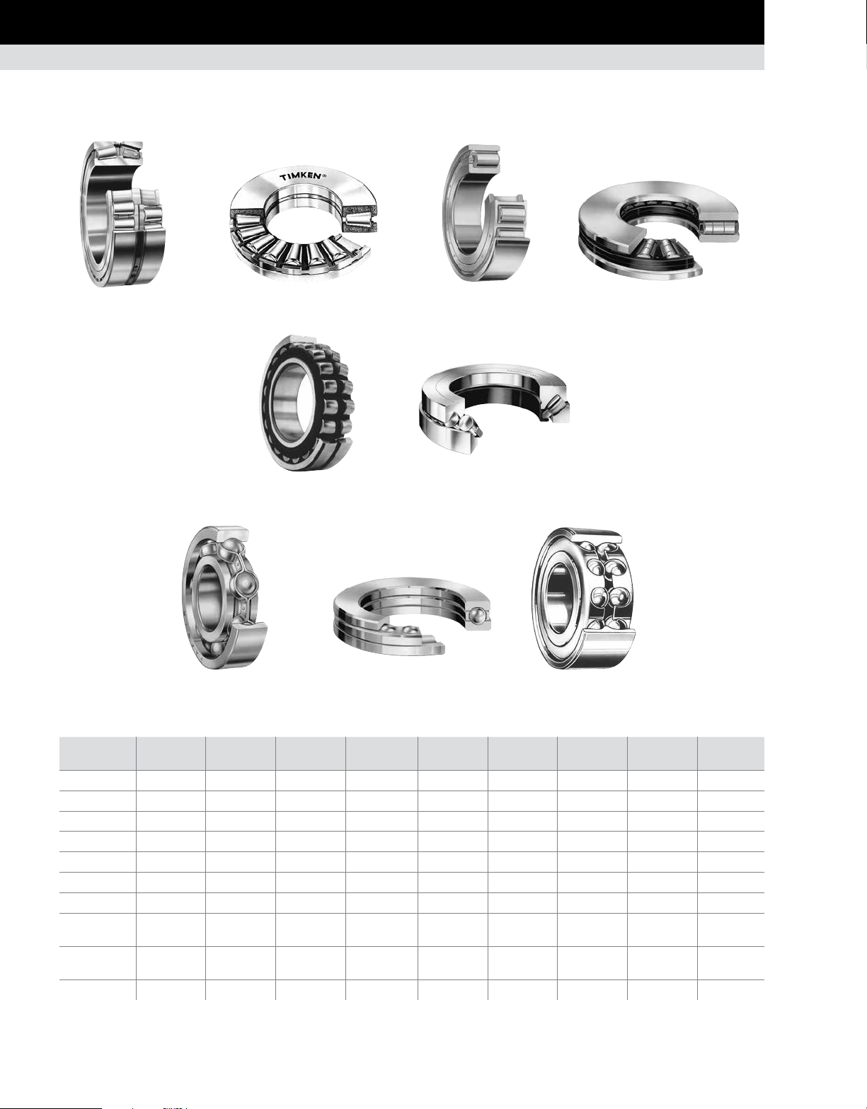
BEARING TYPES
BEARING TYPES
Cylindrical roller bearingTapered roller bearing Thrust tapered roller bearing Thrust cylindrical roller bearing
Spherical roller bearing
Thrust spherical roller bearing
Radial ball bearing Thrust ball bearing Angular contact ball bearing
TABLE 1. RELATIVE OPERATING CHARACTERISTICS OF VARIOUS BEARING TYPES
Characteristic
Pure radial load Good Unsuitable Excellent Unsuitable Good Unsuitable Good Poor Fair
Pure axial load Good Excellent Unsuitable Good Fair Excellent Fair Excellent Good
Combined load Excellent Poor Fair Unsuitable Good Fair Good Poor Excellent
Moment load Excellent Poor Unsuitable Unsuitable Unsuitable Unsuitable Fair Poor Good
High stiffness Excellent Excellent Good Excellent Good Good Fair Good Good
Low friction Good Good Excellent Poor Fair Fair Excellent Good Good
Misalignment Poor Poor Poor Unsuitable Excellent Excellent Good Poor Poor
Locating position
(fixed)
Non-locating
position (floating)
Speed Good Good Excellent Poor Fair Fair Excellent Excellent Excellent
Tapered Roller
Bearing
Excellent Good Fair Fair Good Good Good Excellent Good
Good Unsuitable Excellent Unsuitable Good Unsuitable Good Unsuitable Good
Thrust Tapered
Roller Bearing
Cylindrical Roller
Bearing
Thrust Cylindrical
Roller Bearing
Spherical Roller
Bearing
Thrust Spherical
Roller Bearing
Radial
Ball Bearing
Thrust Ball
Bearing
Angular Contact
Ball Bearing
10 TIMKEN ENGINEERING MANUAL
Page 13
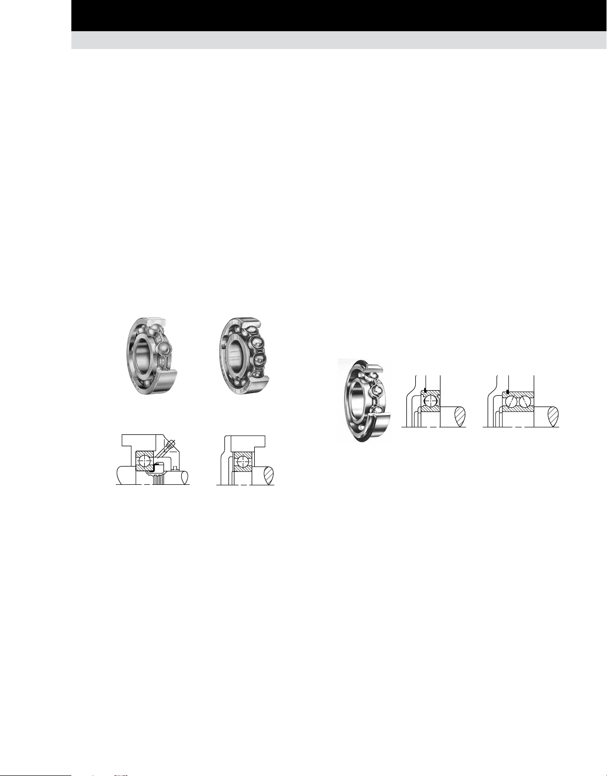
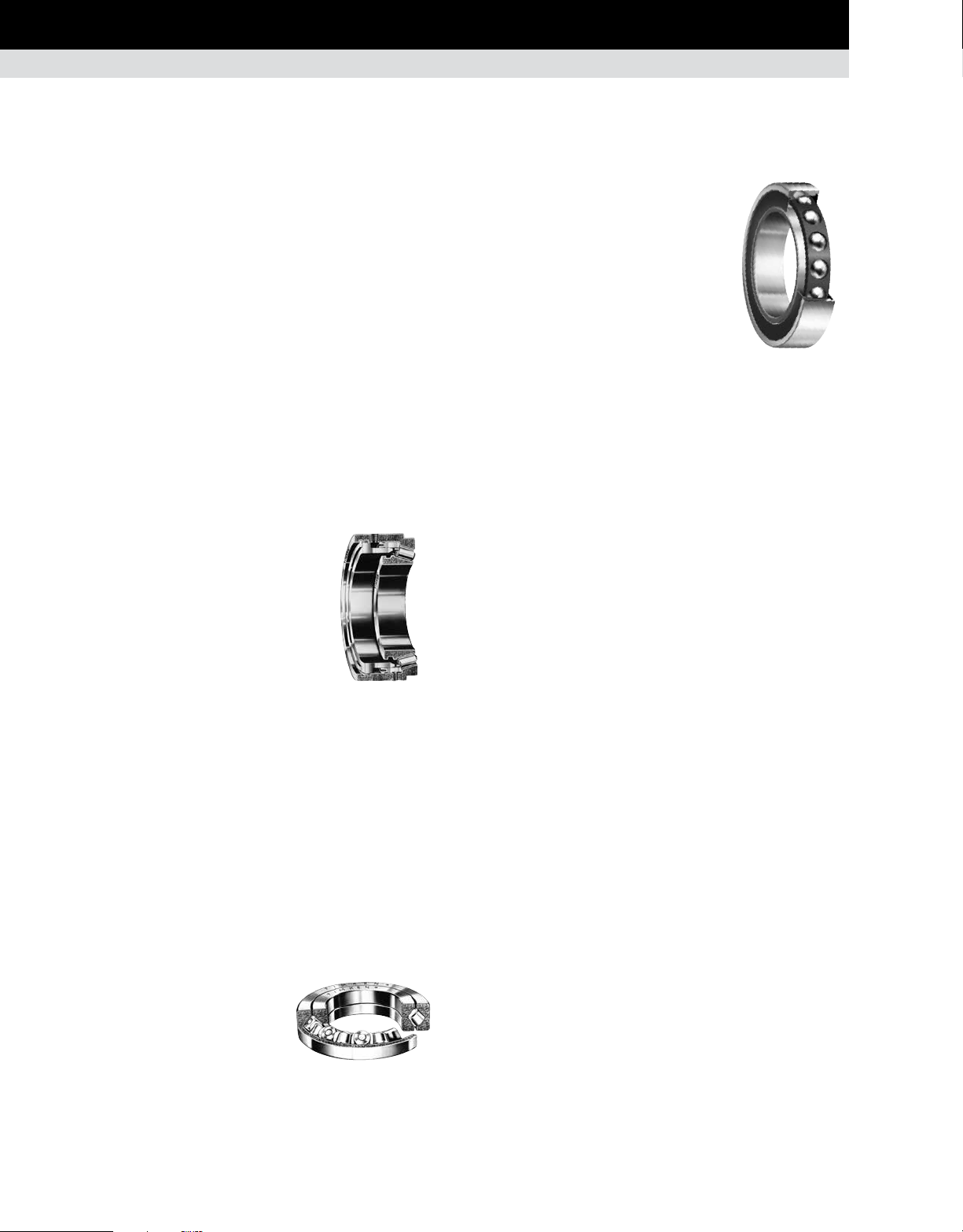
RADIAL BALL BEARINGS
Although radial ball bearings are designed primarily to support a
radial load, they perform relatively well under thrust or combined
radial and thrust load conditions.
Deep-groove ball bearings, commonly called Conrad or nonfilling-slot bearings, are assembled by displacing the inner
ring relative to the outer ring and inserting balls into the space
between the rings. By this method, only slightly more than half
the annular space between the inner and outer rings can be filled
with balls. Thus, capacity is limited.
To increase capacity, a filling slot or notch can be cut into the
inner ring, permitting the insertion of balls. Once the balls have
been inserted, the slot is filled by an insert. The increased number
of balls increases radial load capacity, but thrust load capacity
is sacrificed because of the filling slot.
The non-filling-slot or Conrad bearing is designated by the suffix
K and the filling slot bearing is designated by the suffix W.
BEARING SELECTION PROCESS
BEARING TYPES • RADIAL BALL BEARINGS
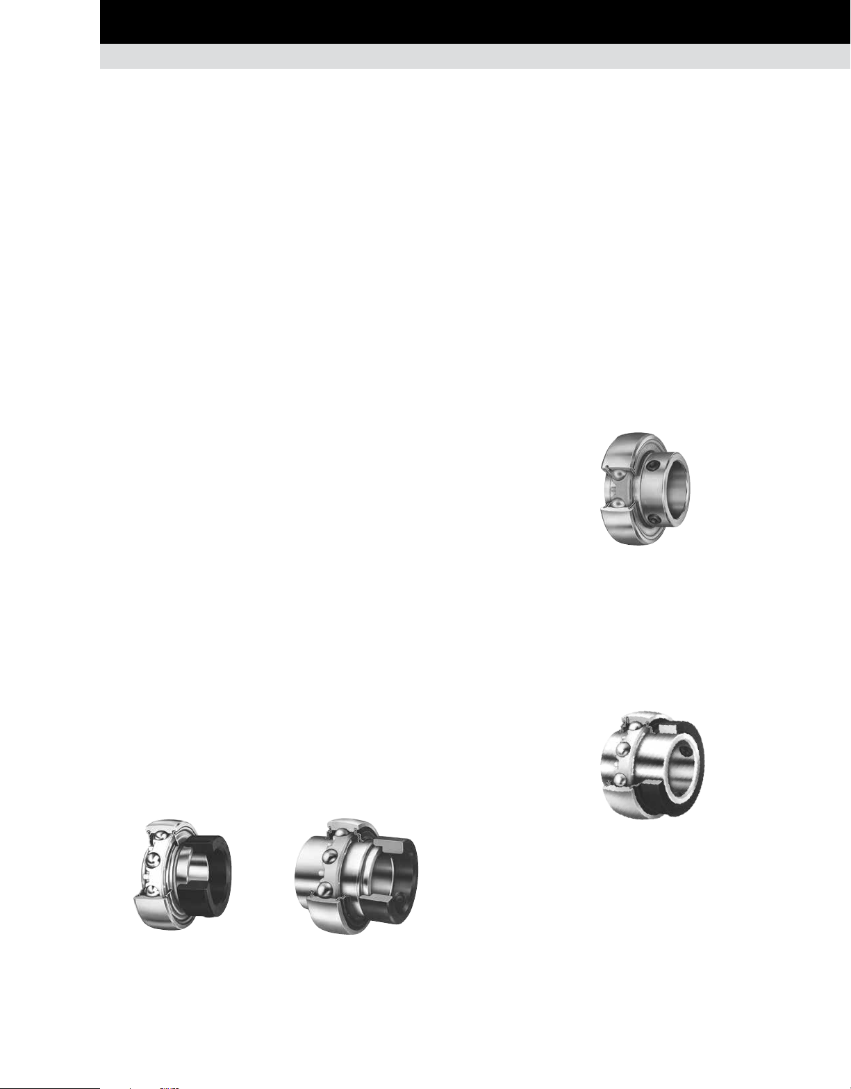
BALL BEARINGS WITH SNAP RINGS (WIRELOC)
Single-row radial ball bearings, including those with seals or
shields and open and shielded double-row types, are available
with snap rings. The snap ring protrudes from a groove in the
outer ring and acts as a shoulder to maintain bearing position. It
is designed for mounting in through-bored housings. This feature
is designated by adding the suffix G to the standard bearing
number. Single-shielded or sealed bearings with snap rings can
be supplied with the snap ring on the same side or opposite the
shield or seal position.
These bearings are advantageous in automobile transmission
design and in all applications where compactness is essential,
or where it is difficult and costly to machine housing shoulders.
The snap ring provides an adequate shoulder for the bearings
without a sacrifice in bearing capacity. The thrust capacity of the
snap ring in shear exceeds the thrust capacity of the bearing.
Typical designs illustrating how mounting simplification can be
accomplished through the use of snap ring bearings are shown
below.
Suffix K Suffix W
Conrad Filling Slot
Fixed mounting Floating mounting
Fig. 1. Typical mountings for radial ball bearings.
Fig. 2. Typical mountings for snap ring bearings.
TIMKEN ENGINEERING MANUAL
11
Page 14

BEARING SELECTION PROCESS
BEARING TYPES • ANGULAR CONTACT BALL BEARINGS
ANGULAR CONTACT BALL BEARINGS
SINGLE-ROW
Single-row, angular contact ball bearings are designed for
combination loading with high thrust capacity in one direction,
and are suggested for applications where the magnitude of the
thrust component is high enough to preclude the use of radialtype ball bearings. They are dimensionally interchangeable with
single-row radial bearings of corresponding sizes.
The angular contact ball bearing has a relatively large contact
angle, high ring depths, and a maximum complement of balls
assembled through a counterbore in the outer ring. These
features provide bearings with significantly more thrust capacity
than radial bearings of the same size.
Angular contact bearings are used in such applications as gear
reducers, pumps, worm drives, vertical shafts and machine tool
spindles, where they are frequently mounted in various singlerow arrangements.
DOUBLE-ROW
Double-row, angular contact ball bearings are used effectively
where heavy radial, thrust or combined loads demand axial
rigidity of the shaft. This type is similar to a duplex pair of singlerow bearings by virtue of its two rows of balls and angular-contact
construction, which provide greater axial and radial rigidity than
can be obtained by using a single-row radial bearing.
With the exception of small sizes, double-row ball bearings are
made in the filling slot construction, and therefore, do not have
as much thrust capacity as equivalent size single-row, angular
contact bearings mounted in duplex pairs. Fixed and floating
mountings of double-row bearings are shown. Smaller sizes are
supplied with polymer retainers.
Fixed mounting Floating mounting
Fig. 4. Typical mountings for double-row,
angular contact ball bearings.
Fig. 3. Typical mounting for single-row, angular
contact ball bearings.
12 TIMKEN ENGINEERING MANUAL
Page 15
BEARING SELECTION PROCESS
BEARING TYPES • PRECISION BEARINGS
PRECISION BEARINGS
(1)
MINIATURE AND THIN-SECTION
BALL BEARINGS
Timken produces precision ball bearings and assemblies
in miniature, instrument and thin-section series. All are
manufactured with quality steel, tolerances and features that
meet demanding application challenges. These precision
bearings and assemblies are found in surgical and diagnostic
imaging devices, precision pumps, measurement and material
handling equipment, as well as guidance, weapons and space
applications. Standard sizes range from 1 mm to 279.40 mm bore
(0.0250 in. to 11.000 in. bore).
Radial ball bearings
These Conrad bearings are available
in ISO P5/ABEC 5 to ISO P4/ABEC 7
precision levels as a standard catalog
offering. The deep-groove construction
allows for handling of radial, thrust or
combination loads. These are offered
primarily with 440C stainless-steel rings
and balls with one-piece fully machined
snap-in phenolic cages. In addition to
52100, other material and cage options
are available, as well as shields and
seals, and ceramic or titanium carbidecoated balls. Flanges are offered on miniature product. Typical
applications include guidance systems, medical (surgical
instruments and devices) and robotic joints.
Fig. 5. Radial ball
bearing.
Angular contact ball bearings
Angular contact ball bearings offer
maximum ball complement with a onepiece precision-machined retainer. The
increased ball complement, combined
with a relatively high contact angle,
maximizes axial stiffness. Angular
contact ball bearings are manufactured
to the same tolerances and standards
as the radial ball bearings. Rings and
balls are normally 440C stainless steel,
but other material options are offered.
Steel and ceramic balls are available
as standard. Typical applications use
preloaded pairs for maximum stiffness,
high speeds and precise positioning. These include surgical
handpieces, control moment gyros and other high-speed or highstiffness applications.
Fig. 6. Angular
contact ball bearing.
Fractured ring ball bearings
These bearings have outer rings
that are radially fractured in one
location. This permits the ring to be
opened for complete flexibility in the
choice of ball complement and cage
in a deep-groove radial bearing.
High-strength stainless-steel holding
bands are pressed on the ground
shoulders to retain tight abutment
and alignment of the fractured
surface during handling and normal
operation. Full complement and
retainer configurations are available.
Typical applications have a limited radial cross section and a
limited axial width. These applications require a bearing with
maximum radial capacity, as well as axial capacity in both
directions.
Fig. 7. Fractured ring
ball bearing.
Pivot ball bearings
Designed for space
constrained environments
where low torque is required,
pivot bearings use the mating
shaft for the inner raceway.
These bearings achieve
maximum power density with a
full complement of larger balls,
no cage or inner ring. Shields are available for the standard line.
Typical applications are in guidance systems, such as commercial
gyroscopes.
Fig. 8. Pivot ball bearing.
Thrust ball bearings
These bearings are designed for
applications where high axial
load, low speed and relatively high
torque are allowable. The standard
offering has all stainless steel
components for use where inert
materials are required. Stainless
steel allows operation as a fuel
control governor.
Fig. 9. Thrust ball bearing.
(1)
For additional information, refer to the Timken Super Precision Bearings for
Machine Tool Applications Catalog (order no. 5918) on www.timken.com.
TIMKEN ENGINEERING MANUAL
13
Page 16
BEARING SELECTION PROCESS
BEARING TYPES • PRECISION BEARINGS
PRECISION BEARINGS – continued
TAPERED ROLLER BEARINGS
Timken’s high-precision tapered roller bearings consist of
carefully matched components that offer an added degree of
fine-tuning in the bearing setting and adjustment procedure to
maximize customer machine productivity. Timken manufactures
high-speed designs with a variable preload capability for optimum
performance. Timken also manufacturers Precision Plus bearings –
having an overall radial runout less than a single micron.
TS and TSF single-row bearings
These bearings are similar in design to the types described on
page 16. They are only produced in high-precision quality, to be
used in machine tool spindles, printing press cylinders and other
applications where accuracy of rotation is required.
TSHR - Hydra-Rib™ bearing with
preload adjustment device
For many applications, notably in
the machine tool industry, bearings
are required to run at high speeds
with a controlled preload setting. The
Hydra-Rib™ bearing has a floating
outer ring rib controlled by hydraulic
or pneumatic pressure, which ensures
that the required bearing preload is
maintained irrespective of the differential
expansions or changes in loading taking
place within the system.
Fig. 10. Hydra-Rib™
bearing.
TXR - crossed roller bearing
A crossed roller bearing is two sets of bearing rings and rollers
brought together at right angles with alternate rollers facing
opposite directions. TXR bearings have a section height not
much greater than that of a TS bearing. The steep angle, tapered
geometry of the bearing causes the load-carrying center of each
of the rings to be projected along the axis, resulting in a total
effective bearing spread many times greater than the width of
the bearing itself. This type of bearing offers a high resistance to
overturning moments.
The normal design of the bearing
is type TXRDO, which has a double
outer ring and two inner rings,
with rollers spaced by polymer
cages. Crossed roller bearings are
manufactured in precision classes.
Fig. 11. TXR crossed roller
bearing.
TXR
SUPER PRECISION BALL BEARINGS
The Timken line of super precision
machine tool ball bearings is designed
to meet ISO and ABEC tolerance levels.
However, Timken manufactures all
super precision ball bearings to surpass
ISO/ABMA criteria to ensure that the
end users receive only the highest
quality product to maximize machine
performance. Spindle bearings are the
most popular type of super precision
ball bearing used within the machine
tool industry. These angular contact
bearings are used primarily in precision, high-speed machine
tool spindles. Timken manufactures super precision machine
tool bearings in four metric ISO dimensional series. In addition,
because of specialized variations of bearing design and geometry,
Timken offers a total of seven angular contact bearing types within
these four basic series:
ISO 19 (9300WI, 9300HX series).
•
ISO 10 (9100WI, 9100HX, 99100WN series).
•
ISO 02 (200WI series).
•
ISO 03 (300WI series).
•
Multiple internal geometries are available to optimize either loadcarrying capacity or speed capability with part number suffixes
designated as: WI, WN, HX or K. WI-type bearings are designed to
maximize capacity of the various bearing cross sections and are
used in low to moderate speeds. The HX is Timken’s proven highspeed design. It has a significant advantage at higher speeds,
generating less heat and less centrifugal loading forces. The
WN-type is generally a compromise between the WI and HX as
it offers higher speed capability than the WI, but lower capacity,
higher stiffness and lower speed capability than the HX design.
Most of the bearing types are available in either 15 degree
(2MM) or 25 degree (3MM) contact angles. In addition, Timken
now stocks more ceramic ball sizes than ever for the highest
speed requirements. The K-type deep-groove (Conrad) super
precision radial ball bearing is generally used in applications
where capacity and stiffness do not require sets containing
multiple bearings. By virtue of the single-row, radial deep-groove
construction, and super precision level tolerances, these are
capable of carrying thrust loads in either direction. Also, they
Fig. 12. Super precision
ball bearing.
14 TIMKEN ENGINEERING MANUAL
Page 17
BEARING SELECTION PROCESS
BEARING TYPES • PRECISION BEARINGS • BALL BEARINGS WITH LOCKING DEVICES
have a relatively high-speed capability – especially if a light axial
preload is applied. Timken offers deep-groove super precision ball
bearings in the following ISO dimensional series:
ISO 10 (9100K series).
•
ISO 02 (200K series).
•
ISO 03 (300K series).
•
For additional information, refer to the Timken Super Precision
Bearings for Machine Tool Applications Catalog (order number
5918) on www.timken.com. Or, contact your Timken engineer.
BALL BEARINGS WITH
LOCKING DEVICES
By virtue of their independent locking devices, these bearings
are suitable for mounting on straight shafting (no shoulders,
etc.). They are often supplied with spherical outer rings for selfalignment at mounting. Mounted alignment is usually required
because these bearings are generally assembled into pillow
blocks or flanged cartridges, or other housings bolted to pedestals
or frames independent of each other.
Easiest of all to install, wide inner ring ball bearings with selflocking collars are available in various sizes. These bearings,
shown with various seal and inner ring width variations, serve
many purposes in farm and industrial applications.
SETSCREW SERIES BEARINGS
The GYA-RRB and the GY-KRRB series are extended inner ring and
wide inner ring type bearings with specially designed setscrews
to lock on the shaft. These bearings can be purchased so that
they can be relubricated. Positive contact land-riding R-Seals
provide protection against harmful contaminants and retain
lubricant. Extended inner ring bearings are used when space is
at a premium and overturning loads are not a problem. The wide
inner ring setscrew series is available when additional surface
contact on the shaft is a requirement for added stability.
Fig. 14. YA-RR series.
SELF-LOCKING (ECCENTRIC) COLLAR
Timken invented the eccentric self-locking collar to facilitate
mounting of wide inner ring bearings. The self-locking collar
eliminates the need for locknuts, lock washers, shoulders, sleeves
and adapters.
The locking collar has a counterbored recess eccentric with
the collar bore. This eccentric recess engages or mates with an
eccentric cam end of the bearing inner ring when the bearing is
assembled on the shaft.
The collar is engaged on the inner ring cam of the bearing. This
assembly grips the shaft tightly with a positive binding action that
increases with use. No adjustments are necessary. The collar
setscrew provides supplementary locking.
RA-RR series Shroud-seal KRRB series
extended inner ring wide inner ring
with locking collar with locking collar
CONCENTRIC COLLAR
Using the concentric collar, the bearing is locked to the shaft by
two setscrews, 120 degrees apart, tightened in the collar and
passing through drilled holes in the inner ring. These units are
suited for applications where space is limited and reversing shaft
rotation is encountered.
Fig. 15. GC-KRRB series.
Fig. 13. Self-locking (eccentric) collar.
TIMKEN ENGINEERING MANUAL
15
Page 18
BEARING SELECTION PROCESS
BEARING TYPES • TAPERED ROLLER BEARINGS
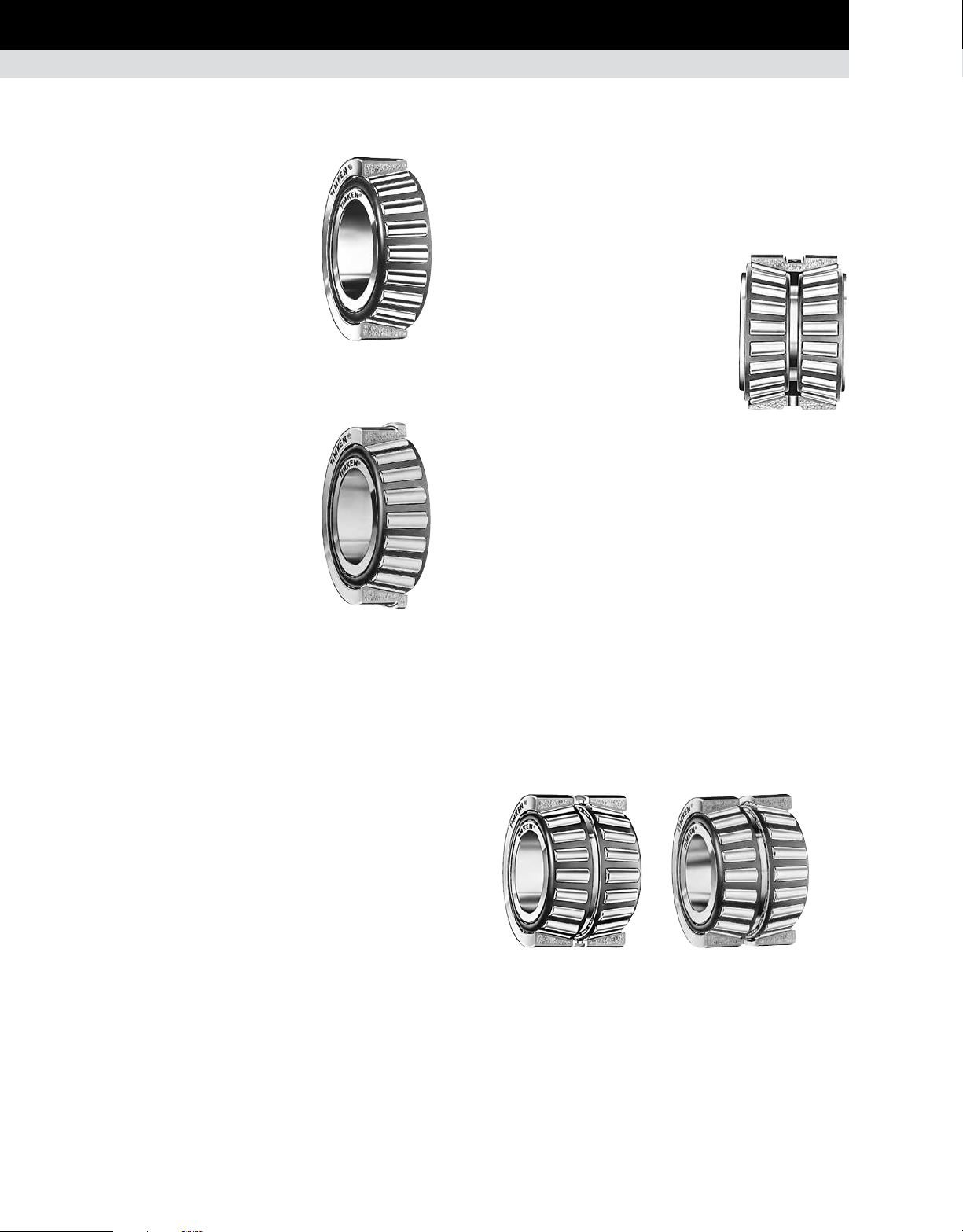
TAPERED ROLLER BEARINGS
SINGLE-ROW BEARINGS
TS - Single-row
This is the basic and the most widely
used type of tapered roller bearing. It
consists of the inner ring assembly and
the outer ring. It is usually fitted as one
of an opposing pair. During equipment
assembly, single-row bearings can
be “set” to the required clearance
(endplay) or preload condition to optimize
performance.
TSF - Single-row,
with flanged outer ring
The TSF type is a variation on the basic
single-row bearing. TSF bearings have
a flanged outer ring to facilitate axial
location and accurately aligned seats in
a through-bored housing.
Fig. 16. Single-row
TS bearing.
Fig. 17. Single-row
TSF bearing with
flanged outer ring.
DOUBLE-ROW BEARINGS
TDO - Double outer ring
This has a one-piece (double) outer ring
and two single inner-rings. It is usually
supplied complete with a inner-ring
spacer as a pre-set assembly. This
configuration gives a wide effective
bearing spread and is frequently chosen
for applications where overturning
moments are a significant load
component. TDO bearings can be used
in fixed (locating) positions or allowed to
float in the housing bore, for example, to
compensate for shaft expansion. TDOCD
outer rings also are available in most
sizes. These outer rings have holes in the
O.D. that permit the use of pins to prevent
outer ring rotation in the housing.
Fig. 18. Double-row
TDO bearing.
TDI - Double inner ring
TDIT - Double inner ring with tapered bore
Both comprise a one-piece (double) inner ring and two single
outer rings. They are usually supplied complete with an outerring spacer as a pre-set assembly. TDI and TDIT bearings can be
used at fixed (locating) positions on rotating shaft applications.
For rotating housing applications, the double inner ring of type
TDI can be used to float on the stationary shaft. Type TDIT has
a tapered bore to facilitate removal when an interference fit is
essential, yet regular removal is required.
16 TIMKEN ENGINEERING MANUAL
TDI
Fig. 19. Double-row, double-inner-ring bearings.
TDIT
Page 19
BEARING SELECTION PROCESS
BEARING TYPES • TAPERED ROLLER BEARINGS
TNA - Non-adjustable
TNASW - Non-adjustable with lubricant slots
TNASWE - Non-adjustable with lubricant
slots and extended back face rib
These three bearing types are similar to the TDO with a one-piece
(double) outer ring and two single inner rings. The inner ring
front faces are extended so they abut, eliminating the need for a
separate inner-ring spacer. Supplied with a built-in clearance to
give a standard setting range, these bearings provide a solution
for many fixed or floating bearing applications where optimum
simplicity of assembly is required.
Types TNASW and TNASWE are variations having chamfers
and slots on the front face of the inner ring to provide lubrication
through the shaft. Type TNASWE have extended back face ribs
on the inner rings which are ground on the O.D. to allow for the
use of a seal or stamped closure. These designs are typically
used on stationary shaft applications.
SPACER ASSEMBLIES
Any two single-row bearings (type TS) can be supplied as a
double-row, pre-set, ready-to-fit assembly by the addition of
spacers, machined to pre-determined dimensions and tolerances.
Spacer assemblies are provided in two types: "2S" and "SR". This
concept can be applied to produce custom-made double-row
bearings to suit specific applications. In addition to providing
a bearing that automatically gives a pre-determined setting at
assembly without the need for a manual setting, it is possible
to modify the assembly width to suit an application, simply by
varying the spacer widths.
2S
Fig. 21. Spacer assemblies.
SR
TNA TNASW TNASWE
Fig. 20. Double-row, non-adjustable bearings.
2S - Two single-row assembly
Often referred to as snap-ring assemblies, type 2S consist of
two basic single-row bearings (type TS). They are supplied
complete with inner-ring and outer-ring spacers to give a predetermined bearing setting when assembled. Type 2S have a
specified setting range to suit the duty of the application. They
have an inner-ring spacer and a snap-ring, which also serves as
the outer-ring spacer, to give axial location in a through-bored
housing.
SR - SET-RIGHT™ assembly
Type SR are made to a standard setting range, based on Timken’s
SET-RIGHT™ automated setting technique suitable for most
industrial applications. They have two spacers and an optional
snap-ring that may be used for axial location. Because both types
are made up of popular sizes of single-row bearings, they provide
a low-cost option for many applications.
TIMKEN ENGINEERING MANUAL
17
Page 20
BEARING SELECTION PROCESS
BEARING TYPES • TAPERED ROLLER BEARINGS
TAPERED ROLLER BEARINGS – continued
There are three basic mounting arrangements for spacer
assemblies.
Type 2TS-IM (indirect mounting)
•
These consist of two single-row bearings with an inner-ring
and outer-ring spacer. In some applications, the outer-ring
spacer is replaced by a shoulder in the bearing housing.
Type 2TS-DM (direct mounting)
•
These consist of two single-row bearings, with inner rings
abutting and an outer-ring spacer. They are generally used
at fixed (locating) positions on rotating shaft applications.
Type 2TS-TM (tandem mounting)
•
Where combined radial and thrust load capacity is
required, but the thrust component is beyond the capacity
of a single bearing (within a given maximum O.D.), two
single-row bearings can be mounted in tandem.
Appropriate inner-ring and outer-ring spacers are supplied.
Consult your Timken engineer for the most effective
and economical solution.
2TS-IM
2TS-DM
Fig. 22. Basic spacer assemblies.
2TS-™
18 TIMKEN ENGINEERING MANUAL
Page 21
PACKAGED BEARINGS
BEARING SELECTION PROCESS
BEARING TYPES • TAPERED ROLLER BEARINGS
PINION PAC
Fig. 23. Packaged bearings.
Pinion Pac
™
™
bearing
UNIPAC
™
UNIPAC-PLUS
™
The Pinion Pac™ bearing is a ready-to-install, pre-set and sealed
package consisting of two rows of tapered roller bearings
mounted in a carrier. It is custom designed for the final drive
pinions of heavy commercial vehicles. The package gives the
differential pinion builder considerable improvements in reliability,
ease of assembly and supply logistics.
™
UNIPAC
bearing
The UNIPAC-PLUS™ bearing is a ready-to-install, pre-set,
pre-lubricated and sealed double-row assembly with a flanged
outer ring. Originally designed for the high-volume needs of
passenger car wheels, the UNIPAC bearing now has wider
application in wheel hubs of heavy vehicles as well as in industrial
equipment.
The UNIPAC bearing provides improvements in reliability, ease
of assembly and supply logistics.
AP
™
bearing
AP
™
SP
™
The AP™ bearing is a self-contained assembly, made in a wide
range of sizes. It consists of two single inner rings, a counterbored
double outer ring, a backing ring, two radial seals, an end cap
and cap screws. The AP bearing is supplied as a pre-set, prelubricated and sealed package. It was originally designed for
railroad journals, but also is used in many industrial applications.
™
SP
bearing
Similar in concept to AP bearings, the SP™ bearing is designed
for rail journal bearing applications. The SP bearing type differs
from the AP bearing in that SP bearings are more compact in size
and are manufactured to metric boundary dimensions.
™
UNIPAC-PLUS
bearing
The UNIPAC-PLUS™ bearing is a ready-to-install, pre-set,
sealed double-row assembly with a flanged outer ring. It also is
lubricated for the reasonable life of the bearing. It is designed
for wheel applications subjected to moderate to heavy loading.
The UNIPAC-PLUS bearing provides advantages of improved
reliability, reduced weight and easier assembly.
TIMKEN ENGINEERING MANUAL
19
Page 22
BEARING SELECTION PROCESS
BEARING TYPES • TAPERED ROLLER BEARINGS
HIGH-SPEED BEARINGS
TSMA - Single-row with axial oil
TSMR - Single-row with radial oil
Some applications require extreme high-speed capability where
special lubrication methods must be provided.
The TSMA and TSMR are single-row
bearings with provisions for lubrication of
critical roller-rib contact area to ensure
adequate lubrication at high speeds.
The TSMA concept works by capturing
oil in a manifold (attached to the inner
ring), which is then directed to the
rib-roller contact through holes drilled
axially through the large inner ring rib.
The TSMR functions in a similar manner
with the difference being that holes are
drilled radially from the inner ring bore
to the large rib face. Oil is captured in
a circumferential groove in the inner
ring bore. It is directed to the rib-roller
contact area through radial holes.
Fig. 24. TSMA bearing.
OTHER DOUBLE-ROW BEARINGS
Type TDIE - Extended double inner ring
Type TDIA - Extended single inner ring
These double-row bearings are designed for applications where
it is required to lock the loose-fitted inner ring to a shaft, with
provision also for effective closure or sealing. Typical applications
include pillow blocks, disc-harrow and similar agricultural
machinery shafts and line shafts.
Type TDIE is available in two forms – cylindrical bore with the
inner ring extended at both ends and provisions for setscrews
and locking collars at each end, or with an inherently self-locking
square bore – ideal for farm machinery applications.
Type TDIA is similar to type TDIE with a cylindrical bore. There
is a provision for a locking collar at one end only. The compact
configuration is suited to pillow blocks and similar applications.
On all types, the hardened and ground O.D. of the inner ring
extension provides an excellent surface for effective closure
or sealing.
Type TNASWH - Non-adjustable, heavy-duty,
double outer ring
Type TNASWHF - Non-adjustable, heavy-duty,
with flanged double outer ring
These are double-row bearing assemblies with two inner rings
and a one-piece outer ring, similar to type TNASWE listed in this
manual on page 17.
The outer rings have a heavy wall section (type TNASWH),
allowing the bearings to be used directly as steady rest rollers,
in sheet and strip levellers or, with a flange (type TNASWHF), as
a complete wheel assembly for use on rails.
The outer ring is extended at both ends and counterbored to
accept stamped closures. Contacting seals are available for
certain sizes. These bearings are typically supplied as a unit
assembly and are pre-lubricated.
TDIE TDIE (square bore)
Fig. 25. Other double-row bearings.
20 TIMKEN ENGINEERING MANUAL
TDIA
TNASWH
TNASWHF
Page 23
BEARING SELECTION PROCESS
BEARING TYPES • TAPERED ROLLER BEARINGS
FOUR-ROW BEARINGS
Four-row bearings combine the inherent high-load, radial/thrust
capacity and direct/indirect mounting variations of tapered roller
bearings into assemblies of maximum load rating in a minimum
space. Their main application is on the roll necks of rolling mill
equipment.
All four-row bearings are supplied as pre-set matched assemblies,
with all components numbered to ensure correct installation
sequence.
Type TQO - Quad taper
Type TQOW - Quad taper with lubrication slots
These pairs of directly mounted bearings consist of two double
inner rings, two single and one double outer ring, with an innerring spacer and two outer-ring spacers. These types are used
on roll necks of low- and medium-speed rolling mills, applied to
the necks with a loose fit. When the fillet and/or filler rings do
not have lubrication slots, they are provided in the faces of the
bearing inner rings (type TQOW). Slots in the inner-ring spacer
permit lubricant to flow from the bearing chamber to the roll neck.
The inner-ring spacers also are hardened to minimize face wear.
Type TQITS
Type TQITSE
The main feature of these bearings is a tapered bore – the taper
being matched and continuous through the inner rings. This
permits an interference fit on the backup rolls of high-speed mills,
where a loose inner ring fit of a straight bore type TQO bearing
could result in excessive neck wear.
These four-row bearings consist of two pairs of indirectly
mounted bearings: two single and one double inner ring, four
single outer rings and three outer-ring spacers. The adjacent
faces of the inner-rings are extended so that they abut,
eliminating the need for inner-ring spacers. The indirect mounting
of the bearing pairs increase the overall effective spread of the
bearing, to give optimum stability and roll rigidity.
Type TQITSE is the same as TQITS, but has an extension to the
large bore inner ring adjacent to the roll body. This not only
provides a hardened, concentric and smooth surface for radial
lip seals, but also improves roll neck rigidity by eliminating a fillet
ring. This allows the centerline of the bearing to move closer to
the roll body. It also permits shorter and less costly rolls.
Fig. 26. Four-row
bearing assemblies.
TQO/ TQOW
Sealed roll neck
The sealed roll neck bearing is similar to the TQO. A specially
designed sealing arrangement is incorporated in the bearing
to endure highly contaminated environments. The special seal
design is built into the bearing to prevent ingress of contamination
from outside the bearing envelope and extend the useful
bearing life.
Fig. 27. Sealed roll neck
bearing.
TQITS TQITSE
Fig. 28. Four-row bearings with tapered bore.
SEALED BEARINGS
TSL
Timken offers a wide range of sealed
bearings such as the DUO-FACE
shown in fig 29. The TSL incorporates a DUOFACE PLUS seal, making it an economical
choice for grease-lubricated applications
at moderate speeds. See the SEALS section
in the back of this manual for additional seal
designs.
®
PLUS seal
Fig. 29. TSL sealed
bearing.
TIMKEN ENGINEERING MANUAL
21
Page 24

BEARING SELECTION PROCESS
BEARING TYPES • THRUST BEARINGS
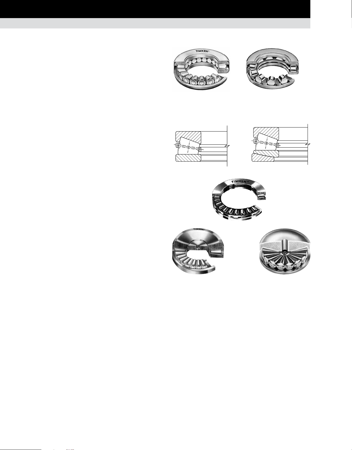
THRUST BEARINGS
Standard types of thrust bearings manufactured by Timken are
included in this section. Each type is designed to take thrust
loads, but four types (TVL, DTVL, TTHD and TSR) accommodate
radial loads as well. All types reflect advanced design concepts,
with large rolling elements for maximum capacity. In roller thrust
bearings, controlled-contour rollers are used to ensure uniform,
full-length contact between rollers and raceways with resultant
high capacity. Thrust bearings should operate under continuous
load for satisfactory performance.
Type TVB – Grooved-ring thrust ball bearing
Type TVL – Angular contact thrust ball bearing
Type DTVL – Two direction angular contact thrust ball bearing
Type TP – Thrust cylindrical roller bearing
Type TPS – Self-aligning thrust cylindrical roller bearing
Type TTHD – Thrust tapered roller bearing
Type TSR – Thrust spherical roller bearing
Type TTHDFL – V-flat thrust tapered roller bearing
Type TTVS – Self-aligning V-flat thrust tapered roller bearing
Type TTSP – Steering pivot thrust cylindrical roller bearing
ring is shaft-mounted. The stationary ring should be housed with
sufficient O.D. clearance to allow the bearing to assume its proper
operating position. In most sizes, both rings have the same bore
and O.D. The housing must be designed to clear the O.D. of the
rotating ring, and it is necessary to step the shaft to clear the
bore of the stationary ring.
Type TVL is a separable angular contact ball bearing primarily
designed for unidirectional thrust loads. The angular contact
design, however, will accommodate combined radial and thrust
loads since the loads are transmitted angularly through the balls.
The bearing has two hardened and ground steel rings with
ball grooves and a one-piece brass cage that spaces the ball
complement. Although not strictly an angular ball bearing, the
larger ring is still called the outer ring, and the smaller the inner
ring. Timken standard tolerances for type TVL bearings are
equivalent to ABEC 1 where applicable, but higher grades of
precision are available.
Usually the inner ring is the rotating member and is shaft mounted.
The outer ring is normally stationary and should be mounted with
O.D. clearance to allow the bearing to assume its proper operating
position. If combined loads exist, the outer ring must be radially
located in the housing.
THRUST BALL BEARINGS
Thrust ball bearings are used for lighter loads and higher speeds
than thrust roller bearings. Types TVB, TVL and DTVL are shown
in fig. 30.
Type TVB thrust ball bearing is separable and consists of two
hardened and ground steel rings with grooved raceways, and
a cage that separates and retains precision-ground and lapped
balls. The standard cage material is brass, but this may be varied
according to the requirements of the application. Timken
tolerances for type TVB bearings are equivalent to ABEC 1 where
applicable, but higher grades of precision are available.
Type TVB bearings provide axial rigidity in one direction and their
use to support radial loads is not suggested. Usually the rotating
Fig. 30. Thrust ball bearing types.
standard
Type TVL bearings should always be operated under thrust load.
Normally, this presents no problem as the bearing is usually
applied on vertical shafts in oil field rotary tables and machine
tool indexing tables. If constant thrust load is not present, it should
be imposed by springs or other built-in devices.
Low friction, cool running and quiet operation are advantages of
TVL bearings, which may be operated at relatively high speeds.
TVL bearings also are less sensitive to misalignment than other
types of rigid thrust bearings.
DTVL is similar in design to TVL except the DTVL has an additional
ring and ball complement permitting it to carry moderate thrust
in one direction and light thrust in the other direction.
DTVLTVLTVB
22 TIMKEN ENGINEERING MANUAL
Page 25
BEARING SELECTION PROCESS
BEARING TYPES • THRUST BEARINGS
THRUST CYLINDRICAL ROLLER BEARINGS
Thrust cylindrical roller bearings withstand heavy loads at
relatively moderate speeds. Standard thrust bearings can be
operated at bearing O.D. peripheral speeds of 3000 fpm (15 m/s).
Special design features can be incorporated into the bearing and
mounting to attain higher operating speeds.
Because loads are usually high, extreme-pressure (EP) lubricants
should be used with cylindrical roller thrust bearings. Preferably,
the lubricant should be introduced at the bearing bore and
distributed by centrifugal force.
All types of thrust roller bearings are made to Timken Standard
Tolerances. Higher precision may be obtained when required.
Type TP thrust cylindrical roller bearings have two hardened
and ground steel rings, with a cage retaining one or more
controlled-contour rollers in each pocket. When two or more
rollers are used in a pocket, they are of different lengths and are
placed in staggered position in adjacent cage pockets to create
overlapping roller paths. This prevents wearing grooves in the
raceways and helps prolong bearing life.
Because of the simplicity of their design, type TP bearings are
economical. Shaft and housing seats must be square to the axis
of rotation to prevent initial misalignment problems.
THRUST SPHERICAL ROLLER BEARINGS
Type TSR
The TSR thrust spherical roller bearing design achieves a high
thrust capacity with low friction and continuous roller alignment.
The bearings can accommodate pure thrust loads as well as
combined radial and thrust loads. Typical applications are air
regenerators, centrifugal pumps and deep well pumps. Maximum
axial misalignment between inner and outer ring is ±2.5 degrees.
Fig. 32. Thrust spherical roller bearing, type TSR.
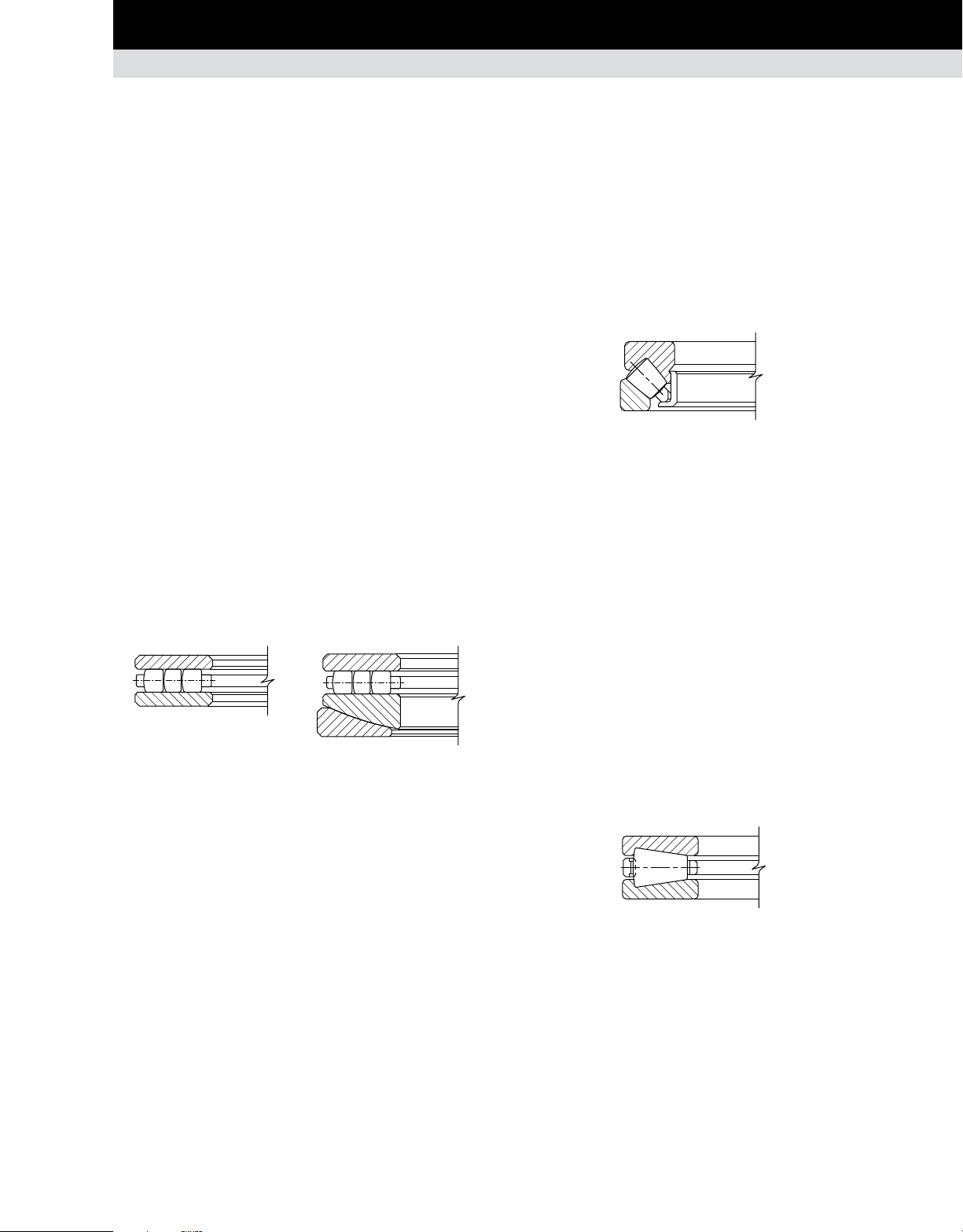
THRUST TAPERED ROLLER BEARINGS
Type TTHD
Type TTHD thrust tapered roller bearings have an identical pair
of hardened and ground steel rings with conical raceways and a
complement of controlled-contour tapered rollers equally spaced
by a cage. The raceways of both rings and the tapered rollers
have a common vertex at the bearing center. This assures true
rolling motion.
TP
TPS
Fig. 31. Thrust cylindrical roller bearings.
Type TPS bearings are the same as type TP bearings except one
ring is spherically ground to seat against an aligning ring, thus
making the bearing adaptable to initial misalignment. Its use
is not suggested for operating conditions where alignment is
continuously changing (dynamic misalignment).
TTHD bearings are well-suited for applications such as crane
hooks, where extremely high thrust loads and heavy shock must
be resisted and some measure of radial location obtained.
For very low-speed, heavily loaded applications, these bearings
are supplied with a full complement of rollers for maximum
capacity. For application review of the full complement type TTHD
bearing, consult your Timken engineer.
Fig. 33. Thrust tapered roller bearing, type TTHD.
TIMKEN ENGINEERING MANUAL
23
Page 26
BEARING SELECTION PROCESS
BEARING TYPES • THRUST BEARINGS
THRUST BEARINGS – continued
TTC cageless
TTSP steering pivot
There are two basic types of Timken® tapered roller thrust
bearings designed for applications where the only load
component is thrust, TTC and TTSP. The TTC bearing uses a full
complement of tapered rollers without a cage and is used when
the speeds are slow. The TTSP bearing uses a cage and is wellsuited for the oscillating motion of steering pivot positions.
Type TTHDFL Type TTVS
Type TTHDSX Type TTHDSV
V-flat tapered roller bearings (TTHDFL and TTVS) combine the
best features of thrust tapered and cylindrical roller bearings,
offering the highest possible capacity of any thrust bearing of its
size. V-flat design includes one flat ring and the second with a
tapered raceway matching the rollers. The design was originally
developed to be screwed down in metal rolling mill applications
where the thrust loads commonly exceed one million pounds.
These bearings have exceptional dynamic capacity within a given
envelope and provide superior static capacity. They are used
inheavily loaded extruders, cone crushers and other applications
where a wide range of operating conditions are found.
TTSPTTC
TTVSTTHDFL
TTHDFL
Most sizes utilize cages with hardened pins through the center
of the rollers, allowing closer spacing of the rollers to maximize
capacity. Smaller sizes have cast-brass cages, carefully
machined to permit full flow of lubricant.
Self-aligning V-flat bearings (TTVS) employ the same basic roller
and raceway design, except the lower ring is in two pieces, with
the contacting faces spherically ground permitting self-alignment
under conditions of initial misalignment. TTVS bearings should
not be used if dynamic misalignment (changing under load) is
expected.
TTHDSV
Fig. 34. Thrust tapered roller bearings.
TTHDSX
24 TIMKEN ENGINEERING MANUAL
Page 27
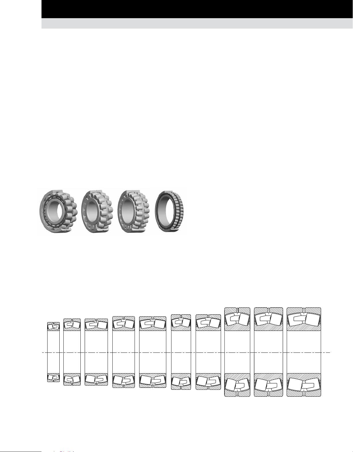
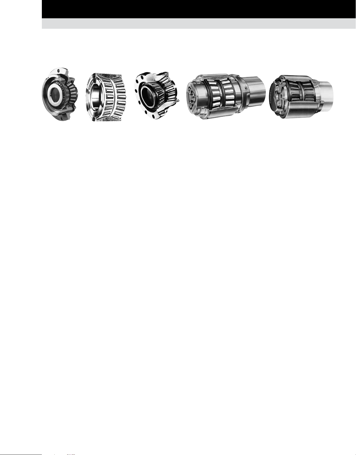
RADIAL SPHERICAL ROLLER BEARINGS
BEARING SELECTION PROCESS
BEARING TYPES • RADIAL SPHERICAL ROLLER BEARINGS
The principle styles of radial spherical roller bearings that Timken
offers are:
≤400 mm outer diameter: EJ, EM and EMB.
•
>400 mm outer diameter: YM, YMB, YMD and YP.
•
The newly redesigned Timken
higher load ratings, increased thermal speed ratings and reduced
operating temperatures compared to the previous offering.
In addition to these improvements, cage designs vary between
the different styles as noted below. See the cage section for
more details.
Style Cage Design
EJ Land-riding steel cage; one per row
EM / YM Roller-riding one-piece brass cage
EMB/YMB Land-riding one-piece brass cage
YMD Land-riding two-piece brass cage
YP Steel pin-type cage
EM/YM and
EMB/YMB
Fig. 35. Radial spherical roller bearings.
Most Timken spherical roller bearings are available with a
cylindrical bore as well as a tapered bore. Tapered bore bearing
part numbers are designated with a K suffix.
®
EJ, EM and EMB bearings offer
YMDEJ
YP
OPTIONAL FEATURES AVAILABLE WITH
TIMKEN SPHERICAL ROLLER BEARINGS
W33 lubrication groove and oil holes
A lubrication groove and three oil holes are provided in the
bearing outer ring as standard. This is designated by the W33
suffix. It eliminates the expense of machining a channel in the
housing bore for introducing lubricant to the bearing. This design
feature allows the lubricant to flow between the roller paths,
through a single lubrication fitting. The lubricant moves laterally
outward from the center of the bearing, reaching all contact
surfaces and flushing the bearing. To order, add the suffix W33
to the bearing number (e.g. 22216EMW33).
Bearings for vibratory applications
Timken offers specific spherical roller bearing designs for
vibratory applications. They are designated by the W800
modification code and made to a C4 clearance. Specify W800
when ordering. This design provides:
A lubrication groove on the outer ring with three lubrication
•
holes to facilitate bearing lubrication.
Extra-close running accuracy (P5) with high and low points
•
marked on the bearing.
Reduced bore and outside diameter tolerances.
•
Radial internal clearance is made in upper two-thirds of
•
C4 clearance range.
These bearings are available with either a cylindrical or tapered
bore.
A taper of 1:12 is standard except for 240, 241 and 242 series,
which have a taper of 1:30.
SERIES
239 230 240 231 241 222 232 213 223 233
Fig. 36. Radial spherical roller bearing series.
TIMKEN ENGINEERING MANUAL
25
Page 28
BEARING SELECTION PROCESS
BEARING TYPES • RADIAL CYLINDRICAL ROLLER BEARINGS
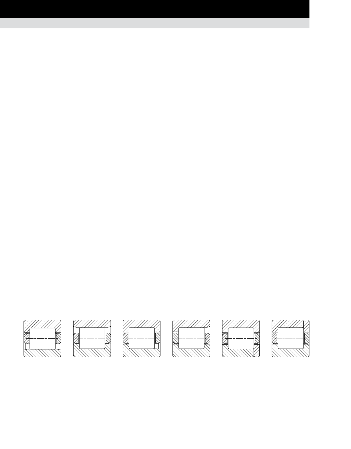
RADIAL CYLINDRICAL ROLLER BEARINGS
STANDARD STYLES
Timken® cylindrical roller bearings consist of an inner and outer
ring, a roller-retaining cage, and a complement of controlledcontour cylindrical rollers. Depending on the type of bearing,
either the inner or the outer ring has two roller-guiding ribs. The
other ring is separable from the assembly and has one rib or
none. The ring with two ribs axially locates the position of the
roller assembly. The ground diameters of these ribs may be used
to support the roller cage. One of the ribs may be used to carry
light thrust loads when an opposing rib is provided.
The decision as to which ring should be double ribbed is normally
determined by considering assembly and mounting procedures
in the application.
Type NU has double-ribbed outer and straight inner rings. Type
N has double-ribbed inner and straight outer rings. The use of
either type at one position on a shaft is ideal for accommodating
shaft expansion or contraction. The relative axial displacement
of one ring to the other occurs with minimum friction while the
bearing is rotating. These bearings may be used in two positions
for shaft support if other means of axial location are provided.
Type NJ has double-ribbed outer and single-ribbed inner
rings. Type NF has double-ribbed inner and single-ribbed outer
rings. Both types can support heavy radial loads, as well as
light unidirectional thrust loads. The thrust load is transmitted
between the diagonally opposed rib faces in a sliding action.
When limiting thrust conditions are approached, lubrication can
become critical. Your Timken engineer should be consulted for
assistance in such applications. When thrust loads are very light,
these bearings may be used in an opposed mounting to locate
the shaft. In such cases, shaft endplay should be adjusted at
time of assembly.
Type NUP has double-ribbed outer and single-ribbed inner ring
with a loose rib that allows the bearing to provide axial location
in both directions. Type NP has a double-ribbed inner ring and
a single-ribbed outer ring with a loose rib. Both types can carry
heavy radial loads and light thrust loads in both directions. Factors
governing the thrust capacity are the same as for types NJ and
NF bearings.
A type NUP or NP bearing may be used in conjunction with type
N or NU bearings for applications where axial shaft expansion is
anticipated. In such cases, the N or NU bearing accommodates
the shaft expansion. The NUP or NP bearing is considered the
fixed bearing because the ribs restrict the axial movement of
the rolling element. The fixed bearing is usually placed nearest
the drive end of the shaft to minimize alignment variations in the
drive. Shaft endplay, or float, is determined by the axial clearance
in the fixed bearing.
Types NU, N, NJ, NF, NUP and NP conform to ISO and DIN
standards for loose rib rings (thrust collars) and typical industry
diameters over or under roller.
The cylindrical roller bearing part numbers are in accordance
with ISO 15. They are composed of four digits, the first two digits
identify the dimensional series and the last two digits of the part
number are the bore size divided by 5. In the dimensional series,
the first digit is the width series and the second is the diameter
(outer) series. The width series increase width in the sequence
8 0 1 2 3 4 5 6 7. The diameter series increase radial section in
the sequence 7 8 9 0 1 2 3 4.
Types having an R prefix are similar in construction to their N
counterparts. However, they were designed to conform to ABMA
standards.
Inch-size bearings are identified by the letter I in the part number.
RIU, for example, indicates an inch bearing while RU indicates
the equivalent style in metric dimensions.
NU, RIU, RU N, RIN, RN NJ, RIJ, RJ NF, RIF, RF NUP, RIT, RT NP, RIP, RP
Fig. 37. Radial cylindrical roller bearings.
26 TIMKEN ENGINEERING MANUAL
Page 29

BEARING SELECTION PROCESS
BEARING TYPES • RADIAL CYLINDRICAL ROLLER BEARINGS
EMA SERIES
The Timken® single-row EMA series cylindrical roller bearings
incorporate a unique cage design, proprietary internal geometry
and special surface textures. These features help to improve
bearing performance and can help to improve uptime and reduce
maintenance costs.
The cage is a one-piece brass design with full-milled pockets.
It is a land-riding cage which, unlike traditional roller-riding
cages, minimizes drag on the roller elements. This reduces heat
generation and improves bearing life. The high cage rigidity
allows for more rollers than possible with other brass cage
configurations.
Proprietary profiles on the rings and/or rollers increase the ability
to handle heavier loads than competing designs.
Engineered processes for rings and rollers provide enhanced
surface textures, resulting in lower friction, lower operating
temperatures and longer bearing life.
EMA series bearings are available in types N, NU, NJ and NUP.
FULL-COMPLEMENT (NCF)
The full-complement (NCF) single-row bearings include integral
flanges on the inner and outer rings. These bearings also can
manage axial loads in one direction and permit small axial
displacements.
5200 METRIC SERIES
This series features enhanced radial load ratings due to its
internal design proportions. In this series, the outer ring is
double-ribbed and the inner ring is full-width with a cylindrical
O.D. The bearing also can be furnished without an inner ring
for applications where radial space is limited. When so used,
the shaft journal must be hardened to HRC 58 minimum, and the
surface finished to 15 RMS maximum. The W designation in the
suffix indicates the outer ring is provided. The inner ring also can
be furnished separately. The A prefix indicates that the inner ring
is furnished either separately or as part of the assembly.
The bearing is usually provided with a rugged stamped-steel cage
(S designation) and is land-riding on the outer ring ribs. The cage
features depressed bars, which not only space rollers evenly, but
retain them as a complete assembly with the outer ring. Cages
of machined brass (M designation) are available for applications
where reversing loads or high speeds might indicate their need.
Outer rings are made from bearing quality alloy steel. The inner
rings are deep-case hardened to accommodate the hoop stresses
resulting from heavy press fits.
The standard bearing is produced with radial internal clearances
designated as R6. Other internal clearances can be supplied upon
request. Proper roller guidance is assured by integral ribs and
roller end clearance control.
A-52xx-WS A-52xx-WM
52xx-WS A-52xx
Fig. 38. 5200 metric series bearings.
TIMKEN ENGINEERING MANUAL
27
Page 30
BEARING SELECTION PROCESS
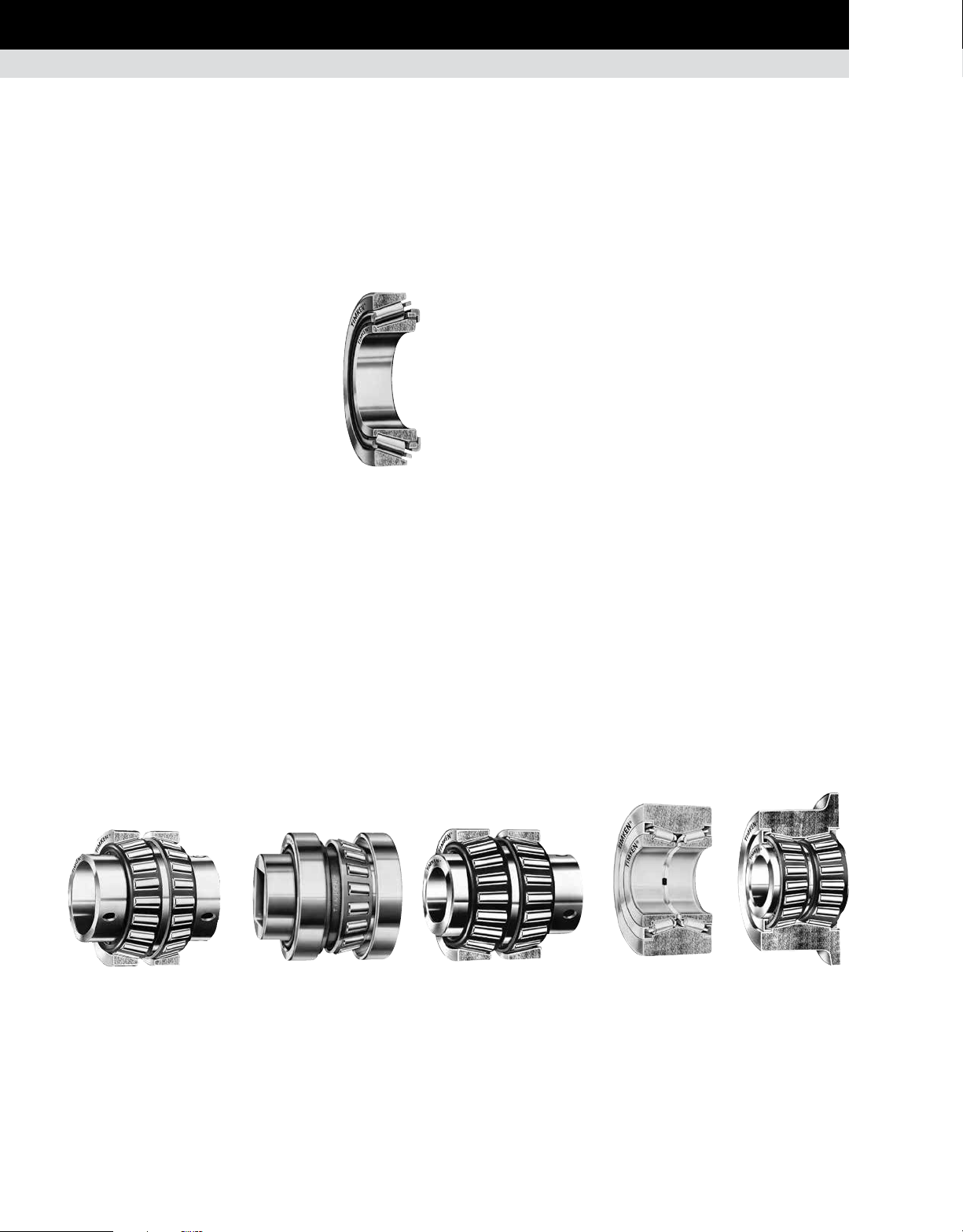
CAGES • TAPERED ROLLER BEARING CAGES
CAGES
Cages (also referred to as rolling element retainers) serve several
purposes in the proper operation of a rolling element bearing.
Cages separate the rolling elements and prevent rolling element
on rolling element contact and wear. Cages align the rolling
elements on the inner ring to prevent rolling element sliding,
skidding, and skewing to facilitate true rolling motion. For handling
purposes, cages retain the rolling elements on the inner ring
assembly to allow for bearing installation. In some instances,
cages also improve flow of the lubricant to the bearing raceway
or rib contacting surfaces.
The following sections discuss the common types of cages
used for each major bearing design type (tapered, cylindrical,
spherical, and ball bearing). The basic design geometry, material,
and manufacture are discussed for each cage type.
TAPERED ROLLER BEARING CAGES
STAMPED-STEEL CAGES
The most common type of cage used for tapered roller bearings
is the stamped-steel cage. These cages are mass produced
from low-carbon sheet steel using a series of cutting, forming
and punching operations. These cages can be used in high
temperature and harsh lubricant environments.
POLYMER CAGES
Cages for tapered roller bearings made of polymer material are
used primarily for pre-greased and sealed package designs. The
most common polymer materials used are Nylon thermoplastics
with glass reinforcement. Polymer cages can be mass produced
in large quantities and offer more design flexibility than stampedsteel types. Polymer cages are lightweight and easy to assemble.
In some instances, increased bearing rating can be achieved
by allowing one or two extra rollers in the bearing complement.
Care should be exercised when using aggressive lubricants with
EP (extreme-pressure) additives in combination with elevated
temperatures greater than 107° C (225° F).
MACHINED CAGES
Machined cages for tapered roller bearings are robust in design
and are suited for high-speed and high-load applications.
Machined cages use alloy steels and are produced through
milling and broaching operations. Assembly does not require
a close-in operation and rollers can be retained using nibs or
staking. Oil holes also can be easily added for extra lubrication
for demanding applications. Some designs are silver plated for
special applications.
Fig. 39. Stamped-steel cage.
PIN-TYPE CAGES
Tapered roller bearing pin-type cages retain the rolling elements
by the use of a pin located through an axial hole in the center of
the roller. Pin-type cages for tapered roller bearings consist of
two rings with roller pins attached by screw threads at one end
and welding at the other end. These types of cages are primarily
used for larger tapered roller bearing designs (greater than
400 mm [15.7480 in.] O.D.). Pin-type cages are machined out
of steel and typically allow for an increased number of rolling
elements. Pin-type cages are restricted to low-speed applications
(less than 20 m/sec [4000 ft/min] rib speed).
TIMKEN ENGINEERING MANUAL
28
Page 31

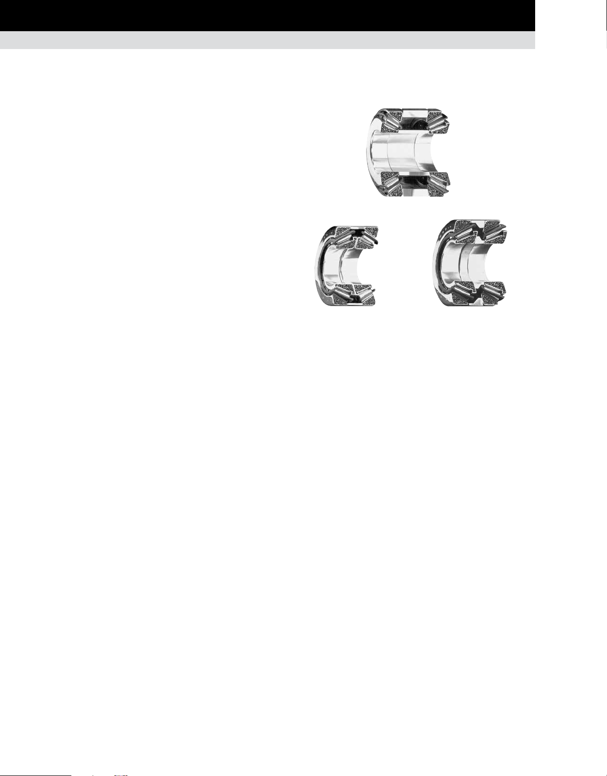
SPHERICAL ROLLER BEARING CAGES
BEARING SELECTION PROCESS
CAGES • SPHERICAL ROLLER BEARING CAGES
STAMPED-STEEL CAGES
The redesigned Timken® EJ bearings incorporate a unique
stamped-steel cage design.
The EJ design includes two independent cages, one for each
row of rollers, which are assembled into an individual bearing.
This feature serves to prevent cage bending when the operating
environment is favorable for this to occur.
This cage is guided on the inner ring and runs above pitch. Each
cage is surface hardened (nitrided) to provide improved wear
resistance as well as additional strength to allow the bearing to
operate in even the most severe environment. Face slots have
been designed for improved lubrication flow. This can result in a
lower operating temperature and longer bearing life.
EJ
Fig. 40. EJ bearing.
EJ
Fig. 41. EJ cage.
PIN-TYPE CAGES
Large diameter spherical roller bearings can be supplied with
these cages. Pin-type cages, one for each row of rollers, consist
of two rings and a series of pins running through the center of
the rolling element. The design of pin-type cages permits an
increased roller complement, giving the bearing enhanced loadcarrying ability. Consult your Timken engineer for suggestions on
the application of this cage.
MACHINED-BRASS CAGE
EM, EMB, YM, YMB and YMD bearing cages are precisionmachined from brass as shown in figs. 44-46. Their rugged
construction provides an advantage in more severe applications.
The open-end, finger-type design permits lubricant to reach all
surfaces easily, ensuring ample lubrication and a cooler running
bearing.
EM/YM YMD
Fig. 43. Machined cages.
EMB/YMB
EM, EMB, YM and YMB are all one-piece designs that are
differentiated by their means of guidance within the bearing. With
EM and YM designs, the cage mass is low and the rollers are used
for guidance, while EMB and YMB cage designs typically have
more mass and guide on the inner ring.
YMD cages are similar to YMB, except they have a two-piece
design. Two independent cages, one for each row of rollers, are
assembled into an individual bearing. This allows each row of
rollers to rotate independently when required by the application,
and prevents bending of the cage fingers.
Fig. 42. Pin-type cage.
Fig. 44. One-piece,
machined-brass,
roller-riding,
finger-type cage.
Fig. 45. One-piece,
machined-brass,
land-riding,
finger-type cage.
TIMKEN ENGINEERING MANUAL
Fig. 46. Split,
machined-brass,
land-riding,
finger-type cage.
29
Page 32

BEARING SELECTION PROCESS
CAGES • CYLINDRICAL ROLLER BEARING CAGES
CYLINDRICAL ROLLER BEARING CAGES
STAMPED-STEEL CAGES
Stamped-steel cages for cylindrical roller bearings consist of
low-carbon steel and are manufactured using a series of cutting,
forming, and punching operations. These cages are made in a
variety of different designs and are suitable for most general
purpose cylindrical roller bearing applications. One specific type
is the S-type design for the 5200 series cylindrical roller bearing,
which is a land-riding cage piloted on the outer ring ribs. This
design has depressed cage bridges which evenly space the
rolling elements and retain them on the outer ring. Stampedsteel cages are easily mass produced and can be used in hightemperature and harsh-lubricant environments.
Fig. 47. S-type cage.
MACHINED CAGES
Machined cages are an option for smaller cylindrical bearing
sizes, and are typically made from brass. Machined cage designs
for cylindrical roller bearings offer increased strength for more
demanding applications.
PIN-TYPE CAGES
Pin-type cages for cylindrical roller bearings consist of two rings
and a series of pins running through the center of the rolling
elements. These cages are used for large diameter cylindrical
roller bearings where machined brass cages are not available.
With this design, additional rollers can typically be added,
resulting in increased load capacity.
Fig. 48. Pin-type cage.
Designs can be one-piece or two-piece cages. One-piece designs
can be either a finger-type as shown in fig. 49 or a standard cage
configuration having fully milled pockets. The one-piece fingertype and the two-piece design with cage ring (fig. 50) are more
common in standard cylindrical roller bearings. They also are
roller-guided designs.
The one-piece version with fully milled roller pockets (fig. 51)
is our premium cage. This cage is used with our EMA series
bearings. Unlike traditional roller-riding cages, it is a land-riding
cage which minimizes drag on the roller elements. This reduces
heat generation, resulting in improved bearing life. Compared to
a two-piece design, this one-piece cage also reduces heat and
wear by enhancing lubrication flow.
Fig. 49. One-piece
finger-type cage.
Fig. 50. Two-piece
brass cage.
Fig. 51. One-piece
premium cage.
TIMKEN ENGINEERING MANUAL
30
Page 33

BALL BEARING CAGES
BEARING SELECTION PROCESS
CAGES • BALL BEARING CAGES
PRESSED-STEEL WELDED CAGES
This cage type consists of two formed
cage halves welded together. This type
of cage is standard for most radial nonfilling-slot ball bearings and provides
high strength and rigidity as well as good
uniformity of ball to pocket clearance.
It is suitable for very high-temperature
applications, but does not accommodate
application misalignment.
Fig. 52. Pressed-steel
welded cage.
MOLDED-NYLON FINGER-TYPE CAGES
These types of cages consist of a one-
piece molded design. Rolling elements
simply snap into place. These cages
are molded of Nylon 66 which is heat
stabilized and moisture conditioned.
This cage type is used in the majority
of wide inner ring (WIR) ball bearings.
The polymer can withstand continuous
Fig. 53. Molded-nylon
cage.
lubricating material with good resistance to abrasion, wear, most
solvents, oils, and greases. This cage type can accommodate
application misalignment.
operating temperatures up to 120° C
(250° F) with spikes up to 150° C (300° F)
and provides a non-corrosive, self-
MACHINED PHENOLIC-TYPE CAGES
Cages of this type are a one-piece design and are usually ring
piloted. The cage is light weight, has oil-absorbing capability, and
is suitable for high-speed applications. Cages of this type can be
precisely machined, which reduces inertial ball and cage impact
forces at high speeds. It does not provide for retention of the balls
for handling purposes.
BRASS- AND STEEL-TYPE CAGES
Ball bearing cages made of brass or steel are designed for heavily
loaded applications. Cage design variations include one-piece
machined-steel or machined-brass and two-piece riveted cast
brass. Most designs are ring piloted. Cages of this type also can
be silver plated for applications requiring high reliability. The
silver plating provides lubrication at the ball-cage interface during
start-up to prevent skidding of the balls.
Fig. 55. Cast-brass cage.
Fig. 56. Machined-brass cage.
Care also needs to be exercised when using aggressive lubrications with extreme-pressure (EP) additives in combination with
elevated temperatures greater than 107° C (225° F).
MOLDED REINFORCED NYLON-TYPE CAGES
These types of cages are one-piece
outer-ring-piloted or ball guided. Cages of
this type are molded out of Nylon 66 with
30 percent glass fiber added for moisture
dimensional stability. The polymer
can withstand continuous operating
temperatures up to 120° C (250° F)
with spikes up to 150° C (300° F)
and provides a non-corrosive, selflubricating material with good resistance
to abrasion, wear, most solvents, oils,
and greases.
Care also needs to be exercised when using aggressive lubrications with extreme-pressure (EP) additives in combination with
elevated temperatures greater than 107° C (225° F).
Fig. 54. Reinforced
nylon cage.
TIMKEN ENGINEERING MANUAL
31
Page 34

BEARING SELECTION PROCESS
DETERMINATION OF APPLIED LOADS AND BEARING ANALYSIS
DETERMINATION OF APPLIED LOADS AND BEARING ANALYSIS
SUMMARY OF SYMBOLS USED TO DETERMINE APPLIED LOADS AND BEARING ANALYSIS
Symbol Description Units (Metric/Inch System)
a Axial Distance from Inner Ring Backface to
Effective Load Center mm, in.
a
Reliability Life Factor unitless
1
a
Material Life Factor unitless
2
a
Operating Condition Life Factor unitless
3
a
Debris Life Factor unitless
3d
a
Load Zone Life Factor unitless
3k
a
Lubrication Life Factor unitless
3l
a
Low-Load Life Factor unitless
3p
a
Effective Bearing Spread mm, in.
e
A, B, … Bearing Position (used as subscripts) unitless
B Outer Ring Width mm, in.
B
Inner Ring Width mm, in.
1
b Tooth Length mm, in.
c
, c2 Linear Distance (positive or negative). mm, in.
1
C Basic Dynamic Radial Load Rating of a Double-Row N, lbf
Bearing for an L
C
Basic Dynamic Thrust Load Rating of a Single-Row
a90
Bearing for an L
3000 Hours at 500 RPM N, lbf
C
Basic Static Radial Load Rating N, lbf
o
C
Basic Static Axial Load Rating N, lbf
oa
C
Basic Dynamic Radial Load Rating of a Single-Row
90
C
90(2)
C
Basic Dynamic Axial Load Rating N, lbf
a
C
Geometry Factor (used in a3l equation) unitless
g
C
Load Factor (used in a3l equation) unitless
l
C
Load Zone Factor (used in a3l equation) unitless
j
C
Speed Factor (used in a3l equation) unitless
s
C
Viscosity Factor (used in a3l equation) unitless
v
C
Grease Lubrication Factor (used in a3l equation) unitless
gr
Bearing for an L
Basic Dynamic Radial Load Rating of a Double-Row
Bearing for an L
of One Million Revolutions
10
of 90 Million Revolutions or
10
of 90 Million Revolutions N, lbf
10
of 90 Million Revolutions N, lbf
10
Cp Specific Heat of Lubricant J/(Kg - °C), BTU/(lbf - °F)
C
Basic Thrust Dynamic Load Rating N, lbf
t
d Bearing Bore Diameter mm, in.
d Ball Diameter mm, in.
d
Spherical Diameter mm, in.
1
d
Shaft Shoulder Diameter mm, in.
a
d
Mean Inner Ring Diameter mm, in.
0
dc Distance Between Gear Centers mm, in.
dm Mean Bearing Diameter mm, in.
d
Shaft Inside Diameter mm, in.
si
D Bearing Outside Diameter mm, in.
D
Tapered Roller Bearing Outer Ring
0
Mean Raceway Diameter mm, in.
Dh Housing Outside Diameter mm, in.
Dm Mean Diameter or Effective Working Diameter
of a Sprocket, Pulley, Wheel or Tire mm, in.
Dm Tapered Roller Mean Large Rib Diameter mm, in.
Symbol Description Units (Metric/Inch System)
Dm
Mean or Effective Working Diameter of the Gear mm, in.
G
Dm
Effective Working Diameter of the Pinion mm, in.
P
Dm
Effective Working Diameter of the Worm mm, in.
W
Dp
Pitch Diameter of the Gear mm, in.
G
Dp
Pitch Diameter of the Pinion mm, in.
P
Dp
Pitch Diameter of the Worm mm, in.
W
e Life Exponent unitless
e Limiting Value of Fa/Fr for the Applicability of
Different Values of Factors X and Y unitless
E Free Endplay mm, in.
f Lubricant Flow Rate L/min, U.S. pt/min
f
Viscous Dependent Torque Coefficient unitless
0
f
Load Dependent Torque Coefficient unitless
1
f
Belt or Chain Pull N, lbf
b
f
Speed Factor unitless
n
f
Combined Load Factor unitless
2
f
Combined Load Factor unitless
3
F General Term for Force N, lbf
F
, F2, …, Fn Magnitudes of Applied Force During a Loading Cycle N, lbf
1
F
Applied Thrust (Axial) Load N, lbf
a
F
Induced Thrust (Axial) Load Due to Radial Loading N, lbf
ai
F
Induced Thrust (Axial) Load Due to Centrifugal Loading N, lbf
ac
F
Thrust Force on Gear N, lbf
aG
F
Thrust Force on Pinion N, lbf
aP
F
Thrust Force on Worm N, lbf
aW
F
Allowable Axial Load N, lbf
az
F
Belt or Chain Pull N, lbf
b
F
Load Term for Torque Equation N, lbf
β
Fc Centrifugal Force N, lbf
F
Applied Radial Load N, lbf
r
F
Resultant Horizontal Force N, lbf
rh
F
Resultant Separating Force N, lbf
RS
F
Resultant Vertical Force N, lbf
RV
F
Separating Force on Gear N, lbf
S
Fs
Separating Force on Gear N, lbf
G
Fs
Separating Force on Pinion N, lbf
P
Fs
Separating Force on Worm N, lbf
W
F
Tangential Force N, lbf
t
F
Tractive Effort on Vehicle Wheels N, lbf
te
F
Tangential Force on Gear N, lbf
tG
F
Tangential Force on Pinion N, lbf
tP
F
Tangential Force on Worm N, lbf
tW
F
Force of Unbalance N, lbf
W
F
Weighted Average Load N, lbf
WB
G Gear (used as subscript) unitless
G
Geometry Factor from Bearing Data Tables unitless
1
G
Geometry Factor from Bearing Data Tables unitless
2
H Power kW, hp
H
Housing Shoulder Inner Diameter mm, in.
s
TIMKEN ENGINEERING MANUAL
32
Page 35

BEARING SELECTION PROCESS
DETERMINATION OF APPLIED LOADS AND BEARING ANALYSIS
Symbol Description Units (Metric/Inch System)
HFs Static Load Rating Adjustment Factor for
Raceway Hardness unitless
i Number of Rows of Rollers in a Bearing unitless
i
Number of Bearing Rows Taking Load unitless
B
k Centrifugal Force Constant lbf/RPM
k1 Bearing Torque Constant unitless
k
, k5, k6 Dimensional Factor to Calculate Heat Generation unitless
4
K Tapered Roller Bearing K-factor; ratio of
basic dynamic radial load rating to basic dynamic
thrust rating in a single-row bearing unitless
K Ball Bearing Constant Based on Geometry
K
, K2 Super Precision K-Factors unitless
1
K
Radial Runout of Outer Ring Assembly mm, in.
ea
K
Outer Ring Contour Radius Expressed
o
K
Inner Ring Contour Radius Expressed
i
as a Decimal Fraction of the Ball Diameter decimal fraction
as a Decimal Fraction of the Ball Diameter decimal fraction
Kia Radial Runout of Inner Ring Assembly mm, in.
K
K-factor for Bearing #n unitless
N
K
Relative Thrust Load Factor – Ball Bearings unitless
T
L
Lead – Axial Advance of a Helix for One Complete
H
Revolution mm, in.
L Distance Between Bearing Geometric Center Lines mm, in.
L
Bearing Life revolutions or hours
10
L
Life Factor unitless
f
m Gearing Ratio unitless
M Bearing Operating Torque N-m, N-mm, lb.-in.
M
Moment N-m, N-mm, lb.-in.
O
n Bearing Operating Speed or General Term
for Speed rot/min, RPM
n
, n2,…, nn Rotation Speeds During a Loading Cycle rot/min, RPM
1
N
Reference Speed rot/min, RPM
A
n
Gear Operating Speed rot/min, RPM
G
n
Pinion Operating Speed rot/min, RPM
P
n
Worm Operating Speed rot/min, RPM
W
N
Number of Rotations of the Ball and Cage Assembly unitless
c
N
Number of Rotations of the Inner Ring unitless
i
N
Number of Teeth in the Gear unitless
G
N
Number of Teeth in the Pinion unitless
P
N
Number of Teeth in the Sprocket unitless
S
N
Speed Factor unitless
f
P Pinion (used as subscript) unitless
P
Static Equivalent Load N, lbf
o
P
Static Equivalent Thrust (Axial) N, lbf
oa
P
Static Equivalent Radial Load N, lbf
or
P
Dynamic Equivalent Axial Load N, lbf
a
P
Dynamic Equivalent Radial Load N, lbf
r
P
Equivalent Dynamic Load N, lbf
eq
Q Generated Heat or Heat Dissipation Rate W, BTU/min
Q
Generated Heat W, BTU/min
gen
Q
Heat Dissipated by a Circulating Oil System W, BTU/min
oil
r Radius to Center of Mass mm, in.
R Percent Reliability, Used in the Calculation
of the a
Factor unitless
1
Symbol Description Units (Metric/Inch System)
RIC Radial Internal Clearance mm, in.
S Shaft Diameter mm, in.
s Shaft (used as subscript) unitless
S
Inner Ring Reference Face Runout mm, in.
d
2
S
Outside Cylindrical Surface Runout mm, in.
D
S
Axial Runout of Outer Ring Assembly mm, in.
ea
S
Axial Runout of Inner Ring Assembly mm, in.
ia
t
, t2, …, tN Fractions of Time During a Loading Cycle unitless
1
T Applied Thrust (Axial) Load N, lbf
T
Equivalent Thrust Load N, lbf
E
v Vertical (used as subscript) unitless
V Linear Velocity or Speed km/h, mph
V
Inner Ring Width Variation mm, in.
BS
V
Outer Ring Width Variation mm, in.
CS
Vr Rubbing, Surface or Tapered Roller Bearing
Rib Velocity m/s, fpm
W Worm (used as subscript) unitless
X Dynamic Radial Load Factor unitless
X
Static Radial Load Factor unitless
0
Y, Y
, Y2, ... Dynamic Thrust (Axial) Load Factor unitless
1
Y
Static Thrust (Axial) Load Factor unitless
0
Z Number of Rolling Elements unitless
a
Coefficient of Linear Expansion mm/mm/°C, in./in./°F
T
a
Tapered Roller Bearing Half Included
o
Outer Ring Raceway Angle deg.
a Ball Bearing Nominal Contact Angle deg.
ΔT Temperature Difference Between Shaft/Inner Ring/
Rollers and Housing/Outer Ring °C, °F
Δ
Inner Ring Width Deviation mm, in.
Bs
Δ
Outer Ring Width Deviation mm, in.
Cs
Δ
Deviation of Mean Bore Diameter in a Single Plane mm, in.
dmp
Δ
Deviation of Mean Outside Diameter in a Single Plane mm, in.
Dmp
ds Interference Fit of Inner Ring on Shaft mm, in.
dh Interference Fit of Outer Ring in Housing mm, in.
η Efficiency, Decimal Fraction
q
, q2, q3 Gear Mesh Angles Relative to the Reference Plane deg., rad
1
qi, qo Oil Inlet or Outlet Temperature °C, °F
l Worm Gear Lead Angle deg.
m Coefficient of Friction unitless
m Lubricant Dynamic Viscosity cP
v Lubricant Kinematic Viscosity cSt
s
Approximate Maximum Contact Stress MPa, psi
o
Φ
Normal Tooth Pressure Angle for the Gear deg.
G
Φ
Normal Tooth Pressure Angle for the Pinion deg.
P
Ψ
Helix (Helical) or Spiral Angle for the Gear deg.
G
Ψ
Helix (Helical) or Spiral Angle for the Pinion deg.
P
r Lubricant Density kg/m
ΥG Bevel Gearing – Gear Pitch Angle deg.
Hypoid Gearing – Gear Root Angle deg.
Υ
Bevel Gearing – Pinion Pitch Angle deg.
P
Hypoid Gearing – Pinion Face Angle deg.
3
, lb./ft
3
TIMKEN ENGINEERING MANUAL
33
Page 36

BEARING SELECTION PROCESS
DETERMINATION OF APPLIED LOADS AND BEARING ANALYSIS • GEARING
GEARING
The following equations are used to determine the forces
developed by machine elements commonly encountered in
bearing applications.
SPUR GEARING
Tangential force
x 10
x 10
7
G
5
G
) H
) H
(metric system)
(inch system)
FtG =
(1.91
DpG n
(1.26
DpG n
=
Separating force
FsG = FtG tan
ΦG
Fig. 57. Spur gearing.
SINGLE HELICAL GEARING
STRAIGHT BEVEL AND ZEROL GEARING WITH
ZERO DEGREES SPIRAL
In straight bevel and zerol gearing, the gear forces tend to push
the pinion and gear out of mesh, such that the directions of the
thrust and separating forces are always the same regardless of
direction of rotation (fig. 59). In calculating the tangential force
(F
or FtG) for bevel gearing, the pinion or gear mean diameter
tP
(Dm
or DmG) is used instead of the pitch diameter (DpP or DpG).
P
The mean diameter is calculated as follows:
Dm
G = DpG -
In straight bevel and zerol gearing:
F
= F
tP
b sin
ΥG or DmP
tG
= DpP - b sin
Fig. 59. Straight bevel
and zerol gears.
ΥP
Tangential force
(1.91
FtG =
x 10
DpG n
(1.26
=
x 10
DpG n
Thrust force
FaG = FtG tan Ψ
Separating force
F
tan Φ
FsG =
cos Ψ
tG
7
) H
G
5
) H
G
G
G
G
(metric system)
(inch system)
Fig. 58. Helical gearing.
PINION
Tangential force
FtP =
(1.91
DmP n
=
DmP n
(1.26
x 10
x 10
Thrust force
FaP = FtP tan
ΦP
Separating force
FsP = FtP tan
ΦP
7
) H
P
5
) H
P
sin
cos
ΥP
ΥP
(metric system)
(inch system)
TIMKEN ENGINEERING MANUAL
34
Page 37

STRAIGHT BEVEL GEAR
Tangential force
7
x 10
x 10
) H
G
5
) H
G
FtG =
DmG n
DmG n
(1.91
(1.26
=
Thrust force
(metric system)
(inch system)
BEARING SELECTION PROCESS
DETERMINATION OF APPLIED LOADS AND BEARING ANALYSIS • GEARING
Fig. 60. Straight bevel gearing.
F
tG
FaG = FtG tan
ΦG
sin
ΥG
Separating force
FsG = FtG tan
ΦG
cos
ΥG
SPIRAL BEVEL AND HYPOID GEARING
In spiral bevel and hypoid gearing, the directions of the thrust
and separating forces depend upon spiral angle, hand of spiral,
direction of rotation, and whether the gear is driving or driven (see
fig. 61). The hand of the spiral is determined by noting whether the
tooth curvature on the near face of the gear (fig. 62) inclines to the
left or right from the shaft axis. Direction of rotation is determined
by viewing toward the gear or pinion apex.
In spiral bevel gearing:
F
In hypoid gearing:
F
cos Ψ
= F
tP
=
tP
tG
F
cos ΨP
tG
G
Fig. 61. Spiral bevel
and hypoid gears.
Hypoid pinion effective working diameter:
N
Dm
N
= Dm
P
G
( )(
p
G
cos Ψ
cos Ψ
G
)
P
Tangential force
7
x 10
x 10
G
5
G
) H
) H
G
(metric system)
(inch system)
FtG =
DmG n
DmG n
Hypoid gear effective working diameter:
Dm
(1.91
(1.26
=
= DpG - b sin Υ
G
Fig. 62. Spiral bevel
and hypoid gearing.
TIMKEN ENGINEERING MANUAL
35
Page 38

BEARING SELECTION PROCESS
DETERMINATION OF APPLIED LOADS AND BEARING ANALYSIS • GEARING
TABLE 2. SPIRAL BEVEL AND HYPOID BEARING EQUATIONS
Driving Member Rotation Thrust Force Separating Force
Driving member Driving member
Right-hand spiral
clockwise
or
Left-hand spiral
counterclockwise
Right-hand spiral
counterclockwise
or
Left-hand spiral
clockwise
FtP
FaP =
cos Ψ
FtG
FaG =
cos Ψ
FtP
FaP =
cos Ψ
FtG
FaG =
cos Ψ
(tan Φ
sin Υ
– sin Ψ
+ sin Ψ
+ sin Ψ
– sin Ψ
cos ΥP)
P
cos ΥG)
G
cos ΥP)
P
cos ΥG)
G
P
G
G
P
sin Υ
sin Υ
sin Υ
P
G
P
G
P
Driven member Driven member
(tan Φ
G
Driving member Driving member
(tan Φ
P
Driven member Driven member
(tan Φ
G
FtP
FsP =
cos Ψ
FtG
FsG =
cos Ψ
FtP
FsP =
cos Ψ
FtG
FsG =
cos Ψ
STRAIGHT WORM GEARING
Worm
(tan Φ
cos ΥP + sin Ψ
P
P
(tan Φ
cos Υ
– sin Ψ
G
P
cos Υ
G
cos Υ
G
P
+ sin Ψ
G
G
(tan Φ
P
(tan Φ
G
– sin Ψ
sin ΥP)
P
sin ΥG)
G
sin ΥP)
P
sin ΥG)
G
Tangential force
(1.91
F
tW
=
x 10
DPW n
(1.26
=
x 10
DpW n
Thrust force
F
aW
=
x 10
(1.91
DpG n
(1.26
=
x 10
DpG n
or
F
η
tW
F
tan
aW
=
λ
Separating force
Fs
=
W
F
tW
cos Φ sin
7
) H
W
5
) H
W
7
) H η
G
5
) H η
G
sin Φ
λ +
(metric system)
(inch system)
(metric system)
(inch system)
μ cos
λ
Fig. 63. Straight worm gearing.
TIMKEN ENGINEERING MANUAL
36
Page 39

BEARING SELECTION PROCESS
DETERMINATION OF APPLIED LOADS AND BEARING ANALYSIS • GEARING
Worm Gear
Tangential force
x 10
x 10
η
tW
λ
(1.91
x 10
(1.26
x 10
tW
-1
(
-1
(
Dp
W nW
-14
W nW
7
) H η
G
5
) H η
G
7
) H
W
5
) H
W
sin Φ
μ cos
λ +
Dp
G
W
L
H
W
μ tan
3
r
3
) V
+
r
λ
(metric system)
(inch system)
(metric system)
(inch system)
λ
)
)
λ
λ
0.146
+
λ
- 0.103
0.09
r
(meters per second)
0.235
- 0.103
0.09
r
(feet per minute)
(1.91
F
DpG n
=
DpG n
or
F
tan
Thrust force
F
DpW n
DpW n
Separating force
Fs
cos Φ sin
Where:
λ
m Dp
or
λ
π Dp
and
η =
cos Φ + μ cot
Metric system
μ
V
Vr =
(1.91 x 10⁴) cos
Inch system
μ
V
Vr =
3.82 cos
(1)
Approximate coefficient of friction for the 0.015 to 15 m/s (3 to 3000 ft/min)
rubbing velocity range.
=
tG
(1.26
F
=
tG
=
aG
=
F
=
G
= tan
= tan
cos Φ –
(1)
= (5.34 x 10 -7) V
(1)
= (7 x 10
Dp
DOUBLE ENVELOPING WORM GEARING
Worm
Tangential force
(1.91
F
DmW n
=
DmW n
Thrust force
F
Separating force
Fs
cos
=
tW
= 0.98 F
aW
=
W
(1.26
0.98 F
7
x 10
) H
(metric system)
W
5
x 10
) H
(inch system)
W
Use this value for FtG for bearing
loading calculations on worm gear
tG
shaft. For torque calculations, use
the following FtG equations.
tan Φ
tG
λ
Worm Gear
Tangential force
x 10
x 10
x 10
x 10
x 10
x 10
tan Φ
tG
λ
Dp
-1
(
7
) H m η
(metric system)
W
5
) H m η
(inch system)
W
7
) H η
(metric system)
G
5
) H η
(inch system)
G
7
) H
W
5
) H
W
(metric system)
(inch system)
G
G
) (
W
= tan
-1
(1.91
F
DpG n
=
DpG n
or
F
DpG n
=
DpG n
Thrust force
F
DmW n
=
DmW n
Separating force
Fs
cos
Where:
η = efficiency (refer to manufacturer’s catalog)
Dm
Lead angle at center of worm:
λ
m Dp
=
tG
(1.26
(1.91
=
tG
(1.26
(1.91
=
aG
(1.26
0.98 F
=
G
= 2dc -0.98 Dp
W
= tan
Use this value
for calculating
torque in
subsequent gears
and shafts. For
bearing loading
calculations, use
the equation
for F
aW.
L
H
Dp
)
W
TIMKEN ENGINEERING MANUAL
37
Page 40

BEARING SELECTION PROCESS
DETERMINATION OF APPLIED LOADS AND BEARING ANALYSIS
SHOCK LOADS
Belt and chain drive factors
Due to the variations of belt tightness as set by various operators,
an exact equation relating total belt pull to tension F
side and tension F
on the slack side (fig. 64) is difficult to establish.
2
The following equation and table 3 may be used to estimate the
total pull from various types of belt and pulley, and chain and
sprocket designs:
x 10
7
) H B
(metric system)
(1.91
F
=
b
Dm n
x
(1.26
=
105) H B
(inch system)
Dm n
Standard roller chain sprocket mean diameter.
sin
P
180
( )
s
Dm =
N
Where:
P = chain pitch
D
m
= Tension, slack side
F
2
F
b
on the tight
1
It is difficult to determine the exact effect that shock loading has
on bearing life. The magnitude of the shock load depends on the
masses of the colliding bodies, their velocities and deformations
at impact.
The effect on the bearing depends on how much of the shock is
absorbed between the point of impact and the bearing, as well as
whether the shock load is great enough to cause bearing damage.
It also is dependent on frequency and duration of shock loads.
As a minimum, a suddenly applied load is equivalent to twice its
static value. It may be considerably more than this, depending
on the velocity of impact.
Shock involves a number of variables that generally are not
known or easily determined. Therefore, it is good practice to
rely on experience. Timken has years of experience with many
types of equipment under the most severe loading conditions.
Your Timken engineer should be consulted on any application
involving unusual loading or service requirements.
CENTRIFUGAL FORCE
Centrifugal force resulting from imbalance in a rotating member:
F
r n2
w
F
=
c
8.94 x 10
F
r n
=
w
3.52 x 10
5
2
4
metric system)
(
(inch system)
F
= Tension, tight side
1
Fig. 64. Belt or chain drive.
TABLE 3. BELT OR CHAIN PULL FACTOR
BASED ON 180 DEGREES ANGLE OF WRAP
Type
Chains, single .................................. 1.00
Chains, double ................................. 1.25
“V” belts............................................. 1.50
TRACTIVE EFFORT AND WHEEL SPEED
Tractive effort is the tangential force between the driving wheels
and the road necessary to propel a vehicle at a given speed
against the combined grade, air and rolling resistance. The
relationships of tractive effort, power, wheel speed and vehicle
B
speed are:
H =
H =
and
n =
n =
Fte V
3600
F
V
te
375
5300V
D
m
336V
D
m
TIMKEN ENGINEERING MANUAL
38
Page 41

BEARING REACTIONS
Effective bearing
spread
Effective bearing
spread
Effective bearing
spread
Effective bearing
spread
Effective bearing
spread
For a shaft on two supports, bearing radial loads are determined
by:
Defining the bearing effective spread.
•
Resolving forces applied to the shaft into horizontal and ver-
•
tical components, relative to a convenient reference plane.
Summing moments about the effective center of each of
•
the bearing supports, and solving for the radial and axial
reactions at each support.
EFFECTIVE SPREAD
TAPERED ROLLER OR ANGULAR CONTACT
BALL BEARINGS
When a load is applied to a tapered roller or angular contact
ball bearing, the internal forces at each rolling element-to-outer
raceway contact act normal to the raceway. These forces
have radial and axial components. With the exception of the
special case of pure axial loads, the inner ring and the shaft
will experience moments imposed by the asymmetrical axial
components of the forces on the rolling elements. The effective
center for tapered roller bearings is defined as the point at which
the lines of force normal to the outer ring raceway intersect the
bearing axis. As an approximation, it also applies to angular
contact ball bearings. The effective spread is then defined as the
distance between the bearing effective centers for a two-bearing
system. It can be demonstrated mathematically that, if the shaft is
modeled as being supported at its effective bearing center rather
than at its geometric bearing center, the bearing moment may be
ignored when calculating radial loads on the bearing.
Only externally applied loads need to be considered, and moments
are taken about the effective centers of the bearings to determine
loads or reactions.
BEARING SELECTION PROCESS
BEARING REACTIONS • EFFECTIVE SPREAD
Fig. 65 shows single-row bearings in a direct and indirect
mounting configuration. The choice of whether to use direct or
indirect mounting depends upon the application.
SPHERICAL ROLLER BEARINGS
The effective center for each row of spherical rollers intersects
the shaft axis at the bearing geometric center as shown in fig.
66. As the distance between effective centers for each row of
a bearing is zero (i.e. zero moment arm), a pure couple cannot
be generated internal to the bearing. Therefore, when a shaft
and housing are misaligned, the inner and outer rings of the
bearing rotate up to a few degrees relative to each other,
without creating internal forces. This self-aligning capability in
turn prevents an external moment load from being supported
by the bearing. Therefore, spherical roller bearings can only
accommodate external shaft and housing loads through radial
and axial reaction forces.
Effective bearing spread
Float position Fixed position
Fig. 66. Spherical roller bearing.
Effective bearing
spread
Indirect Mounting – Tapered Roller Bearings
Back-to-Back/DB – Angular Contact Ball Bearings
Effective bearing
spread
Effective bearing
spread
Fig. 65. Choice of mounting
configuration for single-row
bearings, showing position of
effective load-carrying centers.
Effective bearing
spread
Direct Mounting – Tapered Roller Bearings
Face-to-Face/DF – Angular Contact Ball Bearings
TIMKEN ENGINEERING MANUAL
39
Page 42

BEARING SELECTION PROCESS
BEARING REACTIONS • FORCE RESOLUTION
FORCE RESOLUTION
SHAFTS ON TWO SUPPORTS
Simple beam equations are used to translate the externally
applied forces on a shaft into bearing reactions acting at the
bearing effective centers.
The following equations are for the case of a shaft on two
supports with gear forces F
(thrust), an external radial load F, and an external moment M
The loads are applied at arbitrary angles (θ
to the reference plane indicated in fig. 67. Using the principle of
superposition, the equations for vertical and horizontal reactions
(F
and Frh) can be expanded to include any number of gears,
rv
external forces or moments. For the bearing reaction calculations,
the gear forces should include the sign (+/-) generated from the
respective gear force equation.
F
sG
F
F
tG
aG
F
θ
2
1
3
Reference
Plane of Moment
θ
θ
Plane of
(tangential), Fs (separating), and Fa
t
, θ2, and θ3) relative
1
F
sG
F
aG
Bearing A
F
F
rA
rA
h
v
F
tG
F
Bearing B
M
o
c
1
c
2
a
e
o
F
rB
h
F
rB
v
Care should be used when doing this to ensure proper supporting
degrees of freedom are used. That is, tapered roller bearings
and ball bearings support radial loads, moment loads and thrust
loads in both directions. Spherical roller bearings will not support
a moment load, but will support radial and thrust loads in both
directions. Cylindrical roller bearings support radial and moment
loading, but can only support slight thrust loads depending upon
.
thrust flange configuration.
SHAFT ON THREE OR MORE SUPPORTS
The equations of static equilibrium are insufficient to solve
bearing reactions on a shaft having more than two supports.
Such cases can be solved using computer programs if adequate
information is available. In such problems, the deflections of the
shaft, bearings and housings affect the distribution of loads. Any
variance in these parameters can significantly affect bearing
reactions.
Fig. 67. Bearing radial reactions.
Vertical reaction component at bearing position B:
a
1
F
=
rB
v
c1 (FsG cos θ1 + FtG sin θ1) +
(
2
e
1
(D
pG
Horizontal reaction component at bearing position B:
ae 2
1
F
=
rB
c1 (FsG sin θ1 - FtG cos θ1) +
h
(
1
(DpG - b sin γG) FaG sin θ1 +c2 F sin θ2 + M sin θ
Vertical reaction component at bearing position A:
F
= FsG cos θ1 + FtG sin θ1 + F cos θ2 - F
rA
v
rB
v
Horizontal reaction component at bearing position A:
F
Resultant radial reaction: FrA = [(F
Resultant axial reaction: F
= FsG sin θ1 - FtG cos θ1 + F sin θ2 - F
rA
h
rA
= F
aA
aG
rB
h
)2 + (F
v
2
)
rA
h
(fixed position) FaB = O (float position)
- b sin γG) FaG cos θ1 +c2 F cos θ2 + M cos θ
1/2
FrB = [(F
]
rB
)2 + (F
v
1/2
2
)
rB
]
h
3
(
3
(
TIMKEN ENGINEERING MANUAL
40
Page 43

BEARING REACTIONS • DYNAMIC EQUIVALENT RADIAL BEARING LOADS (Pr)
DYNAMIC EQUIVALENT RADIAL
BEARING LOADS (Pr)
To calculate the L10 life, it is necessary to calculate a dynamic
equivalent radial load, designated by P
radial load is defined as a single radial load that, if applied to the
bearing, will result in the same life as the combined loading under
which the bearing operates. For all bearing types, the equation
takes the following form:
P
= XFr + YF
r
a
SPHERICAL ROLLER BEARINGS
For spherical roller bearings, the values for Pr can be determined
using the equations below. Calculate the ratio of the axial load to
the radial load. Compare this ratio to the e value for the bearing.
In equation form,
P
= F
+ YF
r
r
P
= 0.67F
r
Values for e and Y are available in the Spherical Roller Bearing Catalog available on
www.timken.com.
r
a
+ YF
for Fa / F
for Fa / F
a
CYLINDRICAL ROLLER BEARINGS
For cylindrical roller bearings with purely radial applied load:
P
= Fr
r
The maximum dynamic radial load that may be applied to a cylindrical roller bearing
should be < C/3.
If, in addition to the radial load, an axial load Fa acts on the bearing,
this axial load is taken into consideration when calculating the
life of a bearing (with F
TABLE 4. CYLINDRICAL ROLLER BEARING
DYNAMIC EQUIVALENT RADIAL VALUES
Dimension Series Load Ratio
10.. 2..E, 3..E
22..E, 23..E
< Faz; Faz is the allowable axial load).
a
Fa/Fr < 0.11
Fa/Fr > 0.11
Fa/Fr < 0.17
Fa/Fr > 0.17
. The dynamic equivalent
r
e, and
r
> e.
r
Equivalent Load
P = 0.93 Fr + 0.69 F
P = 0.93 Fr + 0.45 F
Dynamic
P = F
r
P = F
r
a
a
BEARING SELECTION PROCESS
RADIAL AND ANGULAR CONTACT BALL
BEARINGS
For ball bearings, the dynamic equivalent radial load equations
can be found in table 5. The required Y factors are found in table
6 on page 42.
TABLE 5. DYNAMIC EQUIVALENT RADIAL LOAD EQUATIONS
RADIAL AND ANGULAR CONTACT BEARINGS
Bearing
Description (ref.)
Bearing Type
and or Series
RADIAL TYPE BALL BEARINGS Use Larger Of Resulting Pr Value
M9300K,MM9300K
M9100K,MM9100K
M200K,MM200K
M300K,MM300K
Small inch and metric
9300,9100,200,300
and derivatives
XLS large inch
W and GW Tri-Ply
Wide inner ring ball
bearing housed units
ANGULAR CONTACT BALL BEARINGS Use Larger Of Resulting Pr Value
7200K, 7200W
7300W, 7400W
5200K-5300W
5311W-5318W
5218W, 5220W, 5407W
5221W, 5214W
5200, 5200W
(see 20° exceptions)
5300, 5300W
(see 20° exceptions)
5400, 5400W
(see 20° exceptions)
7200WN
7300WN
7400WN
2M9300WI
2MM9100WI
2M200WI, 2MM200WI
2MM300WI
2MM9100WO
3M9300WI
3M9100WI, 3MM9100WI
3M200WI, 3MM200WI
3MM300WI
(1)
If Pr > Co or Pr > 1/2 CE consult with your Timken engineer on life calculations.
FOR BALL BEARINGS
Contact
Angle
0°
0°
0°
20°
30°
40°
15°
25°
Single-Row
and Tandem
Mountings
K
= F
T
iBC
Pr = Fr
or
Pr = 0.56Fr + Y1F
Pr = Fr
or
Pr = 0.56Fr + Y1F
Pr = Fr
or
Pr = 0.56Fr + Y1F
= Fr
P
r
or
Pr = 0.43Fr + F
Pr = Fr
or
Pr = 0.39Fr +0.76F
Pr = F
r
or
Pr = 0.35Fr +0.57F
Pr = Fr
or
Pr = 0.44Fr +Y2F
Pr = Fr
or
Pr = 0.44Fr + Y3F
Pr = Fr
or
Pr = 0.41Fr +0.87F
and Preload Pair
a
o
Pr = Fr + 1.20Y1Fa
Pr = 0.78Fr + 1.625Y1F
a
a
a
Pr = Fr + 1.09F
Pr = 0.70Fr + 1.63F
a
Pr = Fr + 0.78F
Pr = 0.63Fr + 1.24F
a
Pr = Fr + 0.55F
Pr = 0.57Fr + 0.93F
a
Pr = Fr + 1.124Y2F
Pr = 0.72Fr + 1.625Y2F
a
Pr = Fr + 1.124Y3F
Pr = 0.72Fr + 1.625Y3F
a
Pr = Fr + 0.92F
Pr = 0.67Fr + 1.41F
a
Double-Row
Mountings
KT = F
a
C
o
(1)
or
or
or
or
or
or
or
a
a
a
a
a
a
a
a
a
a
a
a
a
TIMKEN ENGINEERING MANUAL
41
Page 44

BEARING SELECTION PROCESS
BEARING REACTIONS • DYNAMIC EQUIVALENT RADIAL BEARING LOADS (Pr)
FOR BALL BEARING DYNAMIC EQUIVALENT RADIAL LOADS
TABLE 6. REQUIRED Y FACTORS
K
T
0.015 2.30 1.47 1.60
0.020 2.22 1.44 1.59
0.025 2.10 1.41 1.57
0.030 2.00 1.39 1.56
0.040 1.86 1.35 1.55
0.050 1.76 1.32 1.53
0.060 1.68 1.29 1.51
0.080 1.57 1.25 1.49
0.100 1.48 1.21 1.47
0.120 1.42 1.19 1.45
0.150 1.34 1.14 1.42
0.200 1.25 1.09 1.39
0.250 1.18 1.05 1.35
0.300 1.13 1.02 1.33
0.400 1.05 1.00 1.29
0.500 1.00 1.00 1.25
0.600 — — 1.22
0.800 — — 1.17
1.000 — — 1.13
1.200 — — 1.10
Y
1
Y
2
Y
3
TAPERED ROLLER BEARINGS
Tapered roller bearings are designed to carry radial loads, thrust
loads or any combination of the two. Because of the tapered
design of the raceways, a radial load will induce a thrust reaction
within the bearing, which must be opposed by an equal or greater
thrust load to keep the inner ring and outer ring from separating.
The induced thrust adds to or subtracts from any externally
applied thrust loads, depending upon the direction of the applied
thrust load. As a result, the seated bearing sees the induced thrust
of the opposing bearing plus the external thrust. The unseated
bearing sees only its own induced thrust.
The ratio of the radial to the thrust load and the bearing included
outer ring angle determine the load zone in a given bearing. The
number of rollers in contact as a result of this ratio defines the
load zone. If all the rollers are in contact, the load zone is referred
to as being 360 degrees.
When only radial load is applied to a tapered roller bearing, for
convenience it is assumed in using the traditional calculation
method that half the rollers support the load – the load zone is
180 degrees. In this case, induced bearing thrust is:
0.47 F
F
a(180)
=
The basic dynamic radial load rating, C90, is assumed to be the
radial load-carrying capacity with a 180-degree load zone in the
bearing. When the thrust load on a bearing exceeds the induced
thrust, F
, a dynamic equivalent radial load must be used to
a(180)
calculate bearing life.
r
K
TIMKEN ENGINEERING MANUAL
42
The equations in tables 7 and 8 provide approximations of the
dynamic equivalent radial load assuming a 180-degree load zone
in one bearing and 180 degrees or more in the opposite bearing.
Page 45

BEARING REACTIONS • DYNAMIC EQUIVALENT RADIAL BEARING LOADS (Pr)
Bearing A
F
rA
F
rB
F
ae
Bearing B
F
rA
F
rB
F
ae
Bearing A
Bearing B
Single-row mounting
To use this table for a single-row mounting, determine if bearings
are direct or indirect mounted and to which bearing, A or B, thrust
F
is applied. Once the appropriate design is established, follow
ae
across the page opposite that design, and check to determine
which thrust load and dynamic equivalent radial load equations
apply.
TABLE 7. DYNAMIC EQUIVALENT RADIAL LOAD EQUATIONS, SINGLE-ROW TAPERED ROLLER BEARING MOUNTING
Design Thrust Condition Axial Load
BEARING SELECTION PROCESS
Dynamic Equivalent
Radial Load
F
rA
F
rA
Bearing A
F
ae
Bearing A
F
rA
Bearing A
Bearing A
Bearing B
F
rB
Bearing B
F
ae
F
rB
Design Thrust Condition Axial Load
Bearing B
F
ae
Bearing B
F
rB
Dynamic Equivalent
Radial Load
F
ae
F
rA
(1)
If PA < FrA, use PA = FrA or if PB < FrB, use PB = F
F
rB
rB.
TIMKEN ENGINEERING MANUAL
43
Page 46

BEARING SELECTION PROCESS
F
rC
F
rAB
Bearing A
Bearing B
F
ae
Fixed Bearing
Floating Bearing
Bearing C
F
rC
F
rAB
Bearing A
Bearing B
F
rAB
Bearing B
F
ae
Fixed Bearing
F
ae
Fixed Bearing
Floating Bearing
Floating Bearing
Bearing C
F
rC
Bearing C
Bearing A
F
rC
F
rAB
Bearing A
Bearing B
F
ae
Fixed Bearing
Floating Bearing
Bearing C
F
rC
F
rAB
Bearing A
Bearing B
F
rAB
Bearing B
F
ae
Fixed Bearing
F
ae
Fixed Bearing
Floating Bearing
Floating Bearing
Bearing C
F
rC
Bearing C
Bearing A
BEARING REACTIONS • DYNAMIC EQUIVALENT RADIAL BEARING LOADS (Pr)
Double-row mounting, fixed or floating, similar
bearing series
For double-row tapered roller bearings, the following table can
be used. In this table, only bearing A has an applied thrust load.
If bearing B has the applied thrust load, the A’s in the equations
should be replaced by B’s and vice versa.
TABLE 8. DYNAMIC EQUIVALENT RADIAL LOAD EQUATIONS, DOUBLE-ROW TAPERED ROLLER BEARING MOUNTING
Design – Similar Bearing Series Thrust Condition
F
Bearing A
Bearing A
rAB
Fixed Bearing
F
rAB
Fixed Bearing
Bearing B
Bearing B
F
ae
F
ae
F
rC
Bearing C
Floating Bearing
F
rC
Bearing C
Floating Bearing
F
≤
ae
0.6 F
F
>
ae
0.6 F
For double-row similar bearing series with no external thrust,
F
=0, the dynamic equivalent radial load, Pr, equals F
ae
Since F
or FrC is the radial load on the double-row assembly,
rAB
the double-row basic dynamic radial load rating, C
used to calculate bearing life.
Dynamic Equivalent
Radial Load
P
K
K
rAB
rAB
P
P
P
A =
B =
A =
B =
0.5 F
0.5 F
0.4 F
0
+ 0.83 K
rAB
- 0.83 K
rAB
+ K
rAB
A Fae
A Fae
A Fae
rAB
, is to be
90(2)
or FrC.
NOTE: F
Design – Dissimilar Bearing Series Thrust Condition
Bearing A
F
rAB
F
rAB
Bearing A
Bearing B
Bearing B
Fixed Bearing
Fixed Bearing
is the radial load on the double-row assembly. The single-row basic dynamic radial load rating, C90, is to be applied when calculating life based on the above equations.
rAB
F
ae
F
ae
F
rC
Floating Bearing
F
rC
Floating Bearing
Bearing C
Bearing C
0.6 F
≤
0.6 F
>
rAB
rAB
F
ae
KA
F
ae
KA
P
=
A
P
B =
KA + KB
Dynamic Equivalent
K
A
KA + KB
K
B
P
0.4 F
A =
P
0
B =
Radial Load
(F
+ 1.67 KB Fae)
rAB
(F
- 1.67 KA Fae)
rAB
+ K
rAB
A Fae
TIMKEN ENGINEERING MANUAL
44
Page 47

BEARING SELECTION PROCESS
BEARING REACTIONS • DYNAMIC EQUIVALENT THRUST BEARING LOADS (Pa) • STATIC RADIAL AND AXIAL EQUIVALENT LOADS
DYNAMIC EQUIVALENT THRUST
BEARING LOADS (Pa)
For thrust ball, thrust spherical and thrust tapered roller
bearings, the existence of radial loads introduces complex load
calculations that must be carefully considered. If the radial load
is zero, the equivalent dynamic thrust load (P
the applied thrust load (F
). If any radial load is expected in the
a
) will be equal to
a
application, consult your Timken engineer for advice on bearing
selection.
THRUST ANGULAR CONTACT BALL BEARINGS
For thrust angular contact ball bearings, the dynamic equivalent
thrust load is determined by:
P
= Xr F + YF
a
a
The minimum permissible thrust load to radial load ratios (Fa/Fr),
X factors and Y factors are listed in the bearing dimension tables
in the Thrust Bearing Catalog available on www.timken.com.
THRUST SPHERICAL ROLLER BEARINGS
Thrust spherical roller bearing dynamic loads are determined by:
Pa = 1.2Fr + F
Radial load (Fr) of a thrust spherical roller bearing is proportional
to the applied axial load (F
roller angle induces a thrust load (F
is applied. This thrust load must be resisted by another thrust
bearing on the shaft or by an axial load greater than F
a
) such that Fr 0.55 Fa. The steep
a
= 1.2Fr) when a radial load
ai
.
ai
For all bearings, the maximum contact stress can be approximated
using the static equivalent load and the static rating.
For roller bearings:
σ
σ
= 4000
o
= 580
o
P
o
( )
C
o
1/2
P
o
( )
C
o
For ball bearings:
1/2
MPa
σ
ksi
σ
= 4200
0
= 607
0
P
o
( )
C
1/3
P
o
( )
C
o
1/3
MPa
o
ksi
SPHERICAL ROLLER, RADIAL BALL AND
ANGULAR CONTACT BALL BEARINGS
The load factors Xo and Yo, listed in table 9, are used with the
following equation to estimate the static radial equivalent load.
P
= Xo Fr + Yo F
or
a
THRUST BALL BEARINGS
Similar to radial ball bearings, thrust ball bearings use the same
equation for equivalent static and dynamic loading.
P
= Xo Fr + Yo F
oa
a
The X and Y factors are listed in the Thrust Bearing Catalog
available on www.timken.com along with the minimum required
thrust load-to-radial load ratio for maintaining proper operation.
THRUST SPHERICAL ROLLER BEARINGS
STATIC RADIAL AND AXIAL
EQUIVALENT LOADS
To compare the load on a non-rotating bearing with the basic
static capacity, it is necessary to determine the static equivalent
load. The static equivalent load is defined as the pure radial or
thrust load, whichever is appropriate, that produces the same
contact pressure in the center of the most heavily stressed rolling
element as the actual combined load. The static equivalent radial
and/or axial loading is dependent on the bearing type selected. For
bearings designed to accommodate only radial or thrust loading,
the static equivalent load is equivalent to the applied load.
The following equation is used for thrust spherical roller bearings:
P
= Fa + 2.7 F
oa
r
Thrust spherical roller bearings require a minimum thrust load
for proper operation. P
should not be greater than 0.5 Coa. If
oa
conditions exceed this, consult your Timken engineer.
TABLE 9. VALUES OF XO AND YO
FOR STATICALLY STRESSED RADIAL BEARINGS
Bearing Type
Radial Ball 0.6 0.5 0.6 0.5
Angular Contact Ball 15 0.5 0.47 1 0.94
Spherical Roller 0.5 0.22 cota 1 0.44 cota
Contact
Angle
(a)
20 0.5 0.42 1 0.84
25 0.5 0.38 1 0.76
30 0.5 0.33 1 0.66
35 0.5 0.29 1 0.58
40 0.5 0.26 1
Single-Row Double-Row
X
TIMKEN ENGINEERING MANUAL
Y
o
X
o
o
Y
o
45
Page 48

BEARING SELECTION PROCESS
BEARING REACTIONS • STATIC RADIAL AND AXIAL EQUIVALENT LOADS • MINIMUM BEARING LOAD
TAPERED ROLLER BEARINGS
To determine the static equivalent radial load for a single-row
mounting, first determine the thrust load, (F
), then use the
a
equations in this section, depending on the appropriate thrust
load condition.
The bearing data tables do not include static ratings for doublerow bearings. The double-row static radial rating can be
estimated as:
C
o(2)
= 2C
TABLE 10. STATIC EQUIVALENT LOAD EQUATIONS, SINGLE-ROW TAPERED ROLLER BEARING
Design Thrust Condition Axial Load
Bearing A
F
F
rA
Bearing A
F
rA
Design (external axial load, Fae,
onto bearing A)
Use the values of PO calculated for comparison with the static rating (CO), even if PO is less than the radial applied Fr.
Bearing B
0.47 F
K
ae
Bearing B
F
rB
0.47 F
K
F
ae
F
rB
0.47 F
rA
≤
A KB
rA >
A KB
0.47 F
rB
rB
+ F
ae
+ F
ae
0.47 F
F
=
aA
aB
aA
aB
0.47 F
=
0.47 F
=
0.47 F
=
K
K
K
K
F
F
F
rB
B
rB
B
rA
A
rA
A
o
Static Equivalent
Radial Load
P
= F
OB
rB
+ F
ae
- F
ae
for FaA < 0.6 FrA / K
P
= 1.6 FrA - 1.269 KA F
OA
for FaA > 0.6 FrA / K
P
= 0.5 FrA + 0.564 KA F
OA
for FaB > 0.6 FrB / K
P
= 0.5 FrB + 0.564 KB F
OB
for FaB < 0.6 FrB / K
P
= 1.6 FrB - 1.269 KB F
OB
P
= F
OA
rA
A
aA
A
aA
B
aB
B
aB
MINIMUM BEARING LOAD
Slippage can occur if loads are too light and, if accompanied by
inadequate lubrication, may cause damage to the bearings. The
minimum load for radial cylindrical and spherical roller bearings
is P
= 0.04 C.
r
Centrifugal force in thrust spherical roller bearings tends to propel
the rollers outward. The bearing geometry converts this force to
another induced thrust component, which must be overcome by
an axial load. This induced thrust (F
F
46
= k n2 x 10
ac
TIMKEN ENGINEERING MANUAL
-5
(pounds force per RPM)
) is given by:
ac
The minimum required working thrust load on a thrust spherical
roller bearing (F
F
a min
= 1.2 F
) is then computed by:
a min
C
0a
r + Fac
1000
(lbf)
In addition to meeting the above calculated value, the minimum
required working thrust load (F
than 0.1 percent of the static thrust load rating (C
) should be equal to or greater
a min
).
0a
Page 49

BEARING SELECTION PROCESS
BEARING RATINGS • DYNAMIC LOAD RATING • STATIC LOAD RATING
BEARING RATINGS
There are two fundamental load ratings for bearings, a dynamic load rating and a static load rating.
The dynamic load rating is used to estimate the life of a rotating bearing. Static load ratings are
used to determine the maximum permissible load that can be applied to a non-rotating bearing.
DYNAMIC LOAD RATING
Published dynamic load ratings for Timken bearings are typically
based on a rated life of one million revolutions. This rating,
designated as C, is defined as the radial load under which a
population of bearings will achieve an L
revolutions. For Timken tapered roller bearings, the dynamic
load rating is more commonly based on a rated life of 90 million
revolutions, with the designation of C
load under which a population of bearings will achieve an L
of 90 million revolutions. For tapered roller bearings, the dynamic
thrust rating also is published and is designated as C
rating is the thrust load under which a population of bearings will
achieve an L
The dynamic load rating of a bearing is a function of the internal
bearing geometry, which includes raceway angles, contact length
between rolling elements and raceways, and the number and size
of rolling elements. It also is a function of material cleanliness.
life of 90 million revolutions.
10
life of one million
10
. This rating is the radial
90
10
. The C
a90
life
a90
STATIC LOAD RATING
The basic static radial load rating and thrust load rating for
Timken bearings are based on a maximum contact stress within
a non-rotating bearing of 4000 MPa (580 ksi) for roller bearings
and 4200 MPa (609 ksi) for ball bearings, at the center of contact
on the most heavily loaded rolling element.
The 4000 MPa (580 ksi) or 4200 MPa (609 ksi) stress levels may
cause visible light Brinell marks on the bearing raceways. This
degree of marking will not have a measurable effect on fatigue
life when the bearing is subsequently rotating under a lower
application load. If sound, vibration or torque are critical, or if a
pronounced shock load is present, a lower load limit should be
applied. For more information on selecting a bearing for static
load conditions, consult your Timken engineer.
TIMKEN ENGINEERING MANUAL
47
Page 50

BEARING SELECTION PROCESS
BEARING RATINGS • BEARING LIFE • RATING LIFE • BEARING LIFE EQUATIONS
BEARING LIFE
Many different performance criteria exist that dictate how a
bearing should be selected. These include bearing fatigue life,
rotational precision, power requirements, temperature limits,
speed capabilities, sound, etc. This section deals primarily with
bearing life as related to material-associated fatigue. Bearing
life is defined as the length of time, or number of revolutions,
until a fatigue spall of 6 mm
is a statistical phenomenon, the life of an individual bearing
is impossible to predetermine precisely. Bearings that may
appear to be identical can exhibit considerable life scatter when
tested under identical conditions. Thus it is necessary to base
life predictions on a statistical evaluation of a large number
of bearings operating under similar conditions. The Weibull
distribution function is the accepted standard for predicting the
life of a population of bearings at any given reliability level.
2
(0.01 in.2) develops. Since fatigue
RATING LIFE
Rating life, (L10), is the life that 90 percent of a group of apparently
identical bearings will complete or exceed before a fatigue spall
develops. The L
for a single bearing under a certain load.
life also is associated with 90 percent reliability
10
BEARING LIFE EQUATIONS
Traditionally, the L10 life has been calculated as follows for
bearings under radial or combined loading, where the dynamic
equivalent radial load, P
load rating is based on one million cycles:
e
C
L10 =
or
L10 =
For thrust bearings, the above equations change
to the following.
L
or
L10 =
( )
P
r
e
C
( ) ( )
P
r
C
a
=
10
( )
P
a
e
C
a
( ) ( )
P
a
has been determined and the dynamic
r,
(1x10⁶)
1x10⁶
60n
e
(1x10⁶)
1x10⁶
60n
revolutions
hours
revolutions
hours
Tapered roller bearings often use a dynamic load rating based
on 90 million cycles, as opposed to one million cycles, changing
the equations as follows:
10/3
C
L
or
L10 =
and
L
or
L10 =
The traditional form of the equations based on dynamic load
ratings of one million cycles is most common and will, therefore,
be used throughout the rest of this section. The dynamic
equivalent load equations and the life adjustment factors defined
in subsequent sections are applicable to all forms of the life
equation.
With increased emphasis on the relationship between the
reference conditions and the actual environment in which the
bearing operates in the machine, the traditional life equations
have been expanded to include certain additional variables that
affect bearing performance. The approach whereby these factors
are considered in the bearing analysis and selection has been
termed Bearing Systems Analysis (BSA).
The ABMA expanded bearing life equation is:
L
The Timken expanded bearing life equation is:
L
P
Where:
e = 3 for ball bearings
=
roller bearings
90
=
10
( )
P
r
10/3
C
90
( )
P
r
10/3
C
a90
=
10
( )
P
a
10/3
C
a90
( )
P
a
= a1a2a3L
na
= a1a2a3da3ka3la3ma
na
10
10
/3 for tapered, cylindrical and spherical
(90x106)
90x106
( )
60n
(90x106) revolutions
90x106
60n
3p
( )
revolutions
hours
hours
e
C
(1x10
r
6
) revolutions
e = 3 for ball bearings
10
=
/3 for tapered, cylindrical and spherical
roller bearings
TIMKEN ENGINEERING MANUAL
48
Page 51

BEARING SELECTION PROCESS
BEARING RATINGS • BEARING LIFE EQUATIONS
RELIABILITY LIFE FACTOR (a1)
Reliability, in the context of bearing life for a group of apparently
identical bearings operating under the same conditions, is the
percentage of the group that is expected to attain or exceed
a specified life. The reliability of an individual bearing is the
probability that the bearing will attain or exceed a specified life.
The reliability life adjustment factor is:
2/3
100
a
= 4.26 ln
1
ln = natural logarithm (base e)
To adjust the calculated L10 life for reliability, multiply by the
a
factor. If 90 (90 percent reliability) is substituted for R in the
1
above equation, a
0.25. The following table lists the reliability factor for commonly
used reliability values.
TABLE 11. RELIABILITY FACTORS
R (percent) L
90 L10 1.00
95 L
96 L
97 L
98 L
99 L
99.5 L
99.9 L
Note that the equation for reliability adjustment assumes there
is a short minimum life below which the probability of bearing
damage is minimal (e.g., zero probability of bearing damage
producing a short life). Extensive bearing fatigue life testing has
shown the minimum life, below which the probability of bearing
damage is negligible, to be larger than predicted using the above
adjustment factor. For a more accurate prediction of bearing lives
at high levels of reliability, consult your Timken engineer.
( )
= 1. For R = 99 (99 percent reliability), a1 =
1
+ 0.05
R
n
0.64
5
0.55
4
0.47
3
0.37
2
0.25
1
0.175
0.5
0.093
0.1
a
1
that contact stresses are approximately less than 2400 MPa (350
ksi), and adequate lubrication is provided. It is important to note
that improvements in material cannot offset poor lubrication in
an operating bearing system. Consult your Timken engineer for
applicability of the material factor.
DEBRIS LIFE FACTOR (a3d)
Debris within a lubrication system reduces the life of a roller
bearing by creating indentations on the contacting surfaces,
leading to stress risers. The Timken life rating equations were
developed based on test data obtained with 40 μm oil filtration, and
measured ISO cleanliness levels of approximately 15/12, which is
typical of cleanliness levels found in normal industrial machinery.
When more or less debris is present within the system, the fatigue
life predictions can be adjusted according to the measured or
expected ISO lubricant cleanliness level to more accurately
reflect the expected bearing performance.
A more accurate option for predicting bearing life in a debris
environment is to perform a Debris Signature Analysis™.
The Debris Signature Analysis is a process for determining
the effects of the actual debris present in your system on the
bearing performance. The typical way in which this occurs is
through measurements of dented/bruised surfaces on actual
bearings run in a given application. This type of analysis can be
beneficial because different types of debris cause differing levels
of performance degradation. Soft, ductile particles can cause
differing levels of performance degradation than hard, brittle
particles. Hard, ductile particles are typically most detrimental to
bearing life. Brittle particles can break down, thus not affecting
performance to as large of a degree as hard ductile particles. For
more information on Debris Signature Analysis or the availability
of debris-resistant bearings for your application, consult your
Timken engineer.
MATERIAL LIFE FACTOR (a2)
The life adjustment factor for bearing material, a2, for standard
Timken bearings manufactured from bearing quality steel is 1.0.
Bearings also are manufactured from premium steels, containing
fewer and smaller inclusion impurities than standard steels
and providing the benefit of extending bearing fatigue life (e.g.,
DuraSpexx
requires that fatigue life is limited by nonmetallic inclusions,
®
bearing). Application of the material life factor
Fig. 68. Surface map of a bearing raceway with debris denting.
TIMKEN ENGINEERING MANUAL
49
Page 52

BEARING SELECTION PROCESS
BEARING RATINGS • BEARING LIFE EQUATIONS
LOAD ZONE LIFE FACTOR (a3k)
Bearing fatigue life is a function of the stresses between rolling
elements and raceways as well as the number of stress cycles
the bearing surfaces experience per revolution. Stresses are
influenced by the magnitude of the applied load, the internal
bearing geometry and the number of rolling elements supporting
the load. The number of stress cycles is a function of the number
of rollers supporting the load, which, in turn, is influenced by the
number of rollers per row, the bearing geometry, applied load
and bearing setting.
The arc defined by the rollers supporting the load is called the
bearing load zone. The load zone is significantly influenced
by bearing setting or internal clearance, either radial or axial
depending on the bearing type. Neglecting preload, less clearance
in a bearing results in a larger load zone and subsequently longer
bearing life.
The dynamic equivalent load (P
load (F
) to approximate the combined load zone effect on L
r
If a more accurate assessment of the load zone adjusted life is
necessary (e.g., including the effects of internal clearance or
fitting practice), consult your Timken engineer.
) is used instead of the applied
r
10a
LUBRICATION LIFE FACTOR (a3l)
The influence of lubrication film on bearing performance is related
to the reduction or prevention of asperity (metal-metal) contact
between the bearing surfaces. Extensive testing has been done
at The Timken Technology Center to quantify the effects of the
lubrication-related parameters on bearing life. It has been found
that the roller and raceway surface finish, relative to lubricant
film thickness, has the most notable effect on improving bearing
performance. Factors such as bearing geometry, material, loads
and load zones also play an important role in bearing performance.
The following equation provides a method to calculate the
lubrication factor for a more accurate prediction of the influence
of lubrication on bearing life (L
a
= Cg Cl Cj Cs Cv C
3l
The a3l maximum is 2.88 for all bearings. The a3l minimum is 0.200
for case-carburized bearings and 0.126 for through-hardened
.
bearings.
A lubricant contamination factor is not included in the lubrication
factor because Timken endurance tests are typically run with a
40 μm filter to provide a realistic level of lubricant cleanness for
most applications.
):
10a
gr
Fig. 69. Bearing load zones and roller-raceway contact loading.
Geometry factor (Cg)
Cg is given for most part numbers that are available in the bearing
catalogs on www.timken.com. The geometry factor also includes
the material effects and load zone considerations for non-tapered
roller bearings, as these also are inherent to the bearing design.
However, it should be noted that the primary effect of the load
zone is on roller load distributions and contact stresses within
the bearing, which are not quantified within the lubrication factor.
Refer to the previous section Load Zone Life Factor (a
information.
The geometry factor (C
) is not applicable to our DuraSpexx™
g
product. For more information on our DuraSpexx product, consult
your Timken engineer.
) for more
3k
TIMKEN ENGINEERING MANUAL
50
Page 53

BEARING SELECTION PROCESS
BEARING RATINGS • BEARING LIFE EQUATIONS
Load factor (C
)
l
The Cl factor can be obtained from fig. 70. Note that the factor is
different based on the type of bearing utilized. P
is the equivalent
r
load applied to the bearing in Newtons and is determined in the
Dynamic Equivalent Bearing Loads (P
) section.
r
1.0
0.9
0.8
0.7
0.6
l
0.5
C
0.4
0.3
Ball Bearings
Roller Bearings
0.2
0.1
0.0
1 10 100 1000 10000 100000 1000000 10000000
Pr (Newtons)
Fig. 70. Load factor (Cl) vs. dynamic equivalent bearing load (Pr).
1
Load zone factor (Cj)
For all non-tapered roller bearings, the load zone factor is one
(1). For tapered roller bearings, the load zone factor can be taken
from fig. 71.
0.9
0.8
j
C
0.7
0.6
0.5
0 0.5 1 1.5 2 2.5
F
r
Fa K
0.747
Fig. 71. Load zone factor (Cj) for tapered roller bearings.
TIMKEN ENGINEERING MANUAL
51
Page 54

BEARING SELECTION PROCESS
C
v
BEARING RATINGS • BEARING LIFE EQUATIONS
Speed factor (Cs)
Cs can be determined from fig. 72, where rev/min
(RPM) is the rotational speed of the inner ring relative
to the outer ring.
Fig. 72. Speed factor (Cs) vs.
rotational speed.
Viscosity factor (Cv)
The lubricant kinematic viscosity (centistokes
[cSt]) is taken at the operating temperature of the
bearing. The operating viscosity can be estimated
by fig. 73. The viscosity factor (C
determined from figs. 73 and 74 shown here.
) can then be
v
1000
Ball Bearings
Roller Bearings
100
C
10
1
1 1 0 100 1000 10000
Rotational Speed (RPM)
10000
1000
100
ISO VG
680
460
320
220
150
100
68
46
32
Fig. 73. Temperature vs.
kinematic viscosity.
10
Kinematic Viscosity (cSt)
1
0 50 100 150 200
1000
Temperature (˚C)
Ball Bearings
Roller Bearings
100
10
Fig. 74. Viscosity factor (C
) vs.
v
kinematic viscosity.
1
1 1 0 100 1000 10000
Kinematic Viscosity (cSt)
TIMKEN ENGINEERING MANUAL
52
Page 55

GREASE LUBRICATION FACTOR (Cgr)
Over time, grease degradation causes a reduction in lubricant
film thickness. Consequently, a reduction factor (C
used to adjust for this effect.
) should be
gr
BEARING SELECTION PROCESS
BEARING RATINGS • BEARING LIFE EQUATIONS
C
= 0.79
gr
LOW-LOAD LIFE FACTOR (a3p)
Bearing life tests show greatly extended bearing fatigue life
performance is achievable when the bearing contact stresses
are low and the lubricant film is sufficient to fully separate the
micro-scale textures of the contacting surfaces. Mating the
test data with sophisticated computer programs for predicting
bearing performance, Timken engineers developed a low-load
factor to predict the life increase expected when operating under
low-bearing loads. Fig. 75 shows the low-load factor (a
function of the lubricant life factor (a
) and the ratio of bearing
3l
dynamic rating to the bearing equivalent load.
6.5
C/P
=13.48
=13.48
C/P
r
r
6
C/P
C/P
5.5
5
4.5
4
3.5
3
2.5
2
1.5
1
0.5
0 0.5 1 1.5 2 2.5 3
C/P
=9.63 C/P
=9.63 C/P
r
r
=7.7 C/P
=7.7 C/P
C/P
r
r
=6.74
=6.74
r
r
) as a
3p
=5.78
=5.78
r
r
C/P
C/P
r
r
=3.5
=3.5
C/P
C/P
C/P
C/P
C/P
C/P
C/P
C/P
C/P
C/P
=5.12
=5.12
r
r
=4.81
=4.81
r
r
=4.24
=4.24
r
r
=3.85
=3.85
r
r
=3.08
=3.08
r
r
Fig. 75. Low-load life adjustment factor.
TIMKEN ENGINEERING MANUAL
53
Page 56

BEARING SELECTION PROCESS
BEARING RATINGS • BEARING LIFE EQUATIONS
MISALIGNMENT LIFE FACTOR (a3m)
Accurate alignment of the shaft relative to the housing is critical for
bearing performance. As misalignment increases under moderate
to heavy loads, high contact stresses can be generated at the
edges of contact between the raceway and rolling element. Special
profiling of the raceway or rolling element can in most cases offset
the effects of misalignment as shown in fig. 76. This figure shows
the roller-to-inner ring contact stress of a tapered roller bearing
under a misaligned condition with and without special profiling.
The profiling significantly reduces the edge stress, resulting in
improved bearing performance. The misalignment factor takes
into account the effects of profiling on bearing life.
For tapered roller bearings, the base or reference condition upon
which the bearing rating is generated includes a misalignment of
0.0005 radians. Above this misalignment value, reduction in life
can be expected and will be reflected in the misalignment factor.
For cylindrical roller bearings, the misalignment factor is also a
measure of the effect of bearing axial load on life. Axial loading
of the bearing causes a moment to be generated about the roller
center, thus shifting the roller-raceway contact stresses toward
the end of the roller, similar to bearing misalignment.
Maximum recommended misalignment values for cylindrical roller
bearings having profiled rollers are listed in the following table.
TABLE 12. CYLINDRICAL ROLLER BEARING
MAXIMUM MISALIGNMENT RECOMMENDATIONS
Maximum Recommended Misalignment
Load as %C
mrad Degrees
<20 1.2 0.07
20-35 0.5 0.03
>35 Check with your Timken engineer.
Inner Raceway Contact Stress with Misalignment
700
600
500
400
300
Stress (ksi)
200
100
0
700
600
500
400
300
Stress (ksi)
200
100
0
A. Raceway length
No special profile
B. Raceway length
Special profile
Fig. 76. Tapered roller bearing contact stress under misaligned
condition.
The misalignment factor for spherical roller bearings is 1.0 due
to the self-aligning capabilities of a spherical roller bearing. The
allowable misalignment of a spherical roller bearing is between
0.5 and 1.25 degrees, depending on the bearing series as noted in
table 13. Life will be reduced if these limits are exceeded.
Performance of all Timken bearings under various levels of
misalignment and radial and axial load can be predicted using
sophisticated computer programs. Using these programs,
Timken engineers can design special bearing-contact profiles
to accommodate the conditions of radial load, axial load and/or
bearing misalignment in your application. Consult your Timken
engineer for more information.
TIMKEN ENGINEERING MANUAL
54
TABLE 13. SPHERICAL ROLLER BEARING
MAXIMUM MISALIGNMENT RECOMMENDATIONS
Bearing Series Maximum Misalignment (Degrees)
238 ±0.5
222, 230, 231, 239, 249 ±0.75
223, 240 ±1
232, 241 ±1.25
Page 57

BEARING SELECTION PROCESS
SYSTEM LIFE AND WEIGHTED AVERAGE LOAD AND LIFE • SYSTEM LIFE • WEIGHTED AVERAGE LOAD AND LIFE EQUATIONS
SYSTEM LIFE AND WEIGHTED AVERAGE LOAD AND LIFE
SYSTEM LIFE
System reliability is the probability that all of the given bearings
in a system will attain or exceed some required life. System
reliability is the product of the individual bearing reliabilities in
the system:
R
In the application, the L10 system life for a number of bearings
each having different L
L
= RA RB RC…. R
(system)
10(system)
10
= [(1/L
life is:
3/2
)
10A
n
+ (1/L
10B
3/2
)
+ ….(1/L
10n
3/2]-2/3
)
WEIGHTED AVERAGE LOAD
AND LIFE EQUATIONS
In many applications, bearings are subjected to various conditions
of loading, and bearing selection is often made on the basis of
maximum load and speed. However, under these conditions, a
more meaningful analysis may be made by examining the loading
cycle to determine the weighted average load.
Bearing selection based on weighted average loading will take
into account variations in speed, load, and proportion of time
during which the variable loads and speeds occur. However, it is
still necessary to consider extreme loading conditions to evaluate
bearing contact stresses and alignment.
WEIGHTED AVERAGE LOAD
Variable speed, load and proportion time:
F
= [(n1 t1 F
wt
1
10/3
+ ….nn tn F
Uniformly increasing load, constant speed:
F
= [(3/13) (F
wt
max
13/3
- F
Use of the weighted average load in the bearing life equation
does not take into account the effects of different speeds on the
lubrication factor a
. For load cycles with varying speeds, it is
3l
recommended that life calculations be made for each condition
and that the life for each condition be plugged into the weighted
average life equation.
min
13/3
n
10/3
) / (F
) / na]
max
- F
0.3
0.3
)]
min
WEIGHTED AVERAGE LIFE
L
= 1/{[t1 / (Ln)1]+ [t2 / (Ln)2]+… [tn / (Ln)
nwt
TIMKEN ENGINEERING MANUAL
n
]
}
55
Page 58

BEARING TOLERANCES, METRIC AND INCH SYSTEMS
BEARING TOLERANCES, METRIC AND INCH SYSTEMS
BEARING TOLERANCES, METRIC AND INCH SYSTEMS
Ball and roller bearings are manufactured to a number of
specifications, with each having classes that define tolerances
on dimensions such as bore, O.D., width and runout. In addition,
bearings are produced in both inch and metric systems with the
boundary dimension tolerances being different for these two
systems. The major difference between the two systems is that
inch bearings have historically been manufactured to positive
bore and O.D. tolerances, whereas metric bearings have been
manufactured to corresponding standard negative tolerances.
The following table summarizes the different specifications and
classes for ball, tapered roller, cylindrical roller and spherical
TABLE 14. BEARING SPECIFICATIONS AND CLASSES
System Specification Bearing Type Standard Bearing Class Precision Bearing Class
Metric Timken Tapered Roller Bearings K N C B A AA
ISO/DIN All Bearing Types P0 P6 P5 P4 P2 -
ABMA Cylindrical, Spherical Roller Bearings RBEC 1 RBEC 3 RBEC 5 RBEC 7 RBEC 9 -
Ball Bearings ABEC 1 ABEC 3 ABEC 5 ABEC 7 ABEC 9 -
Tapered Roller Bearings K N C B A -
Inch Timken Tapered Roller Bearings 4 2 3 0 00 000
ABMA Tapered Roller Bearings 4 2 3 0 00 -
roller bearings. For the purposes of this manual, ISO specifications
are shown for ball, cylindrical roller and spherical roller bearings.
Timken specifications are shown for tapered roller bearings.
Boundary dimension tolerances for ball and roller bearing
usage are listed in the following tables. These tolerances are
provided for use in selecting bearings for general applications
in conjunction with the bearing mounting and fitting practices
offered in later sections.
TIMKEN ENGINEERING MANUAL
56
Page 59

BEARING TOLERANCES, METRIC AND INCH SYSTEMS
METRIC SYSTEM
RADIAL BALL, SPHERICAL AND CYLINDRICAL ROLLER BEARINGS
METRIC SYSTEM
Standard Timken® radial ball, radial spherical roller and
radial cylindrical roller bearings maintain normal tolerances
according to the current ISO 492 standard. Tables 15 and 16 list
the critical tolerances for these bearing types. For applications
where running tolerance is critical, P6 or P5 tolerances are
recommended.
The term deviation is defined as the difference between a single
ring dimension and the nominal dimension. For metric tolerances,
the nominal dimension is at a +0 mm (0 in.) tolerance. The deviation
is the tolerance range for the listed parameter. Variation is defined
as the difference between the largest and smallest measurements
of a given parameter for an individual ring.
TABLE 15. RADIAL BALL, SPHERICAL AND CYLINDRICAL ROLLER BEARING TOLERANCES – INNER RING (Metric)
mm
in.
Face
Runout
with Bore
mm
Bearing Bore
Over Incl. P0 P6 P5 P0 P6 P5 P0 P6 P5 P5 P5 P0, P6 P5
mm
in.
2.5000 10.000 -0.008 -0.007 -0.005 0.015 0.015 0.005 0.010 0.006 0.004 0.007 0.007 -0.120 -0.040
0.0984 0.3937 -0.0003 -0.0003 -0.0002 0.0006 0.0006 0.0002 0.0004 0.0002 0.0002 0.0003 0.0003 -0.0047 -0.0157
10.000 18.000 -0.008 -0.007 -0.005 0.020 0.020 0.005 0.010 0.007 0.004 0.007 0.007 -0.120 -0.080
0.3937 0.7087 -0.0003 -0.0003 -0.0002 0.0008 0.0008 0.0002 0.0004 0.0003 0.0002 0.0003 0.0003 -0.0047 -0.0031
18.000 30.000 -0.010 -0.008 -0.006 0.020 0.020 0.005 0.013 0.008 0.004 0.008 0.008 -0.120 -0.120
0.7087 1.1811 -0.0004 -0.0003 -0.0002 0.0008 0.0008 0.0002 0.0005 0.0003 0.0002 0.0003 0.0003 -0.0047 -0.0047
30.000 50.000 -0.012 -0.010 -0.008 0.020 0.020 0.005 0.015 0.010 0.005 0.008 0.008 -0.120 -0.120
1.1811 1.9685 -0.0005 -0.0004 -0.0003 0.0008 0.0008 0.0002 0.0006 0.0004 0.0002 0.0003 0.0003 -0.0047 -0.0047
50.000 80.000 -0.015 -0.012 -0.009 0.025 0.025 0.006 0.020 0.010 0.005 0.008 0.008 -0.150 -0.150
1.9685 3.1496 -0.0006 -0.0005 -0.0004 0.0010 0.0010 0.0002 0.0008 0.0004 0.0002 0.0003 0.0003 -0.0059 -0.0059
80.000 120.000 -0.020 -0.015 -0.010 0.025 0.025 0.007 0.025 0.013 0.006 0.009 0.009 -0.200 -0.200
3.1496 4.7244 -0.0008 -0.0006 -0.0004 0.0010 0.0010 0.0003 0.0010 0.0005 0.0002 0.0004 0.0004 -0.0079 -0.0079
120.000 150.000 -0.025 -0.018 -0.013 0.030 0.030 0.008 0.030 0.018 0.008 0.010 0.010 -0.250 -0.250
4.7244 5.9055 -0.0010 -0.0007 -0.0005 0.0012 0.0012 0.0003 0.0012 0.0007 0.0003 0.0004 0.0004 -0.0098 -0.0098
150.000 180.000 -0.025 -0.018 -0.013 0.030 0.030 0.008 0.030 0.018 0.008 0.010 0.010 -0.250 -0.250
5.9055 7.0866 -0.0010 -0.0007 -0.0005 0.0012 0.0012 0.0003 0.0012 0.0007 0.0003 0.0004 0.0004 -0.0098 -0.0098
180.000 250.000 -0.030 -0.022 -0.015 0.030 0.030 0.010 0.040 0.020 0.010 0.011 0.013 -0.300 -0.300
7.0866 9.8425 -0.0012 -0.0009 -0.0006 0.0012 0.0012 0.0004 0.0016 0.0008 0.0004 0.0004 0.0005 -0.0018 -0.0018
250.000 315.000 -0.035 -0.025 -0.018 0.035 0.035 0.013 0.050 0.025 0.013 0.013 0.015 -0.350 -0.350
9.8425 12.4016 -0.0014 -0.0010 -0.0007 0.0014 0.0014 0.0005 0.0020 0.0010 0.0005 0.0005 0.0006 -0.0138 -0.0138
315.000 400.000 -0.040 -0.030 -0.023 0.040 0.040 0.015 0.060 0.030 0.015 0.015 0.020 -0.400 -0.400
12.4016 15.7480 -0.0016
400.000 500.000 -0.045 -0.035 – 0.050 0.045 – 0.065 0.035 – – – -0.450 –
15.7480 19.6850 -0.0018 -0.0014 – 0.0020 0.0018 – 0.0026 0.0014 – – – -0.0177 –
500.000 630.000 -0.050 -0.040 – 0.060 0.050 – 0.070 0.040 – – – -0.500 –
19.6850 24.8031 -0.0020 -0.0016 – 0.0024 0.0020 – 0.0028 0.0016 – – – -0.0197 –
630.000 800.000 -0.075 – – 0.070 – – 0.080 – – – – -0.750 –
24.8031 31.4961 -0.0030 – – 0.0028 – – 0.0031 – – – – -0.0295 –
(1)
Tolerance range is from +0 to value listed.
mm
in.
Bore Deviation
mm
in.
(1)
Δ
dmp
mm
in.
-0.0012 -0.0009 0.0016 0.0016 0.0006 0.0024 0.0012 0.0006 0.0006 0.0008 -0.0157 -0.0157
mm
in.
Width Variation
mm
in.
V
mm
in.
Radial Runout
BS
mm
in.
mm
in.
K
mm
in.
ia
Axial
Runout
S
in.
S
d
mm
in.
Width Deviation
Inner & Outer Rings
ia
mm
in.
Δ
and Δ
B
s
C
mm
in.
(1)
s
TIMKEN ENGINEERING MANUAL
57
Page 60

BEARING TOLERANCES, METRIC AND INCH SYSTEMS
METRIC SYSTEM
TABLE 16. RADIAL BALL, SPHERICAL AND CYLINDRICAL ROLLER BEARING TOLERANCES – OUTER RING (Metric)
Axial
Runout
S
ea
mm
in.
Bearing O.D.
Outside Deviation
Δ
Dmp
(1)
Width Variation
V
CS
Radial Runout
K
ea
Over Incl. P0 P6 P5 P0 P6 P0 P6 P5 P5 P5
mm
in.
mm
in.
mm
in.
mm
in.
mm
in.
mm
in.
mm
in.
mm
in.
mm
in.
mm
in.
0.000 18.000 -0.008 -0.007 -0.005 0.015 0.005 0.015 0.008 0.005 0.008 0.008
0.0000 0.7087 -0.0003 -0.0003 -0.0002 0.0006 0.0002 0.0006 0.0003 0.0002 0.0003 0.0003
18.000 30.000 -0.009 -0.008 -0.006 0.020 0.005 0.015 0.009 0.006 0.008 0.008
0.7087 1.1811 -0.0004 -0.0003 -0.00024 0.0008 0.0002 0.0006 0.0004 0.00024 0.0003 0.0003
30.000 50.000 -0.011 -0.009 -0.007 0.020 0.005 0.020 0.010 0.007 0.008 0.008
1.1811 1.9685 -0.0004 -0.0004 -0.0003 0.0008 0.0002 0.0008 0.0004 0.0003 0.0003 0.0003
50.000 80.000 -0.013 -0.011 -0.009 0.025 0.006 0.025 0.013 0.008 0.010 0.008
1.9685 3.1496 -0.0005 -0.0004 -0.0004 0.0010 0.00024 0.0010 0.0005 0.0003 0.0004 0.0003
80.000 120.000 -0.015 -0.013 -0.010 0.025 0.008 0.035 0.018 0.010 0.011 0.009
3.1496 4.7244 -0.0006 -0.0005 -0.0004 0.0010 0.0003 0.0014 0.0007 0.0004 0.0004 0.0004
120.000 150.000 -0.018 -0.015 -0.011 0.030 0.008 0.040 0.020 0.011 0.013 0.010
4.7244 5.9055 -0.0007 -0.0006 -0.0004 0.0012 0.0003 0.0016 0.0008 0.0004 0.0005 0.0004
150.000 180.000 -0.025 -0.018 -0.013 0.030 0.008 0.045 0.023 0.013 0.014 0.010
5.9055 7.0866 -0.0010 -0.0007 -0.0005 0.0012 0.0003 0.0018 0.0009 0.0005 0.0006 0.0004
180.000 250.000 -0.030 -0.020 -0.015 0.030 0.010 0.050 0.025 0.015 0.015 0.011
7.0866 9.8425 -0.0012 -0.0008 -0.0006 0.0012 0.0004 0.0020 0.0010 0.0006 0.0006 0.0004
250.000 315.000 -0.035 -0.025 -0.018 0.035 0.011 0.060 0.030 0.018 0.018 0.013
9.8425 12.4016 -0.0014 -0.0010 -0.0007 0.0014 0.0004 0.0024 0.0012 0.0007 0.0007 0.0005
315.000 400.000 -0.040 -0.028 -0.020 0.040 0.013 0.070 0.035 0.020 0.020 0.013
12.4016 15.7480 -0.0016 -0.0011 -0.0008 0.0016 0.0005 0.0028 0.0014 0.0008 0.0008 0.0005
400.000 500.000 -0.045 -0.033 -0.023 0.045 0.015 0.080 0.040 0.023 0.023 0.015
15.7480 19.6850 -0.0018 -0.0013 -0.0009 0.0018 0.0006 0.0031 0.0016 0.0009 0.0009 0.0006
500.000 630.000 -0.050 -0.038 -0.028 0.050 0.018 0.100 0.050 0.025 0.025 0.018
19.6850 24.8031 -0.0020 -0.0015 -0.0011 0.0020 0.0007 0.0039 0.0020 0.0010 0.0010 0.0007
630.000 800.000 -0.075 -0.045 -0.035 – 0.020 0.120 0.060 0.030 0.030 0.020
24.8031 31.4961 -0.0030 -0.0018 -0.0014 – 0.0008 0.0047 0.0024 0.0012 0.0012 0.0008
800.000 1000.000 -0.100 -0.060 – – – 0.140 0.075 – – –
31.4961 39.3701 -0.0040 -0.0024 – – – 0.0055 0.0030 – – –
1000.000
1250.000 -0.125 – – – – 0.160 – – – –
39.3701 49.2126 -0.0050 – – – – 0.0063 – – – –
(1)
Tolerance range is from +0 to value listed.
Outside
Diameter
Runout
With Face
S
D
mm
in.
TABLE 17. THRUST BALL BEARING TOLERANCES – TYPE TVB
Bore O.D. Height
Bearing Bore Tolerance
Over Incl. Over Incl. Over Incl. Max. Min.
mm
in.
mm
in.
0.000 171.450 +0.127 0.000 134.938 -0.051 0.000 46.038 +0.127 -0.127
0.0000 6.7500 +0.0050 0.0000 5.3125 -0.0020 0.0000 1.8125 +0.0050 -0.0050
171.450 508.000 +0.178 134.938 441.325 -0.076 46.038 304.800 +0.254 -0.254
6.7500 20.0000 +0.0070 5.3125 17.3750 -0.0030 1.8125 12.0000 +0.0100 -0.0100
– – – 441.325 1000.000 -0.102 304.800 508.000 +0.381 -0.381
– – – 17.3750 39.3701 -0.0040 12.0000 20.0000 +0.0150 -0.0150
(1)
The tolerances in this table conform to ABMA Standard 21.2.
mm
in.
(1)
Bearing O.D. Tolerance
mm
in.
mm
in.
mm
in.
(1)
Bearing Bore Tolerance
mm
in.
mm
in.
mm
in.
58 TIMKEN ENGINEERING MANUAL
mm
in.
Page 61

BEARING TOLERANCES, METRIC AND INCH SYSTEMS
METRIC SYSTEM
TABLE 18. THRUST BALL BEARING TOLERANCES – TYPES TVL & DTVL
Bore O.D. Height
Bearing Bore Tolerance
Over Incl. Over Incl. Over Incl. Max.
mm
in.
mm
in.
0.000 504.825 -0.076 0.000 584.000 -0.076
0.0000 19.8750 -0.0030 0.0000 23.0000 -0.0030 ±0.0150
504.825 1524.000 -0.127 584.000 1778.000 -0.127 –
19.8750 60.0000 -0.0050 23.0000 70.0000 -0.0050 –
(1)
The tolerances in this table conform to ABMA Standard 21.2.
Inner Ring Outer Ring
Bore Tolerance O.D. Tolerance Bore Diameter Tolerance
Over Incl. Over Incl. Over Incl. Max. Min.
mm
in.
80.000 120.000 -0.020 0.025 120.000 150.000 -0.020 0.041 80.000 120.000 +0.094 -0.254
3.1496 4.7244 -0.0008 0.0010 4.7244 5.9055 -0.0080 0.0016 3.1496 4.7244 +0.0037 -0.0100
120.000 180.000 -0.025 0.030 150.000 180.000 -0.025 0.046 120.000 180.000 +0.109 -0.300
4.7244 7.0866 -0.0010 0.0012 5.9055 7.0866 -0.0010 0.0018 4.7244 7.0866 +0.0043 -0.0118
180.000 250.000 -0.030 0.041 180.000 250.000 -0.030 0.051 180.000 250.000 +0.130 -0.366
7.0866 9.8425 -0.0012 0.0016 7.0866 9.8425 -0.0012 0.0020 7.0866 9.8425 +0.0051 -0.0144
250.000 315.000 -0.036 0.051 250.000 315.000 -0.036 0.061 250.000 315.000 +0.155 -0.434
9.8425 12.4016 -0.0014 0.0020 9.8425 12.4016 -0.0014 0.0024 9.8425 12.4016 +0.0061 -0.0171
315.000 400.000 -0.041 0.061 315.000 400.000 -0.041 0.071 315.000 400.000 +0.170 -0.480
12.4016 15.7480 -0.0016 0.0024 12.4016 15.7480 -0.0016 0.0028 12.4016 15.7480 +0.0067 -0.0189
400.000 500.000 -0.046 0.066 400.000 500.000 -0.046 0.081 400.000 500.000 +0.185 -0.526
15.7480 19.6850 -0.0018 0.0026 15.7480 19.6850 -0.0018 0.0032 15.7480 19.6850 +0.0073 -0.0207
500.000 630.000 -0.051 0.071 500.000 630.000 -0.051 0.102 500.000
19.6850 24.8031 -0.0020 0.0028 19.6850 24.8031 -0.0020 0.0040 19.6850 +0.0080 -0.0230
630.000 800.000 -0.076 0.081 630.000 800.000 -0.076 0.119 – – – –
24.8031 31.4961 -0.0030 0.0032 24.8031 31.4961 -0.0030 0.0047 – – – –
800.000 1000.000 -0.102 0.089 800.000 1000.000 -0.102 0.140 – – – –
31.4961 39.3701 -0.0040 0.0035 31.4961 39.3701 -0.0040 0.0055 – – – –
1000.000 1250.000 -0.127 0.102 1000.000 1250.000 -0.127 0.163 – – – –
39.3701 49.2126 -0.0050 0.0040 39.3701 49.2126 -0.0050 0.0064 – – – –
– – – 1250.000 1600.000 -0.165 0.193 – – – – –
– – – 49.2126 62.9921 -0.0065 0.0076 – – – – –
– – – 1600.000 2000.000 -0.203 0.229 – – – – –
– – – 62.9921 78.7402 -0.0080 0.009 – – – – –
mm
in.
mm
in.
Bore
mm
in.
(1)
Bearing O.D. Tolerance
mm
in.
mm
in.
mm
in.
(1)
Bearing Bore Tolerance
mm
in.
mm
in.
mm
in.
±0.381
All Sizes
TABLE 19. THRUST SPHERICAL ROLLER BEARING TOLERANCES
(1)
Radial
Runout
mm
in.
mm
in.
mm
in.
O.D.
mm
(1)
Radial
Runout
in.
mm
in.
mm
in.
mm
in.
and up
Height
mm
in.
+0.203 -0.584
mm
in.
(1)
Tolerance range is from +0 to value listed.
TIMKEN ENGINEERING MANUAL
59
Page 62

BEARING TOLERANCES, METRIC AND INCH SYSTEMS
METRIC SYSTEM
TAPERED ROLLER BEARING
Metric system bearings (ISO and J Prefix Parts)
Timken manufactures metric system bearings to six tolerance
classes. Classes K and N are often referred to as standard
classes. Class N has more closely controlled width tolerances
than K. Classes C, B, A and AA are precision classes. These
TABLE 20. TAPERED ROLLER BEARING TOLERANCES – INNER RING BORE (Metric)
Bearing
Types
TS
TSF
(1)
SR
(1)
SR assemblies are manufactured to tolerance class N only.
Bore
Over Incl. Max. Min. Max. Min. Max. Min. Max. Min. Max. Min. Max. Min.
mm
10.000 18.000 0.000 -0.012 0.000 -0.012 0.000 -0.007 0.000 -0.005 0.000 -0.005 0.000 -0.005
0.3937 0.7087 0.0000 -0.00047 0.0000 -0.00047 0.0000 -0.0002 0.0000 -0.0001 0.0000 -0.0001 0.0000 -0.0001
18.000 30.000 0.000 -0.012 0.000 -0.012 0.000 -0.008 0.000 -0.006 0.000 -0.006 0.000 -0.006
0.7087 1.1811 0.0000 -0.0005 0.0000 -0.0005 0.0000 -0.0003 0.0000 -0.0002 0.0000 -0.0002 0.0000 -0.0002
30.000 50.000 0.000 -0.012 0.000 -0.012 0.000 -0.010 0.000 -0.008 0.000 -0.008 0.000 -0.008
1.1811 1.9685 0.0000 -0.0005 0.0000 -0.0005 0.0000 -0.0004 0.0000 -0.0003 0.0000 -0.0003 0.0000 -0.0003
50.000 80.000 0.000 -0.015 0.000 -0.015 0.000 -0.012 0.000 -0.009 0.000 -0.008 0.000 -0.008
1.9685 3.1496 0.0000 -0.0006 0.0000 -0.0006 0.0000 -0.0005 0.0000 -0.0004 0.0000 -0.0003 0.0000 -0.0003
80.000 120.000 0.000 -0.020 0.000 -0.020 0.000 -0.015 0.000 -0.010 0.000 -0.008 0.000 -0.008
3.1496 4.7244 0.0000 -0.00079 0.0000 -0.00079 0.0000 -0.0006 0.0000 -0.0004 0.0000 -0.0003 0.0000 -0.0003
120.000 180.000 0.000 -0.025 0.000 -0.025 0.000 -0.018 0.000 -0.013 0.000 -0.008 0.000 -0.008
4.7244 7.0886 0.0000 -0.00098 0.0000 -0.00098 0.0000 -0.0007 0.0000 -0.0005 0.0000 -0.0003 0.0000 -0.0003
180.000 250.000 0.000 -0.030 0.000 -0.030 0.000 -0.022 0.000 -0.015 0.000 -0.008 0.000 -0.008
7.0866 9.8425 0.0000 -0.0012 0.0000 -0.0012 0.0000 -0.0009 0.0000 -0.0006 0.0000 -0.0003 0.0000 -0.0003
250.000 265.000 0.000 -0.035 0.000 -0.035 0.000 -0.022 0.000 -0.015 0.000 -0.008 0.000 -0.008
9.8425 10.4331 0.0000 -0.0014 0.0000 -0.0014 0.0000 -0.0009 0.0000 -0.0006 0.0000 -0.0003 0.0000 -0.0003
265.000 315.000 0.000 -0.035 0.000 -0.035 0.000 -0.022 0.000 -0.015 0.000 -0.008 0.000 -0.008
10.4331 12.4016 0.0000 -0.0014 0.0000 -0.0014 0.0000 -0.0009 0.0000 -0.0006 0.0000 -0.0003 0.0000 -0.0003
315.000 400.000 0.000 -0.040 0.000 -0.040 0.000 -0.025 – – – – – –
12.4016 15.7480 0.0000 -0.0016 0.0000 -0.0016 0.0000 -0.0010 – – – – – –
400.000 500.000 0.000 -0.045 0.000 -0.045 0.000 -0.025 – – – – – –
15.7480 19.6850 0.0000 -0.0018 0.0000 -0.0018 0.0000 -0.0010 – – – – – –
500.000 630.000 0.000 -0.050 0.000 -0.050 0.000 -0.030 – – – – – –
19.6850 24.8031 0.0000 -0.0020 0.0000 -0.0020 0.0000 -0.0012 – – – – – –
630.000 800.000 0.000
24.8031 31.4961 0.0000 -0.0031 – – 0.0000 -0.0014 – – – – – –
800.000 1000.000 0.000 -0.100 – – 0.000 -0.050 – – – – – –
31.4961 39.3701 0.0000 -0.0040 – – 0.0000 -0.0020 – – – – – –
1000.000 1200.000 0.000 -0.130 – – 0.000 -0.060 – – – – – –
39.3701 47.2441 0.0000 -0.0051 – – 0.0000 -0.0024 – – – – – –
1200.000 1600.000 0.000 -0.150 – – 0.000 -0.080 – – – – – –
47.2441 62.9921 0.0000 -0.0065 – – 0.0000 -0.0031 – – – – – –
1600.000 2000.000 0.000 -0.200 – – – – – – – – – –
62.9921 78.7402 0.0000 -0.0079 – – – – – – – – – –
2000.000 – 0.000 -0.250 – – – – – – – – – –
78.7402 – 0.0000 -0.0098 – – – – – – – – – –
mm
in.
in.
Standard Bearing Class Precision Bearing Class
K N C B A AA
mm
in.mmin.mmin.mmin.mmin.mmin.
-0.080 – – 0.000 -0.040 – – – – – –
tolerances lie within those currently specified in ISO 492 with
the exception of a small number of dimensions indicated in the
tables. The differences normally have an insignificant effect on
the mounting and performance of tapered roller bearings.
mm
in.mmin.mmin.mmin.mmin.mmin.
60 TIMKEN ENGINEERING MANUAL
Page 63

BEARING TOLERANCES, METRIC AND INCH SYSTEMS
TABLE 21. TAPERED ROLLER BEARING TOLERANCES – OUTER RING OUTSIDE DIAMETER (Metric)
Bearing
Type
TS
TSF
(1)
SR
(1)
SR assemblies are manufactured to tolerance class N only.
O.D.
Over Incl. Max. Min. Max. Min. Max. Min. Max. Min. Max. Min. Max. Min.
mm
10.000 18.000 0.000 - - - - - - 0.000 -0.008 0.000 -0.008
0.3937 0.7087 0.0000 - - - - - - 0.0000 -0.0003 0.0000 -0.0003
18.000 30.000 0.000 -0.012 0.000 -0.012 0.000 -0.008 0.000 -0.0006 0.000 -0.008 0.000 -0.008
0.7087 1.1811 0.0000 -0.00047 0.0000 -0.00047 0.0000 -0.0003 0.0000 -0.0002 0.0000 -0.0003 0.0000 -0.0003
30.000 50.000 0.000 -0.014 0.000 -0.014 0.000 -0.009 0.000 -0.007 0.000 -0.008 0.000 -0.008
1.1811 1.9685 0.0000 -0.0005 0.0000 -0.0005 0.0000 -0.0004 0.0000 -0.0003 0.0000 -0.0003 0.0000 -0.0003
50.000 80.000 0.000 -0.016 0.000 -0.016 0.000 -0.011 0.000 -0.009 0.000 -0.008 0.000 -0.008
1.9685 3.1496 0.0000 -0.0006 0.0000 -0.0006 0.0000 -0.0004 0.0000 -0.0004 0.0000 -0.0003 0.0000 -0.0003
80.000 120.000 0.000 -0.018 0.000 -0.018 0.000 -0.013 0.000 -0.010 0.000 -0.008 0.000 -0.008
3.1496 4.7244 0.0000 -0.0007 0.0000 -0.0007 0.0000 -0.0005 0.0000 -0.0004 0.0000 -0.0003 0.0000 -0.0003
120.000 150.000 0.000 -0.020 0.000 -0.020 0.000 -0.015 0.000 -0.011 0.000 -0.008 0.000 -0.008
4.7244 5.9055 0.0000 -0.00079 0.0000 -0.00079 0.0000 -0.0006 0.0000 -0.0004 0.0000 -0.0003 0.0000 -0.0003
150.000 180.000 0.000 -0.025 0.000 -0.025 0.000 -0.018 0.000 -0.013 0.000 -0.008 0.000 -0.008
5.9055 7.0866 0.0000 -0.00098 0.0000 -0.00098 0.0000 -0.0007 0.0000 -0.0005 0.0000 -0.0003 0.0000 -0.0003
180.000 250.000 0.000 -0.030 0.000 -0.030 0.000 -0.020 0.000 -0.015 0.000 -0.008 0.000 -0.008
7.0866 9.8425 0.0000 -0.0012 0.0000 -0.0012 0.0000 -0.0008 0.0000 -0.0006 0.0000 -0.0003 0.0000 -0.0003
250.000 265.000 0.000 -0.035 0.000 -0.035 0.000 -0.025 0.000 -0.018 0.000 -0.008 0.000 -0.008
9.8425 10.4331 0.0000 -0.0014 0.0000 -0.0014 0.0000 -0.0010 0.0000 -0.0007 0.0000 -0.0003 0.0000 -0.0003
265.000 315.000 0.000 -0.035 0.000 -0.035 0.000 -0.025 0.000 -0.018 0.000 -0.008 0.000 -0.008
10.4331 12.4016 0.0000 -0.0014 0.0000 -0.0014 0.0000 -0.0010 0.0000 -0.0007 0.0000 -0.0003 0.0000 -0.0003
315.000 400.000 0.000 -0.040 0.000 -0.040 0.000 -0.028 0.000 -0.020 – – – –
12.4016 15.7480 0.0000 -0.0016 0.0000 -0.0016 0.0000 -0.0011 0.0000 -0.0008 – – – –
400.000 500.000 0.000 -0.045 0.000 -0.045 0.000 -0.030 – – – – – –
15.7480 19.6850 0.0000 -0.0018 0.0000 -0.0018 0.0000 -0.0012 – – – – – –
500.000 630.000 0.000 -0.050 0.000
19.6850 24.8031 0.0000 -0.0020 0.0000 -0.0020 0.0000 -0.0014 – – – – – –
630.000 800.000 0.000 -0.075 – – 0.000 -0.040 – – – – – –
24.8031 31.4961 0.0000 -0.0030 – – 0.0000 *0.0016 – – – – – –
800.000 1000.000 0.000 -0.100 – – 0.000 -0.050 – – – – – –
31.4961 39.3701 0.0000 -0.0040 – – 0.0000 -0.0020 – – – – – –
1000.000 1200.000 0.000 -0.130 – – 0.000 -0.060 – – – – – –
39.3701 47.2441 0.0000 -0.0051 – – 0.0000 -0.0024 – – – – – –
1200.000 1600.000 0.000 -0.165 – – 0.000 -0.080 – – – – – –
47.2441 62.9921 0.0000 -0.0065 – – 0.0000 -0.0031 – – – – – –
1600.000 2000.000 0.000 -0.200 – – – – – – – – – –
62.9921 78.7402 0.0000 -0.0079 – – – – – – – – – –
2000.000 – 0.000 -0.250 – – – – – – – – – –
78.7402 – 0.0000 -0.0098 – – – – – – – – – –
mm
in.
in.
Standard Bearing Class Precision Bearing Class
K N C B A AA
mm
mm
in.
in.mmin.mmin.mmin.mmin.mmin.mmin.mmin.mmin.
-0.050 0.000 -0.035 – – – – – –
METRIC SYSTEM
mm
in.mmin.
TIMKEN ENGINEERING MANUAL
61
Page 64

BEARING TOLERANCES, METRIC AND INCH SYSTEMS
METRIC SYSTEM
TABLE 22. TAPERED ROLLER BEARING TOLERANCES – INNER RING WIDTH (Metric)
Bearing
Types
TS
TSF
Bore
Over Incl. Max. Min. Max. Min. Max. Min. Max. Min. Max. Min. Max. Min.
mm
10.000 50.000 0.000 -0.100 0.000 -0.050 0.000 -0.200 0.000 -0.200 0.000 -0.200 0.000 -0.200
0.3937 1.9685 0.0000 -0.0040 0.0000 -0.0020 0.0000 -0.0079 0.0000 -0.0079 0.0000 -0.0079 0.0000 -0.0079
50.000 120.000 0.000 -0.150 0.000 -0.050 0.000 -0.300 0.000 -0.300 0.000 -0.300 0.000 -0.300
1.9685 4.7244 0.0000 -0.0059 0.0000 -0.0020 0.0000 -0.0118 0.0000 -0.0118 0.0000 -0.0118 0.0000 -0.0118
120.000 180.000 0.000 -0.200 0.000 -0.050 0.000 -0.300 0.000 -0.300 0.000 -0.300 0.000 -0.300
4.7244 7.0866 0.0000 -0.0079 0.0000 -0.0020 0.0000 -0.0118 0.0000 -0.0118 0.0000 -0.0118 0.0000 -0.0118
180.000 250.000 0.000 -0.200 0.000 -0.050 0.000 -0.350 0.000 -0.350 0.000 -0.350 0.000 -0.350
7.0866 9.8425 0.0000 -0.0079 0.0000 -0.0020 0.0000 -0.0138 0.0000 -0.0138 0.0000 -0.0138 0.0000 -0.0138
250.000 265.000 0.000 -0.200 0.000 -0.050 0.000 -0.350 0.000 -0.350 0.000 -0.350 0.000 -0.350
9.8425 10.4331 0.0000 -0.0079 0.0000 -0.0020 0.0000 -0.0138 0.0000 -0.0138 0.0000 -0.0138 0.0000 -0.0138
265.000 315.000 0.000 -0.200 0.000 -0.050 0.000 -0.350 0.000 -0.350 0.000 -0.350 0.000 -0.350
10.4331 12.4016 0.0000 -0.0079 0.0000 -0.0020 0.0000 -0.0138 0.0000 -0.0138 0.0000 -0.0138 0.0000 -0.0138
315.000 500.000 0.000 -0.250 0.000 -0.050 0.000 -0.350 – – – – – –
12.4016 19.6850 0.0000 -0.0098 0.0000 -0.0020 0.0000 -0.0138 – – – – – –
500.000 630.000 0.000 -0.250 0.000 -0.350 0.000 -0.350 – – – – – –
19.6850 24.8031 0.0000 -0.0098 0.0000 -0.0138 0.0000 -0.0138 – – – – – –
630.000 1200.000 0.000 -0.300 – – 0.000 -0.350 – – – – – –
24.8031 47.2441 0.0000 -0.0118 – – 0.0000 -0.0138 – – – – – –
1200.000 1600.000 0.000 -0.350 – – 0.000 -0.350 – – – – – –
47.2441 62.9921 0.0000 -0.0138 – – 0.0000 -0.0138 – – – – – –
1600.000 – 0.000 -0.350 – – – – – – – – – –
62.9921 – 0.0000 -0.0138 – – – – – – – – – –
mm
in.
in.
Standard Bearing Class Precision Bearing Class
K N C B A AA
mm
in.mmin.mmin.mmin.mmin.mmin.mmin.mmin.mmin.mmin.mmin.mmin.
62 TIMKEN ENGINEERING MANUAL
Page 65

TABLE 23. TAPERED ROLLER BEARING TOLERANCES – INNER RING STAND (Metric)
Bearing
Types
TS
TSF
(1)
These sizes manufactured as matched assemblies only.
Bore
Over Incl. Max. Min. Max. Min. Max. Min. Max. Min. Max. Min. Max. Min.
mm
10.000 80.000 +0.100 0.000 +0.050 0.000 +0.100 -0.100
0.3937 3.1496 +0.0039 0.0000 +0.0020 0.0000 +0.0039 -0.0039
80.000 120.000 +0.100 -0.100 +0.050 0.000 +0.100 -0.100
3.1496 4.7244 +0.0039 -0.0039 +0.0020 0.0000 +0.0039 -0.0039
120.000 180.000 +0.150 -0.150 +0.050 0.000 +0.100 -0.100
4.7244 7.0866 +0.0059 -0.0059 +0.0020 0.0000 +0.0039 -0.0039
180.000 250.000 +0.150 -0.150 +0.050 0.000 +0.100 -0.150
7.0866 9.8425 +0.0059 -0.0059 +0.0020 0.0000 +0.0039 -0.0059
250.000 265.000 +0.150 -0.150 +0.100 0.000 +0.100 -0.150
9.8425 10.4331 +0.0059 -0.0059 +0.0039 0.0000 +0.0039 -0.0059
265.000 315.000 +0.150 -0.150 +0.100 0.000 +0.100 -0.150 – – – –
10.4331 12.4016 +0.0059 -0.0059 +0.0039 0.0000 +0.0039 -0.0059 – – – –
315.000 400.000 +0.200 -0.200 +0.100 0.000 +0.150 -0.150 – – – – – –
12.4016 15.7480 +0.0079 -0.0079 +0.0039 0.0000 +0.0059 -0.0059 – – – – – –
400.000 –
15.7480 – – – – – – –
mm
in.
in.
Standard Bearing Class Precision Bearing Class
K N C B A AA
mm
in.mmin.mmin.mmin.mmin.mmin.mmin.mmin.mmin.mmin.mmin.mmin.
(1) (1) (1) (1) (1) (1)
BEARING TOLERANCES, METRIC AND INCH SYSTEMS
METRIC SYSTEM
Inner Ring Stand. Inner ring
stand is a measure of the
variation in inner ring raceway
(1) (1) (1) (1)
(1) (1)
– – – – – –
size, taper and roller diameter.
This is checked by measuring
the axial location of the reference surface of a master outer
ring or other type gauge with
respect to the reference inner
ring face.
TIMKEN ENGINEERING MANUAL
63
Page 66

BEARING TOLERANCES, METRIC AND INCH SYSTEMS
METRIC SYSTEM
TABLE 24. TAPERED ROLLER BEARING TOLERANCES – OUTER RING WIDTH (Metric)
Bearing
Types
TS
TSF
(1)
These differ slightly from tolerances in ISO 492. These differences normally have an insignificant effect on the mounting and performance
of tapered roller bearings. The 30000 series ISO bearings also are available with the above parameter according to ISO 492.
Bore
Over Incl. Max. Min.
mm
10.000 80.000 0.000 -0.150 0.000 -0.100 0.000 -0.150 0.000 -0.150 0.000 -0.150 0.000 -0.150
0.3937 3.1496 0.0000 -0.0059 0.0000 -0.0040 0.0000 -0.0059 0.0000 -0.0059 0.0000 -0.0059 0.0000 -0.0059
80.000 150.000 0.000 -0.200 0.000 -0.100 0.000 -0.200 0.000 -0.200 0.000 -0.200 0.000 -0.200
3.1496 5.9055 0.0000 -0.0079 0.0000 -0.0040 0.0000 -0.0079 0.0000 -0.0079 0.0000 -0.0079 0.0000 -0.0079
150.000 180.000 0.000 -0.200 0.000 -0.100 0.000 -0.250 0.000 -0.250 0.000 -0.250 0.000 -0.250
5.9055 7.0866 0.0000 -0.0079 0.0000 -0.0040 0.0000 -0.0098 0.0000 -0.0098 0.0000 -0.0098 0.0000 -0.0098
180.000 250.000 0.000 -0.250 0.000 -0.100 0.000 -0.250 0.000 -0.250 0.000 -0.250 0.000 -0.250
7.0866 9.8425 0.0000 -0.0098 0.0000 -0.0040 0.0000 -0.0098 0.0000 -0.0098 0.0000 -0.0098 0.0000 -0.0098
250.000 265.000 0.000 -0.250 0.000 -0.100 0.000 -0.300 0.000 -0.300 0.000 -0.300 0.000 -0.300
9.8425 10.4331 0.0000 -0.0098 0.0000 -0.0040 0.0000 -0.0118 0.0000 -0.0118 0.0000 -0.0118 0.0000 -0.0118
265.000 315.000 0.000 -0.250 0.000 -0.100 0.000 -0.300 0.000 -0.300 0.000 -0.300 0.000 -0.300
10.4331 12.4016 0.0000 -0.0098 0.0000 -0.0040 0.0000 -0.0118 0.0000 -0.0118 0.0000 -0.0118 0.0000 -0.0118
315.000 400.000 0.000 -0.250 0.000 -0.100 0.000 -0.300 0.000 -0.300 – – – –
12.4016 15.7480 0.0000 -0.0098 0.0000 -0.0040 0.0000 -0.0118 0.0000 -0.0118 – – – –
400.000 500.000 0.000 -0.300 0.000 -0.100 0.000 -0.350 – – – – – –
15.7480 19.6850 0.0000 -0.0118 0.0000 -0.0040 0.0000 -0.0138 – – – – – –
500.000 800.000 0.000 -0.300 0.000 -0.100 0.000 -0.350 – – – – – –
19.6850 31.4961 0.0000 -0.0118 0.0000 -0.0040 0.0000 -0.0138 – – – – – –
800.000 1200.000 0.000 -0.350 – – 0.000 -0.400 – – – – – –
31.4961 47.2441 0.0000 -0.0138 – – 0.0000 -0.0157 – – – – – –
1200.000 1600.000 0.000 -0.400 – – 0.000 -0.400 – – – – – –
47.2441 62.9921 0.0000 -0.0157 – – 0.0000 -0.0157 – – – – – –
1600.000 – 0.000 -0.400 – – – – – – – – – –
62.9921 – 0.0000 -0.0157 – – – – – – – – – –
mm
in.
in.
Standard Bearing Class Precision Bearing Class
K N C B A AA
(1)
Max. Min. Max. Min. Max. Min. Max. Min. Max. Min.
mm
in.mmin.
mm
in.mmin.mmin.mmin.
mm
in.mmin.
mm
in.mmin.mmin.mmin.
64 TIMKEN ENGINEERING MANUAL
Page 67

TABLE 25. TAPERED ROLLER BEARING TOLERANCES – OUTER RING STAND (Metric)
Bearing
Types
TS
(1)
TSF
(1)
Stand for flanged outer ring is measured from flange backface (seating face).
(2)
These sizes manufactured as matched assemblies only.
Bore
Over Incl. Max. Min. Max. Min. Max. Min. Max. Min. Max. Min. Max. Min.
mm
10.000 18.000 +0.100 0.000 +0.050 0.000 +0.100 -0.100
0.3937 0.7087 +0.0039 0.0000 +0.0020 0.0000 +0.0039 -0.0039
18.000 80.000 +0.100 0.000 +0.050 0.000 +0.100 -0.100
0.7087 3.1496 +0.0039 0.0000 +0.0020 0.0000 +0.0039 -0.0039
80.000 120.000 +0.100 -0.100 +0.050 0.000 +0.100 -0.100
3.1496 4.7244 +0.0039 -0.0039 +0.0020 0.0000 +0.0039 -0.0039
120.000 265.000 +0.200 -0.100 +0.100 0.000 +0.100 -0.150
4.7244 10.4331 +0.0079 -0.0039 +0.0039 0.0000 +0.0039 -0.0059
265.000 315.000 +0.200 -0.100 +0.100 0.000 +0.100 -0.150
10.4331 12.4016 +0.0079 -0.0039 +0.0039 0.0000 +0.0039 -0.0059
315.000 400.000 +0.200 -0.200 +0.100 0.000 +0.100 -0.150 – – – –
12.4016 15.7480 +0.0079 -0.0079 +0.0039 0.0000 +0.0039 -0.0059 – – – –
315.000 400.000 +0.200 -0.200 +0.100 0.000 +0.150 -0.150 – – – – – –
12.4016 15.7480 +0.0079 -0.0079 +0.0040 0.0000 +0.0059 -0.0059 – – – – – –
400.000 –
15.7480 – – – – – – –
mm
in.
in.
Standard Bearing Class Precision Bearing Class
K N C B A AA
mm
in.mmin.mmin.mmin.
(2) (2) (2) (2) (2) (2)
mm
BEARING TOLERANCES, METRIC AND INCH SYSTEMS
in.mmin.mmin.mmin.mmin.mmin.
(2) (2) (2) (2)
(2) (2)
– – – – – –
mm
in.mmin.
Outer Ring Stand. Outer
ring stand is a measure of
the variation in outer ring
I.D. size and taper. This
is checked by measuring
the axial location of the
reference surface of a
master plug or other type
gauge with respect to the
reference face of the outer
ring.
METRIC SYSTEM
TIMKEN ENGINEERING MANUAL
65
Page 68

BEARING TOLERANCES, METRIC AND INCH SYSTEMS
METRIC SYSTEM
TABLE 26. TAPERED ROLLER BEARING TOLERANCES – OVERALL BEARING WIDTH (Metric)
Bearing
Types
TS
(1)
TSF
(2)
SR
(1)
For bearing type TSF, the tolerance applies to the dimension T1. Refer to the Tapered Roller Bearing Catalog available on www.timken.com.
(2)
SR assemblies are manufactured to tolerance class N only.
Bore
Over Incl. Max. Min. Max. Min. Max. Min. Max. Min. Max. Min. Max. Min.
mm
10.000 80.000 +0.200 0.000 +0.100 0.000 +0.200 -0.200 +0.200 -0.200 +0.200 -0.200 +0.200 -0.200
0.3937 3.1496 +0.0078 0.0000 +0.0039 0.0000 +0.0078 -0.0078 +0.0078 -0.0078 +0.0078 -0.0078 +0.0078 -0.0078
80.000 120.000 +0.200 -0.200 +0.100 0.000 +0.200 -0.200 +0.200 -0.200 +0.200 -0.200 +0.200 -0.200
3.1496 4.7244 +0.0078 -0.0078 +0.0039 0.0000 +0.0078 -0.0078 +0.0078 -0.0078 +0.0078 -0.0078 +0.0078 -0.0078
120.000 180.000 +0.350 -0.250 +0.150 0.000 +0.350 -0.250 +0.200 -0.250 +0.200 -0.250 +0.200 -0.250
4.7244 7.0866 +0.0137 -0.0098 +0.0059 0.0000 +0.0137 -0.0098 +0.0078 -0.0098 +0.0078 -0.0098 +0.0078 -0.0098
180.000 250.000 +0.350 -0.250 +0.150 0.000 +0.350 -0.250 +0.200 -0.300 +0.200 -0.300 +0.200 -0.300
7.0866 9.8425 +0.0137 -0.0098 +0.0059 0.0000 +0.0137 -0.0098 +0.0078 -0.0118 +0.0078 -0.0118 +0.0078 -0.0118
250.000 265.000 +0.350 -0.250 +0.200 0.000 +0.350 -0.300 +0.200 -0.300 +0.200 -0.300 +0.200 -0.300
9.8425 10.4331 +0.0137 -0.0098 +0.0078 0.0000 +0.0137 -0.0118 +0.0078 -0.0118 +0.0078 -0.0118 +0.0078 -0.0118
265.000 315.000 +0.350 -0.250 +0.200 0.000 +0.350 -0.300 +0.200 -0.300 +0.200 -0.300 +0.200 -0.300
10.4331 12.4016 +0.0137 -0.0098 +0.0078 0.0000 +0.0137 -0.0118 +0.0078 -0.0118 +0.0078 -0.0118 +0.0078 -0.0118
315.000 500.000 +0.400 -0.400 +0.200 0.000 +0.350 -0.300 – – – – – –
12.4016 19.6850 +0.0157 -0.0157 +0.0078 0.0000 +0.0137 -0.0118 – – – – – –
500.000 800.000 +0.400 -0.400 – – +0.350 -0.400 – – – – – –
19.6850 31.4961 +0.0157 -0.0157 – – +0.0137 -0.0157 – – – – – –
800.000 1000.000 +0.450 -0.450 – – +0.350 -0.400 – – – – – –
31.4961 39.3701 +0.0177 -0.0177 – – +0.0137 -0.0157 – – – – – –
1000.000 1200.000 +0.450 -0.450 – – +0.350 -0.450 – – – – – –
39.3701 47.2441 +0.0177 -0.0177 – – +0.0137 -0.0177 – – – – – –
1200.000 1600.000 +0.450 -0.450 – – +0.350 -0.500 – – – – – –
47.2441 62.9921 +0.0177 -0.0177 – – +0.0137 -0.0196 – – – – – –
1600.000 +0.450 -0.450 – – – – – – – – – –
62.9921 +0.0177 -0.0177 – – – – – – – – – –
180.000 250.000 0.000 -0.200 0.000 -0.050 0.000 -0.350 0.000 -0.350 0.000 -0.350 0.000 -0.350
7.0866 9.8425 0.0000 -0.0079 0.0000 -0.0020 0.0000 -0.0138 0.0000 -0.0138 0.0000 -0.0138 0.0000 -0.0138
mm
in.
in.
Standard Bearing Class Precision Bearing Class
K N C B A AA
mm
in.mmin.mmin.mmin.mmin.mmin.mmin.mmin.mmin.mmin.mmin.mmin.
66 TIMKEN ENGINEERING MANUAL
Page 69

BEARING TOLERANCES, METRIC AND INCH SYSTEMS
TABLE 27. TAPERED ROLLER BEARING TOLERANCES – RADIAL RUNOUT (Metric)
Bearing
Types
TS
TSF
(1)
SR
(1)
SR assemblies are manufactured to tolerance class N only.
Bore
Over Incl.
mm
10.000 18.000 – – – – 0.002 0.001
0.3937 0.7087 – – – – 0.00008 0.00004
18.000 30.000 0.018 0.018 0.005 0.003 0.002 0.001
0.7087 1.1811 0.0007 0.0007 0.0002 0.0001 0.00008 0.00004
30.000 50.000 0.020 0.020 0.006 0.003 0.002 0.001
1.1811 1.9685 0.0008 0.0008 0.0002 0.0001 0.00008 0.00004
50.000 80.000 0.025 0.025 0.006 0.004 0.002 0.001
1.9685 3.1496 0.0010 0.0010 0.0002 0.0002 0.00008 0.00004
80.000 120.000 0.035 0.035 0.006 0.004 0.002 0.001
3.1496 4.7244 0.0014 0.0014 0.0002 0.0002 0.00008 0.00004
120.000 150.000 0.040 0.040 0.007 0.004 0.002 0.001
4.7244 5.9055 0.0016 0.0016 0.0003 0.0002 0.00008 0.00004
150.000 180.000 0.045 0.045 0.008 0.004 0.002 0.001
5.9055 7.0866 0.0018 0.0018 0.0003 0.0002 0.00008 0.00004
180.000 250.000 0.050 0.050 0.010 0.005 0.002 0.001
7.0866 9.8425 0.0020 0.0020 0.0004 0.0002 0.00008 0.00004
250.000 265.000 0.060 0.060 0.011 0.005 0.002 0.001
9.8425 10.4331 0.0024 0.0024 0.0004 0.0002 0.00008 0.00004
265.000 315.000 0.060 0.060 0.011 0.005 0.002 0.001
10.4331 12.4016 0.0024 0.0024 0.0004 0.0002 0.00008 0.00004
315.000 400.000 0.070 0.070 0.013 0.005 – –
12.4016 15.7480 0.0028 0.0028 0.0005 0.0002 – –
400.000 500.000 0.080 0.080 – – – –
15.7480 19.6850 0.0031 0.0031 – – – –
500.000 630.000 0.100 – – – – –
19.6850 24.8031 0.0039 – – – – –
630.000 800.000 0.120 – – – – –
24.8031 31.4961 0.0047 – – – – –
800.000 1000.000 0.140 – – – – –
31.4961 39.3701 0.0055 – – – – –
1000.000 1200.000 0.160 – – – – –
39.3701 47.2441 0.0063 – – – – –
1200.000 1600.000 0.180 – – – – –
47.2441 62.9921 0.0071 – – – – –
1600.000 2000.000 0.200 – – – – –
62.9921 78.7402 0.0079 – – – – –
2000.000 – 0.200 – – – – –
78.7402 – 0.0079 – – – – –
mm
in.
in.
Standard Bearing Class Precision Bearing Class
K N C B A AA
mm
in.
mm
in.
mm
in.
mm
in.
mm
in.
METRIC SYSTEM
mm
in.
Runout. Runout is a measure
of rotational accuracy
expressed by Total Indicator
Reading (T.I.R.). Total
displacement is measured
by an instrument sensing
against a moving surface,
or moved with respect to a
fixed surface. A radial runout
measurement includes both
roundness errors and the
centering error of the surface
that the instrument head
senses against.
TIMKEN ENGINEERING MANUAL
67
Page 70

BEARING TOLERANCES, METRIC AND INCH SYSTEMS
INCH SYSTEM
INCH SYSTEM
TAPERED ROLLER BEARINGS
Inch system bearings are manufactured to a number of tolerance classes. Classes 4 and 2
are often referred to as standard classes. Classes 3, 0, 00 and 000 are precision classes. Inch
system bearings conform to ABMA standard 19.2.
TABLE 28. TAPERED ROLLER BEARING TOLERANCES – INNER RING BORE (Inch)
Bearing
Types
TS
TSF
(1)
TSL
TDI
TDIT
TDO
TNA
(1)
For TSL bearings these are the normal tolerances of the inner ring bore. However, bore size can be slightly reduced at large end due to tight fit
assembly of the seal on the rib. This should not have any effect on the performance of the bearing.
Bore
Over Incl. Max. Min. Max. Min. Max. Min. Max. Min. Max. Min. Max. Min.
mm
0.000 76.200 +0.013 0.000 +0.013 0.000 +0.013 0.000 +0.013 0.000 +0.008 0.000 +0.008 0.000
0.0000 3.0000 +0.0005 0.0000 +0.0005 0.0000 +0.0005 0.0000 +0.0005 0.0000 +0.0003 0.0000 +0.0003 0.0000
76.200 304.800 +0.025 0.000 +0.025 0.000 +0.013 0.000 +0.013 0.000 +0.008 0.000 +0.008 0.000
3.0000 12.0000 +0.0010 0.0000 +0.0010 0.0000 +0.0005 0.0000 +0.0005 0.0000 +0.0003 0.0000 +0.0003 0.0000
304.800 609.600 – – +0.051 0.000 +0.025 0.000 – – – – – –
12.0000 24.0000 – – +0.0020 0.0000 +0.0010 0.0000 – – – – – –
609.600 914.400 +0.076 0.000 – – +0.038 0.000 – – – – – –
24.0000 36.0000 +0.0030 0.0000 – – +0.0015 0.0000 – – – – – –
914.400 1219.200 +0.102 0.000 – – +0.051 0.000 – – – – – –
36.0000 48.0000 +0.0040 0.0000 – – +0.0020 0.0000 – – – – – –
1219.200 – +0.127 0.000 – – +0.076 0.000 – – – – – –
48.0000 – +0.0050 0.0000 – – +0.0030 0.0000 – – – – – –
mm
in.
in.
Standard Bearing Class Precision Bearing Class
4 2 3 0 00 000
mm
in.mmin.mmin.mmin.mmin.mmin.mmin.mmin.mmin.mmin.mmin.mmin.
TABLE 29. TAPERED ROLLER BEARING TOLERANCES – OUTER RING OUTSIDE DIAMETER (Inch)
Bearing
Types
TS
TSF
TSL
TDI
TDIT
TDO
TNA
TNASW
TNASWE
O.D.
Over Incl. Max. Min. Max. Min. Max. Min. Max. Min. Max. Min. Max. Min.
mm
0.000 304.800 +0.025 0.000 +0.025 0.000 +0.013 0.000 +0.013 0.000 +0.008 0.000 +0.008 0.000
0.0000 12.0000 +0.0010 0.0000 +0.0010 0.0000 +0.0005 0.0000 +0.0005 0.0000 +0.0003 0.0000 +0.0003 0.0000
304.800 609.600 +0.051 0.000 +0.051 0.000 +0.025 0.000 – – – – – –
12.0000 24.0000 +0.0020 0.0000 +0.0020 0.0000 +0.0010 0.0000 – – – – – –
609.600 914.400 +0.076 0.000 +0.076 0.000 +0.038 0.000 – – – – – –
24.0000 36.0000 +0.0030 0.0000 +0.0030 0.0000 +0.0015 0.0000 – – – – – –
914.400 1219.200 +0.102 0.000 – – +0.051 0.000 – – – – – –
36.0000 48.0000 +0.0040 0.0000 – – +0.0020 0.0000 – – – – – –
1219.200 – +0.127 0.000 – – +0.076 0.000 – – – – – –
48.0000 – +0.0050 0.0000 – – +0.0030 0.0000 – – – – – –
mm
in.
in.
Standard Bearing Class Precision Bearing Class
4 2 3 0 00 000
mm
in.mmin.mmin.mmin.mmin.mmin.
mm
in.mmin.mmin.mmin.mmin.mmin.
TIMKEN ENGINEERING MANUAL
68
Page 71

BEARING TOLERANCES, METRIC AND INCH SYSTEMS
TABLE 30. TAPERED ROLLER BEARING TOLERANCES – OUTER RING FLANGE (Inch)
Bearing
Types
TSF
Bore
Over Incl. Max. Min. Max. Min. Max. Min. Max. Min. Max. Min. Max. Min.
mm
0.000 304.800 +0.051 0.000 +0.052 0.000 +0.051 0.000 +0.051 0.000 +0.051 0.000 +0.051 0.000
0.0000 12.0000 +0.0020 0.0000 +0.0020 0.0000 +0.0020 0.0000 +0.0020 0.0000 +0.0020 0.0000 +0.0020 0.0000
304.800 609.600 +0.076 0.000 +0.076 0.000 +0.076 0.000 +0.051 0.000 +0.051 0.000 +0.051 0.000
12.0000 24.0000 +0.0030 0.0000 +0.0030 0.0000 +0.0030 0.0000 +0.0020 0.0000 +0.0020 0.0000 +0.0020 0.0000
609.600 914.400 +0.102 0.000 +0.102 0.000 +0.102 0.000 – – – – – –
24.0000 36.0000 +0.0040 0.0000 +0.0040 0.0000 +0.0040 0.0000 – – – – – –
914.400 – +0.127 0.000 – – +0.127 0.000 – – – – – –
36.0000 – +0.0050 0.0000 – – +0.0050 0.0000 – – – – – –
mm
in.
in.
TABLE 31. TAPERED ROLLER BEARING TOLERANCES – INNER RING WIDTH (Inch)
Bearing
Types
TS
TSF
TSL
2S
TDI
TDIT
TDO
Bore
Over Incl. Max. Min. Max. Min. Max. Min. Max. Min. Max. Min. Max. Min.
mm
in.
All Sizes
mm
in.
Standard Bearing Class Precision Bearing Class
4 2 3 0 00 000
mm
in.mmin.mmin.mmin.
Standard Bearing Class Precision Bearing Class
4 2 3 0 00 000
mm
in.mmin.mmin.mmin.
+0.076 -0.254 +0.076 -0.254 +0.076 -0.254 +0.076 -0.254 +0.076 -0.254 +0.076 -0.254
+0.0030 -0.0100 +0.0030 -0.0100 +0.0030 -0.0100 +0.0030 -0.0100 +0.0030 -0.0100 +0.0030 -0.0100
mm
in.mmin.mmin.mmin.mmin.mmin.mmin.mmin.
mm
in.mmin.mmin.mmin.mmin.mmin.mmin.mmin.
INCH SYSTEM
Bearing
Types
All
Types
TABLE 32. TAPERED ROLLER BEARING TOLERANCES – OUTER RING WIDTH (Inch)
Bore
Over Incl. Max. Min. Max. Min. Max. Min. Max. Min. Max. Min. Max. Min.
mm
in.
All Sizes
mm
in.
Standard Bearing Class Precision Bearing Class
4 2 3 0 00 000
mm
in.mmin.mmin.mmin.
+0.051 -0.254 +0.051 -0.254 +0.051 -0.254 +0.051 -0.254 +0.051 -0.254 +0.051 -0.254
+0.0020 -0.0100 +0.0020 -0.0100 +0.0020 -0.0100 +0.0020 -0.0100 +0.0020 -0.0100 +0.0020 -0.0100
mm
in.mmin.mmin.mmin.mmin.mmin.mmin.mmin.
TIMKEN ENGINEERING MANUAL
69
Page 72

BEARING TOLERANCES, METRIC AND INCH SYSTEMS
INCH SYSTEM
TABLE 33. TAPERED ROLLER BEARING TOLERANCES – INNER RING STAND (Inch)
Standard Bearing Class Precision Bearing Class
4 2 3 0 00 000
(2) (2) (2) (2) (2) (2)
Inner Ring Stand. Inner ring
stand is a measure of the
variation in inner ring raceway
size, taper and roller diameter.
This is checked by measuring the
axial location of the reference
surface of a master outer ring or
other type gauge with respect to
the reference inner ring face.
Bearing
Types
Bore
Over Incl. Max. Min. Max. Min. Max. Min. Max. Min. Max. Min. Max. Min.
mm
in.mmin.mmin.mmin.mmin.mmin.mmin.mmin.mmin.mmin.mmin.mmin.mmin.mmin.
0.000 101.600 +0.102 0.000 +0.102 0.000 +0.102 -0.102
0.0000 4.0000 +0.0040 0.0000 +0.0040 0.0000 +0.0040 -0.0040
101.600 266.700 +0.152 -0.152 +0.102 0.000 +0.102 +0.102
TS
4.0000 10.5000 +0.0060 -0.0060 +0.0040 0.0000 +0.0040 -0.0040
TSF
TSL
266.700 304.800 +0.152 -0.152 +0.102 0.000 +0.102 -0.102 – – – –
2S
10.5000 12.0000 +0.0060 -0.0060 +0.0040 0.0000 +0.0040 -0.0040 – – – –
(1)
TDI
(1)
304.800 406.400 – – +0.178 -0.178 +0.178 -0.178 – – – – – –
TDIT
12.0000 16.0000 – – +0.0070 -0.0070 +0.0070 -0.0070 – – – – – –
TDO
406.400 –
16.0000 – – – – – – –
(1)
For class 2, TDI and TDIT bearings with an inner ring bore of 101.600 to 304.800 mm (4.0000 to 12.0000 in.), the inner ring stand is ±0.102 mm
(±0.0040 in.).
(2)
These sizes manufactured as matched assemblies only.
(2) (2) (2) (2)
(2) (2)
– – – – – –
Outer Ring Stand. Outer ring
stand is a measure of the
variation in outer ring I.D. size
and taper. This is checked by
measuring the axial location
of the reference surface of a
master plug or other type gauge
with respect to the reference
face of the outer ring.
TABLE 34. TAPERED ROLLER BEARING TOLERANCES – OUTER RING STAND (Inch)
Bearing
Types
Bore
Over Incl. Max. Min. Max. Min. Max. Min. Max. Min. Max. Min. Max. Min.
mm
in.mmin.mmin.mmin.
0.000 101.600 +0.102 0.000 +0.102 0.000 +0.102 -0.102
0.0000 4.0000 +0.0040 0.0000 +0.0040 0.0000 +0.0040 -0.0040
101.600 266.700 +0.203 -0.102 +0.102 0.000 +0.102 -0.102
4.0000 10.5000 +0.0080 -0.0040 +0.0040 0.0000 +0.0040 -0.0040
TS
(1)
TSF
266.700 304.800 +0.203 -0.102 +0.102 0.000 +0.102 -0.102 – – – –
TSL
10.5000 12.0000 +0.0080 -0.0040 +0.0040 0.0000 +0.0040 -0.0040 – – – –
TDI
304.800 406.400 +0.203 -0.203 +0.203 -0.203 +0.203 -0.203 – – – – – –
TDIT
12.0000 16.0000 +0.0080 -0.0080 +0.0080 -0.0080 +0.0080 -0.0080 – – – – – –
406.400 –
16.0000 – – – – – – –
(1)
Stand for flanged outer ring is measured from flange backface (seating face).
(2)
These sizes manufactured as matched assemblies only.
Standard Bearing Class Precision Bearing Class
4 2 3 0 00 000
mm
in.mmin.mmin.mmin.
mm
in.mmin.mmin.mmin.mmin.mmin.
(2) (2) (2) (2)
(2) (2)
(2) (2) (2) (2) (2) (2)
– – – – – –
TIMKEN ENGINEERING MANUAL
70
Page 73

Bearing
Types
TS
TSF
TSL
2S
TDI
TDIT
TDO
TNA
TNASW
TNASWE
BEARING TOLERANCES, METRIC AND INCH SYSTEMS
BEARING TOLERANCES, METRIC AND INCH SYSTEMS
TABLE 35. TAPERED ROLLER BEARING TOLERANCES – RADIAL RUNOUT (Inch)
Bore
Over Incl.
mm
in.
0.000 266.700 0.051 0.038 0.008 0.004 0.002 0.001
0.0000 10.5000 0.0020 0.0015 0.0003 0.00015 0.000075 0.000040
266.700 304.800 0.051 0.038 0.008 0.004 0.002 0.001
10.5000 12.0000 0.0020 0.0015 0.0003 0.00015 0.000075 0.000040
304.800 609.600 0.051 0.038 0.018 – – –
12.0000 24.0000 0.0020 0.0015 0.0007 – – –
609.600 914.400 0.076 0.051 0.051 – – –
24.0000 36.0000 0.0030 0.0020 0.0020 – – –
914.400 – 0.076 – 0.076 – – –
36.0000 – 0.0030 – 0.0030 – – –
mm
in.
Standard Bearing Class Precision Bearing Class
4 2 3 0 00 000
mm
in.
mm
in.
mm
in.
mm
in.
mm
in.
mm
in.
METRIC SYSTEM
INCH SYSTEM
Runout. Runout is a measure
of rotational accuracy
expressed by Total Indicator
Reading (T.I.R.). Total
displacement is measured
by an instrument sensing
against a moving surface,
or moved with respect to a
fixed surface. A radial runout
measurement includes both
roundness errors and the
centering error of the surface
that the instrument head
senses against.
TIMKEN ENGINEERING MANUAL
71
Page 74

BEARING TOLERANCES, METRIC AND INCH SYSTEMS
INCH SYSTEM
TABLE 36. TAPERED ROLLER BEARING TOLERANCES – OVERALL BEARING WIDTH (Inch)
Bearing
Types
TS
(1)
TSF
TSL
TNA
TNASW
TNASWE
TDI
TDIT
TDO
2S
(1)
For bearing type TSF, the tolerance applies to the dimension T1. Refer to the Tapered Roller Bearing Catalog available on www.timken.com.
Bore O.D.
Over Incl. Over Incl. Max. Min. Max. Min. Max. Min. Max. Min. Max. Min. Max. Min.
mm
mm
in.
0.000 101.600 – – +0.203 0.000 +0.203 0.000 +0.203 -0.203 +0.203 -0.203 +0.203 -0.203 +0.203 -0.203
0.0000 4.0000 – – +0.0080 0.0000 +0.0080 0.0000 +0.0080 -0.0080 +0.0080 -0.0080 +0.0080 -0.0080 +0.0080 -0.0080
101.600 304.800 – – +0.356 -0.254 +0.203 0.000 +0.203 -0.203 +0.203 -0.203 +0.203 -0.203 +0.203 -0.203
4.0000 12.0000 – – +0.0140 -0.0100 +0.0080 0.0000 +0.0080 -0.0080 +0.0080 -0.0080 +0.0080 -0.0080 +0.0080 -0.0080
304.800 609.600 0.000 508.000 – – +0.381 -0.381 +0.203 -0.203 – – – – – –
12.0000 24.0000 0.0000 20.0000 – – +0.0150 -0.0150 +0.0080 -0.0080 – – – – – –
304.800 609.600 508.000 – – – +0.381 -0.381 +0.381 -0.381 – – – – – –
12.0000 24.0000 20.0000 – – – +0.0150 -0.0150 +0.0150 -0.0150 – – – – – –
609.600 – – – +0.381 -0.381 – – +0.381 -0.381 – – – – – –
24.0000 – – – +0.0150 -0.0150 – – +0.0150 -0.0150 – – – – – –
0.000 127.000 – – – – +0.254 0.000 +0.254 0.000 – – – – – –
0.0000 5.0000 – – – – +0.0100 0.0000 +0.0100 0.0000 – – – – – –
127.000 – – – – – +0.762 0.000 +0.762 0.000 – – – – – –
5.0000 – – – – – +0.0300 0.0000 +0.0300 0.0000 – – – – – –
0.000 101.600 – – +0.406 0.000 +0.406 0.000 +0.406 -0.406 +0.406 -0.406 +0.406 -0.406 +0.406 -0.406
0.0000 4.0000 – – +0.0160 0.0000 +0.0160 0.0000 +0.0160 -0.0160 +0.0160 -0.0160 +0.0160 -0.0160 +0.0160 -0.0160
101.600 304.800 – – +0.711 -0.508 +0.406 -0.203 +0.406 -0.406 +0.406 -0.406 +0.406 -0.406 +0.406 -0.406
4.0000 12.0000 – – +0.0280 -0.0200 +0.0160 -0.0080 +0.0160 -0.0160 +0.0160 -0.0160 +0.0160 -0.0160 +0.0160 -0.0160
304.800 609.600 0.000 508.000 – – +0.762 -0.762 +0.406 -0.406 – – – – – –
12.0000 24.0000 0.0000 20.0000 – – +0.0300 -0.0300 +0.0160 -0.0160 – – – – – –
304.800 609.600 508.000
12.0000 24.0000 20.0000 – – – +0.0300 -0.0300 +0.0300 -0.0300 – – – – – –
609.600 – – – +0.762 -0.762 – – +0.762 -0.762 – – – – – –
24.0000 – – – +0.0300 -0.0300 – – +0.0300 -0.0300 – – – – – –
0.000 101.600
0.0000 4.0000
mm
in.
– –
– –
mm
in.
– – – +0.762 -0.762 +0.762 -0.762 – – – – – –
in.
Standard Bearing Class Precision Bearing Class
4 2 3 0 00 000
mm
mm
in.
+0.457 -0.051 +0.457 -0.051
+0.0180 -0.0020 +0.0180 -0.0020
mm
mm
mm
mm
mm
in.
in.
in.
in.
in.
– – – – – – – –
– – – – – – – –
mm
in.
in.
mm
in.
mm
in.
mm
in.
mm
in.
TIMKEN ENGINEERING MANUAL
72
Page 75

BEARING TOLERANCES, METRIC AND INCH SYSTEMS
INCH SYSTEM
TABLE 37. THRUST TAPERED ROLLER BEARING TOLERANCES – BORE (Inch)
TTHD, TTHDFL, TTVS
Bore Bearing Class Bore Deviation
Range
Over Incl. Over Incl. Max. Min. Over Incl. Over Incl.
mm
TTHD, TTHDFL, TTVS TTC, TTSP
in.
0.000 304.800 +0.025 0.000 +0.013 0.000 0.000 25.400 +0.076 -0.076
0.0000 12.0000 +0.0010 0.0000 +0.0005 0.0000 0.0000 1.0000 +0.0030 -0.0030
304.800 609.600 +0.051 0.000 +0.025 0.000 25.400 76.200 +0.102 -0.102
12.0000 24.0000 0.0020 0.0000 +0.0010 0.0000 1.0000 3.0000 +0.0040 -0.0040
609.600 914.400 +0.076 0.000 +0.038 0.000 76.200 – +0.127 -0.127
24.0000 36.0000 +0.0030 0.0000 +0.0015 0.0000 3.0000 – +0.0050 -0.0050
914.400 1219.200 +0.102 0.000 +0.051 0.000
36.0000 48.0000 +0.0040 0.0000 0.0020 0.0000
1219.200 – +0.127 0.000 +0.076 0.000
48.0000 – +0.0050 0.0000 +0.030 0.0000
mm
in.
Precision
mm
in.
2
mm
in.
Precision
mm
in.
3
mm
in.
TTC, TTSP – CLASS 4
Range
mm
in.
mm
in.
Precision
mm
in.
4
mm
in.
TABLE 38. THRUST TAPERED ROLLER BEARING TOLERANCES – OUTSIDE DIAMETER (Inch)
TTHD, TTHDFL, TTVS TTC, TTSP – CLASS 4
Outside Diameter Bearing Class Outside Diameter Deviation
Range
Over Incl. Over Incl. Max. Min. Over Incl. Over Incl.
TTHD, TTHDFL, TTVS TTC, TTSP
mm
in.
0.000 304.800 +0.025 0.000 +0.013 0.000 0.000 127.000 +0.254 0.000
0.0000 12.0000 +0.0010 0.0000 +0.0005 0.0000 0.0000 5.0000 +0.0100 0.0000
304.800 609.600 +0.051 0.000 +0.025 0.000 127.000 203.200 +0.381 0.000
12.0000 24.0000 0.0020 0.0000 +0.0010 0.0000 5.0000 8.0000 +0.0150 0.0000
609.600 914.400 +0.076 0.000 +0.038 0.000 203.200 – +0508 0.000
24.0000 36.0000 +0.0030 0.0000 +0.0015 0.0000 8.0000 – +0.200 0.0000
mm
in.
Precision
mm
in.
2
mm
in.
Precision
mm
in.
Precision
mm
in.
4
mm
in.
mm
in.
Range
mm
in.
3
mm
in.
TABLE 39. THRUST TAPERED ROLLER BEARING TOLERANCES – WIDTH (Inch)
TTHD, TTHDFL, TTVS TTC, TTSP – CLASS 4
Width Bearing Class Width Deviation
Range
Over Incl. Over Incl. Max. Min. Over Incl. Over Incl.
mm
TTHD, TTHDFL, TTVS TTC, TTSP
in.
mm
in.
All Sizes
Precision
2
mm
in.
+0.381 -0.381 +0.203 -0.203 0.000 76.200 +0.254 -0.254
+0.0150 -0.0150 +0.0080 -0.0080 0.0000 3.0000 +0.0100 -0.0100
mm
in.
Precision
mm
in.
3
mm
in.
Range
mm
in.
76.200 127.000 +0.381 -0.381
3.0000 5.0000 +0.0150 -0.0150
127.000 – +0508 -0.508
5.0000 – +0.200 -0.0200
mm
in.
Precision
4
mm
in.
mm
in.
TIMKEN ENGINEERING MANUAL
73
Page 76

MOUNTING DESIGN, FITTING PRACTICE, SETTING AND INSTALLATION
MOUNTING
MOUNTING DESIGN, FITTING PRACTICE, SETTING AND INSTALLATION
To achieve expected bearing performance, it is critical that proper mounting design, fitting
practices, settings and installation procedures are followed. While there are differences
between tapered roller, cylindrical roller, spherical roller, radial ball and angular contact ball
bearings relative to these practices, there are many similarities that apply to all. These similarities
are summarized in the sections below, followed by a summary of practices specific to each
bearing type.
MOUNTING
All bearing types are typically mounted onto a shaft and into a
housing wherein the shaft and housing have shoulders to back
the rings. The purpose of the shoulder is to positively establish
the axial location and alignment of the bearing under all operating
conditions. Various types of backing shoulder designs can be
used as shown in fig. 77. The conventional method uses a shoulder
machined on a shaft or in the housing. In some applications,
snap rings are used as the shoulder. For either solid shoulder
or snap ring designs, spacers can be used between the bearing
raceway and shoulder if necessary. It is essential that a shoulder
be square with the bearing ring and of sufficient diameter to
provide adequate backing of the bearing raceway. It also must
be of sufficient section to resist axial movement under loading,
and must be wear resistant at the interface with the bearing.
It is highly recommended that roller bearing shaft seats be ground
to a surface finish of 1.6 μm (65 μin) Ra maximum. Ball bearing
seats should be 0.8 μm (32 μin) for shafts under 2 inches and 1.6
μm (65 μin) for all other sizes.
When shaft seats are turned, a tighter heavy-duty fit should be
used. The shaft diameter should be turned to a finish of 3.2 μm
(125 μin) Ra maximum.
Housing bores should be finished to 3.2 μm (125 μin) Ra maximum.
Spacer Snap ring
TIMKEN ENGINEERING MANUAL
74
Conventional
Fig. 77. Backing designs.
WARNING
Failure to observe the following warnings could
create a risk of death or serious injury.
Proper maintenance and handling practices are critical.
Always follow installation instructions and
maintain proper lubrication.
Never spin a bearing with compressed air.
The rollers may be forcefully expelled.
Split spacerSpacer Snap ring
Page 77

FITTING PRACTICE
MOUNTING DESIGN, FITTING PRACTICE, SETTING AND INSTALLATION
FITTING PRACTICE
As a general guideline, bearing rings mounted on a rotating
member should have an interference fit. Loose fits may permit the
ring to creep or turn and wear the mating surface and backing
shoulder. This wear can result in excessive bearing looseness
and damage to the bearing, shaft or housing.
The choice of fitting practices will mainly depend upon the
following parameters:
Precision class of the bearing.
•
Rotating or stationary ring.
•
Type of layout (single- or double-row bearings).
•
Type and direction of load (continuous/alternate rotating).
•
Particular running conditions like shocks, vibrations, over-
•
loading or high speed.
Capability for machining the seats (grinding, turning or
•
boring).
Shaft and housing section and material.
•
Mounting and setting conditions.
•
Fig. 78 is a graphical representation of roller bearing shaft and
housing fit selection that conforms to accepted industry standards
and practices. The bars designated g6, h6, etc., represent shaft/
housing diameter and tolerance ranges to achieve various loose
and interference fits required for various load and ring rotation
conditions.
Tight Fit Range
Shaft
O.D.
Tolerance
Range
h5
h6
g6
F7
G7
Housing
Bore
Tolerance
Range
Fig. 78. Shaft and housing fit selection.
H8
H7
H6
Tight Fit Range
j6
j5
J7
J6
k5
Loose Fit Range
m5
k6
Nominal Bearing Bore
Bore Tolerance
Loose Fit Range
K6
K7
M6
r6
p6
n6
m6
Nominal Bearing O.D.
O.D. Tolerance
M7
N6
N7
P6 P7
r7
TIMKEN ENGINEERING MANUAL
75
Page 78

MOUNTING DESIGN, FITTING PRACTICE, SETTING AND INSTALLATION
SETTING • INSTALLATION
SETTING
In the manufacture of rolling element bearings, it is standard
practice to assemble rings and rolling elements with a specified
internal clearance.
Internal clearance is often utilized to compensate for the effects
of interference fits and thermal expansion of bearings, shafts and
housings. For some bearing types, it also can provide a desired
contact angle in the bearing after mounting.
Internal clearance can be measured by either gauging radially
or axially. Radial clearance is accepted as the typical setting
characteristic to measure for most bearing types because it is
more directly related to bearing fits. This is commonly referred
to as radial internal clearance (RIC). Tapered roller bearings and
angular contact bearings are the exception as setting in these
bearings is usually measured in the axial direction.
Correct bearing mounting and fitting practices are key components of proper bearing setting.
INSTALLATION
Proper bearing installation, including cleanliness of the
components, as well as use of proper tools, is critical to bearing
performance.
Cleanliness of the bearing and mating components is essential
for a bearing to achieve maximum service life. Burrs, foreign
material and any raised portions of the components mating with
the bearing can cause misalignment. Care should be taken to
avoid these conditions. Shafts and housings, including lubrication
holes, should be thoroughly cleaned before bearing installation.
If blind holes are present, insert a magnetic rod to remove metal
chips that might have accumulated during manufacture. An air
hose may be used on shafts and housings, but should not be used
on bearings. Bearings in their shipping containers are typically
coated with a rust-inhibitive oil. This oil is compatible with most
lubricants and does not need to be removed prior to installation.
Adequate tools must be used to properly fit the inner rings onto
the shaft and outer rings into the housing to avoid damage. Direct
shock on the rings must be avoided.
Most applications require a tight interference fit of one or both
rings. It is acceptable to heat or cool rings to ease assembly.
Standard bearings should not be heated above 120° C
(250° F) or cooled below -55° C (-65° F). Precision bearings
should not be heated above 65° C (150° F) or cooled below
-30° C (-20° F).
An alternate method of mounting, generally used on smaller
sizes, is to press the bearing onto the shaft or into the housing
using an arbor press.
For more information on these installation procedures, please
contact your Timken engineer.
Specific mounting design, fitting practice, setting and
installation recommendations are summarized in the following
pages for tapered roller, cylindrical roller, spherical roller, radial
ball and angular contact ball bearings.
TIMKEN ENGINEERING MANUAL
76
Page 79

MOUNTING DESIGN, FITTING PRACTICE, SETTING AND INSTALLATION
TAPERED ROLLER BEARINGS
TAPERED ROLLER BEARINGS
MOUNTING
Tapered roller bearings are designed to take both radial and
thrust loading. Under radial loads, a force is generated in the
axial direction that must be counteracted. As a result, tapered
roller bearings are normally adjusted against a second bearing.
They can be mounted in either a direct or indirect mounting
arrangement shown in fig. 79. For applications where a direct
mounting arrangement is used and the outer ring is used to adjust
the bearing setting, the outer ring is usually set in position by an
outer-ring follower or mounted in an outer-ring carrier. See fig. 80.
Effective bearing
spread
Indirect mounting
FITTING PRACTICE
General industrial application fitting practice standards for
inner rings and outer rings are shown in the tables starting on
page 154. These tables apply to solid or heavy-sectioned steel
shafts, heavy-sectioned ferrous housings and normal operating
conditions. To use the tables, it is necessary to determine if the
member is rotating or stationary, the magnitude, direction and
type of loading, and the shaft finish.
Outer-ring
follower
Fig. 80. Bearing setting devices - direct mounting.
Outer-ring
carrier
Effective bearing
spread
Direct mounting
Fig. 79. Comparison of mounting stability between indirect and
direct mountings.
For indirect mountings, bearing setting is typically achieved by
clamping against one of the inner rings. Various designs, including
locknuts, stakenuts and end plates as shown in fig. 81 can be used.
For applications requiring precision-class bearings, a special
precision nut can be used.
Backing shoulder diameters are listed for tapered roller bearings
in the Tapered Roller Bearing Catalog on www.timken.com.
Locknuts Locknut with
tongued washer
End plateStakenut
Fig. 81. Bearing setting devices – indirect mounting.
TIMKEN ENGINEERING MANUAL
77
Page 80

MOUNTING DESIGN, FITTING PRACTICE, SETTING AND INSTALLATION
TAPERED ROLLER BEARINGS
Certain table fits may not be adequate for light shaft and housing
sections, shafts other than steel, nonferrous housings, critical
operation conditions such as high speed, unusual thermal or
loading conditions or a combination thereof. Also, assembly
procedures and the means and ease of obtaining the bearing
setting may require special fits. In these cases, experience
should be used as a guideline or your Timken engineer should
be consulted for review and suggestions.
Rotating inner rings generally should be applied with an
interference fit. In special cases, loose fits may be considered
if it has been determined by test or experience they will perform
satisfactorily. The term “rotating inner ring” describes a condition
in which the inner ring rotates relative to the load. This may occur
with a rotating inner ring under a stationary load or a stationary
inner ring with a rotating load. Loose fits will permit the inner
rings to creep and wear the shaft and the backing shoulder. This
may result in excessive bearing looseness and possible bearing
and shaft damage.
Stationary inner ring fitting practice depends on the application.
Under conditions of high speed, heavy loads or shock, interference
fits using heavy-duty fitting practices should be used. With inner
rings mounted on unground shafts subjected to moderate loads
(no shock) and moderate speeds, a metal-to-metal or near zero
average fit is used. In sheave and wheel applications using
unground shafts, or in cases using ground shafts with moderate
loads (no shock), a minimum fit near zero to a maximum looseness
that varies with the inner ring bore size is suggested. In stationary
inner ring applications requiring hardened and ground spindles,
a slightly looser fit may be satisfactory. Special fits also may be
necessary on installations such as multiple sheave crane blocks.
Rotating outer ring applications where the outer ring rotates
relative to the load should always use an interference fit.
Stationary, non-adjustable and fixed single-row outer ring
applications should be applied with a tight fit wherever practical.
Generally, adjustable fits may be used where the bearing setup
is obtained by sliding the outer ring axially in the housing bore.
However, in certain heavy-duty, high-load applications, tight fits
are necessary to prevent pounding and plastic deformation of
the housing. Tightly fitted outer rings mounted in carriers can
be used. Tight fits should always be used when the load rotates
relative to the outer ring.
To permit through-boring when the outside diameters of singlerow bearings mounted at each end of a shaft are equal, and one
is adjustable and the other fixed, it is suggested that the same
adjustable fit be used at both ends. However, tight fits should
be used if outer rings are backed against snap rings to prevent
excessive dishing of snap rings, groove wear and possible loss
of ring retention. Only outer rings with a maximum housing
fillet radius requirement of 1.3 mm (0.05 in.) or less should be
considered for a snap ring backing.
Double-row stationary double outer rings are generally mounted
with loose fits to permit assembly and disassembly. The loose
fit also permits float when a floating bearing is mounted in
conjunction with an axially fixed bearing on the other end of
the shaft.
Fitting practice tables 70-81 on pages 138-163, have been prepared
for both metric and inch dimensions.
For the inch system bearings, classes 4 and 2 (standard) and
classes 3, 0, and 00 (precision) have been included.
The metric system bearings that have been included are: classes
K and N (metric system standard bearings) and classes C, B, and
A (metric system precision bearings).
Precision-class bearings should be mounted on shafts and
in housings which are similarly finished to at least the same
78 TIMKEN ENGINEERING MANUAL
Page 81

MOUNTING DESIGN, FITTING PRACTICE, SETTING AND INSTALLATION
TAPERED ROLLER BEARINGS
precision limits as the bearing bore and O.D. High-quality surface
finishes also should be provided. Recommended surface finishes
are shown on page 119 for tapered roller bearings and pages
121-122 for ball bearings.
Effects of tight fits on bearing setting/width
Interference fits of the inner ring cause inner ring expansion and
interference fits of the outer ring cause outer ring contraction. As
the inner ring diameters increase and the outer ring diameters
decrease, internal clearance within the bearing is reduced and
bearing width is increased. The change in clearance or setting
is approximately equal to the change in width.
For matched assemblies where the setting is pre-set from the
factory and SET-RIGHT assemblies, the effects of fit must be taken
into account to provide the desired mounted setting.
Double-row and four-row bearings that are provided with spacers
are examples of matched assemblies. These bearings are pre-set
to a specific bench endplay or axial clearance prior to installation
into the application. Mounting the bearing with a tight fit will
reduce this bench endplay. In order to meet the desired mounted
setting, the bench endplay must be compensated for the fit effect.
stretch the outer ring seat, resulting in less change in bearing
setting and overall width. The effects can be calculated according
to the following formulas.
Inner ring setting reduction/width increase:
d
0.39
0.39
= 0.5
Outer ring setting reduction/width increase:
= 0.5
For shaft or housing material other than steel, consult your
Timken engineer.
K
( )
K
( )
( )
{
Do
D
{
DH
-
1
[
d
o
d
-
1
(
d
-
1
[
DH
D
-
1
( )
d
( )
d
2
si
)
o
D
( )( )
2
o
si
2
]
S
]
2
}
]
H
]
}
SET-RIGHT assemblies rely on the control of bearing, shaft and
housing tolerances to known distributions, resulting in a statistical
mounted bearing setting range. This mounted setting takes into
account any reductions in setting due to tight fits.
Bearing width increase can affect setting in applications such as
outer-ring-adjusted, direct-mounting designs. In this case, a shim
is inserted between the outer ring and a backing plate. Tight fits
will affect calculation of the shim thickness. In other applications
where axial tolerance summation calculations are made, tight fit
effects must be taken into consideration.
For solid steel shafts and heavy-section steel housings, the
change in setting is calculated as follows:
Inner ring setting reduction/width increase:
K d
Outer ring setting reduction/width increase:
0.39 D
Interference fits on thin-walled shafts and light-section steel
housings have a tendency to collapse the inner ring seat and
= 0.5
= 0.5
(
0.39 d
( )
( )
)
K D
( )
o
o
S
H
Fig. 82.
D
H
si
DoDdod
Parameters for
d
calculation of fit
effect on setting.
TIMKEN ENGINEERING MANUAL
79
Page 82
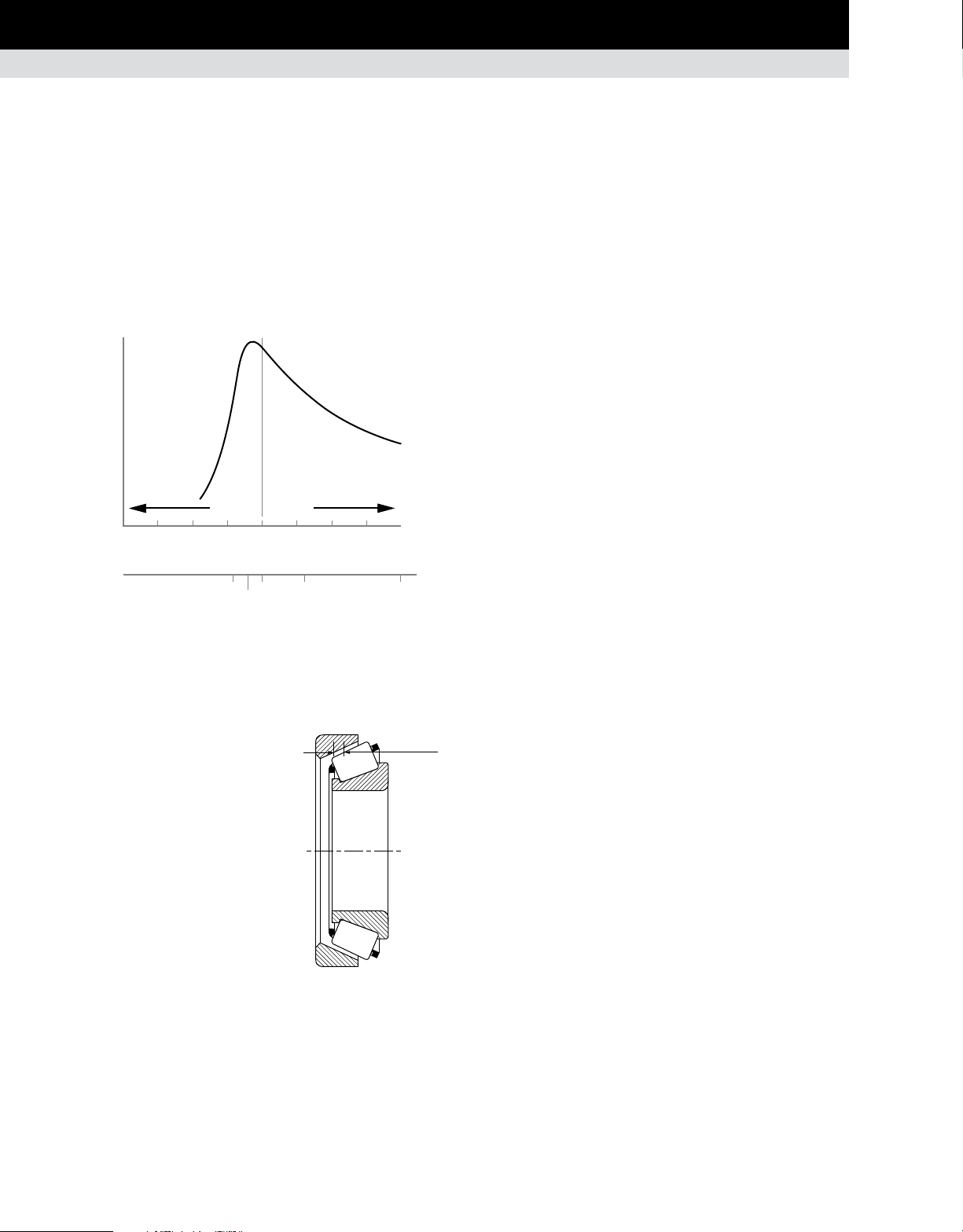
MOUNTING DESIGN, FITTING PRACTICE, SETTING AND INSTALLATION
TAPERED ROLLER BEARINGS
SETTING
Setting is defined as the axial clearance between roller and
raceway. Establishing the setting at the time of assembly is an
inherent advantage of tapered roller bearings. They can be set
to provide optimum performance in almost any application. Fig.
83 gives an example of the relationship between fatigue life
and bearing setting. Unlike some types of anti-friction bearings,
tapered roller bearings do not rely strictly on housing or shaft
fits to obtain a certain bearing setting. One ring can be moved
axially relative to the other to obtain the desired bearing setting.
100
Rated life (percent)
0
-0.15 -0.10 -0.05 0.000 0.05 0.10 0.15 mm
-0.006 -0.0040 -0.0020 0.00 0.0020 0.0040 0.0060 in
Fig. 83. Typical life vs. setting curve.
At assembly, the conditions of bearing setting are defined as:
Endplay (EP) – An axial clear-
•
ance between rollers and raceways
producing a measurable axial shaft
movement when a small axial force
is applied – first in one direction
then in the other, while oscillating
or rotating the shaft. See fig. 84.
Preload (PL) – An axial interference
•
between rollers and raceways such
that there is no measurable axial
shaft movement when a small
axial force is applied – in both
directions – while oscillating or
rotating the shaft.
Line-to-line – A zero setting
•
condition: the transitional point
between endplay and preload.
Preload Endplay
Axial clearance
360 180 135 100
216
Load zone (degrees)
Fig. 84. Internal
clearance – endplay.
Axial Endplay
Bearing setting obtained during initial assembly and adjustment
is the cold or ambient bearing setting, and is established before
the equipment is subjected to service.
Bearing setting during operation is known as the operating
bearing setting, and is a result of changes in the ambient bearing
setting due to thermal expansion and deflections encountered
during service.
The ambient bearing setting necessary to produce the optimum
operating bearing setting varies with the application. Application
experience or testing generally determines optimum settings.
Frequently, however, the exact relationship of ambient to
operating bearing setting is unknown and an educated estimate
has to be made. To determine a suggested ambient bearing setting
for a specific application, contact your Timken engineer.
Generally, the ideal operating bearing setting is near zero to
maximize bearing life (fig. 83). Most bearings are set with endplay
at assembly to reach the desired near-zero setting at operating
temperature.
There is an ideal bearing setting value for every application. To
achieve this condition, the bearing setting must take into account
deflection under load (radial + axial) as well as thermal expansions
and material used.
1. Standard mounting
Operating setting = mounted setting ± temperature effect +
deflection
2. Pre-set assemblies
Mounted EP or PL = bench EP or bench PL – effect of fits
Operating setting = mounted EP or PL (MEP or MPL) +
deflection ± temperature effect
The temperature and fit effects will depend upon the type of
mounting, bearing geometry and size, shaft and housing sizes,
and material as defined in the following sections. Dimensional
parameters affecting bearing setting are noted in fig. 85.
80 TIMKEN ENGINEERING MANUAL
Page 83

MOUNTING DESIGN, FITTING PRACTICE, SETTING AND INSTALLATION
L
TAPERED ROLLER BEARINGS
Fit effect
Solid shaft/heavy section housing
Setting Reduction/Width Increase for Single Inner Ring
= 0.5
0.39 d
Hollow shaft/thin-wall section
Shaft Reduction/Width Increase for Single Inner Ring
= 0.5
0.39 do
Shaft Reduction/Width Increase for Single Outer Ring
= 0.5
0.39 D
(1)
These equations apply only to ferrous shaft and housing.
(1)
K d
( )( )
Setting Reduction/Width Increase for Single Outer Ring
= 0.5
0.39 D
K D
( )( )
K d
( )( )
K D
( )( )
o
o
o
S
H
1 -
[
1 -
d
1 -
D
[
1 -
D
2
d
si
( )
d
2
d
si
( )
o
2
D
( )
H
2
D
o
( )
H
S
[
H
[
D
H
Fig. 85. Dimensional parameters affecting fit and
temperature effects on setting.
d
o
si
DoDd
d
Setting methods
Upper and lower limits of bearing setting values are determined
by consideration of the following factors:
Application type.
•
Duty cycle/loading.
•
Operational features of adjacent mechanical drive
•
elements.
Temperature effect
Direct mounting - setting change due to temperature
D
K
1
D
1
o1
o1
0.39 2 0.39 2
Indirect mounting - setting change due to temperature
0.39 2 0.39 2
1 2
Direct mounting
T
=
aTΔT
a
=
( )( )
[
K
ΔT
T
T
( )( )
[
L
Fig. 86. Direct and indirect mounting.
D
K
2
+
( )( )
+
( )( )
o2
D
K
2
o2
1 2
Indirect mounting
+ L
[
- L
[
Changes in bearing setting due to temperature differentials
•
and deflections.
Size of bearing and method of obtaining bearing setting.
•
Lubrication method.
•
Housing and shaft material.
•
The setting value to be applied during assembly will depend on
any changes that may occur during operation. In the absence of
experience with bearings of similar size and operating conditions,
a bearing setting range suggestion should be obtained from your
Timken engineer.
TIMKEN ENGINEERING MANUAL
81
Page 84

MOUNTING DESIGN, FITTING PRACTICE, SETTING AND INSTALLATION
SPHERICAL AND CYLINDRICAL ROLLER BEARINGS
SPHERICAL AND CYLINDRICAL ROLLER BEARINGS
MOUNTING
Spherical roller bearings can be mounted individually, but most
often are mounted in combination with another spherical roller
bearing or a cylindrical roller bearing.
With spherical roller bearings, typically one bearing is fixed axially
and the other is mounted with loose fits and axial space. This
allows movement or float for environmental conditions such as
uneven thermal growth between shaft and housing.
Cylindrical roller bearings can be mounted individually, but most
often are mounted in combination with another cylindrical roller,
a spherical roller or a tapered roller bearing.
Fig. 87 shows a typical gearbox application using two spherical
roller bearings where one bearing is free to float and the other
bearing is fixed axially.
Effective bearing
spread
Fig. 88 shows a pulverizer wheel assembly where a doublerow spherical roller bearing is mounted in combination with a
cylindrical roller bearing. In this application, the cylindrical roller
bearing allows the shaft to float relative to the housing.
Fig. 89 shows a single-reduction gear reducer with herringbone
gears. A tapered roller bearing is mounted in combination with a
cylindrical roller bearing on the upper shaft, and two cylindrical
roller bearings are mounted on the lower shaft.
FITTING PRACTICE
Tables 55 -67 on pages 120-131 list the recommended fitting
practices for spherical roller and cylindrical roller bearings. The
tables assume:
The bearing is of normal precision.
•
The housing is thick and made from steel or cast iron.
•
The shaft is solid and made from steel.
•
The bearing seats are ground or accurately turned to less
•
than approximately 1.6 µm Ra finish.
The suggested fit symbols are in accordance with ISO 286. For
help with recommended fitting practices, contact your Timken
engineer.
Float position Fixed position
Fig. 87. Spherical roller bearing direct mounting.
As a general guideline, rotating inner rings should be applied
with an interference fit. Loose fits may permit the inner rings to
creep or turn and wear the shaft and the backing shoulder. This
wear may result in excessive bearing looseness and possible
bearing and shaft damage. Additionally, abrasive metal particles
resulting from creep or turning may enter into the bearing and
cause damage and vibration.
Fig. 88. Pulverizer wheel assembly. Fig. 89. Single-reduction gear reducer.
TIMKEN ENGINEERING MANUAL
82
Page 85

MOUNTING DESIGN, FITTING PRACTICE, SETTING AND INSTALLATION
SPHERICAL AND CYLINDRICAL ROLLER BEARINGS
Stationary inner-ring fitting practice depends on the loading of the
application. The load conditions and bearing envelope dimensions
should be used to select the suggested shaft fit from the tables.
Similarly, rotating outer-ring applications should use an interference fit between the outer ring and housing.
Stationary outer rings are generally mounted with loose fits to
permit assembly and disassembly. The loose fit also permits
axial movement when a spherical bearing is mounted in the
float position.
Thin-walled housings, light-alloy housings or hollow shafts
must use press fits tighter than those required for thick-walled
housings, steel, or cast iron housings or solid shafts. Tighter fits
also are required when mounting the bearing on relatively rough
or unground surfaces.
Tapered bore designs
Typically, the tapered bore bearings are selected to simplify shaft
mounting and dismounting. Since the spherical roller bearing is
not separable, mounting can be simplified by use of an adapter
sleeve with a cylindrical bore and tapered O.D. A tapered bore
roller bearing also can be mounted directly onto a tapered shaft.
Fitting practice
An interference fit between the inner ring and a solid steel
•
shaft will reduce the radial clearance within the bearing by
approximately 80 percent of the fit.
Interference fits between the outer ring and steel or cast iron
•
housing will reduce radial clearance by approximately 60
percent.
Spherical roller bearings with a tapered bore require a
•
slightly greater interference fit on the shaft than a
cylindrical bore bearing.
NOTE
It is critical to select the RIC that allows for this reduction.
Thermal gradients
Thermal gradients within the bearing are primarily a func-
•
tion of the bearing rotational speed. As speed increases,
thermal gradients increase, thermal growth occurs and the
radial clearance is reduced.
As a rule of thumb, radial clearance should be increased for
•
speeds in excess of 70 percent of the speed rating.
For help selecting the correct radial internal clearance for your
application, consult with your Timken engineer.
Fig. 90. Spherical roller
bearing mounted with
an adapter sleeve.
Bearings with a tapered bore typically require a tighter fit on the
shaft than bearings with a cylindrical bore. A locknut is typically
used to drive the inner ring up a tapered shaft sleeve. The locknut
position is then secured by use of a lockwasher or lockplate.
Timken offers a wide range of accessories to ease the assembly
of spherical roller bearings with a tapered bore (see page 89).
For approximating the clearance loss for axial drive-up, an 85
percent radial loss approximation can be used. That is, the radial
clearance loss per axial drive-up can roughly be approximated as
71 μm/mm for a 1:12 tapered bore and 28 μm/mm for a 1:30 tapered
bore. Table 41 on page 85 shows the relationship between axial
displacement of the inner ring and the reduction in RIC (radial
internal clearance) for tapered bore applications.
SETTING
To achieve appropriate operation clearance, attention must be
paid to the effects fitting practice and thermal gradients have
within the bearing.
Radial internal clearance tolerances are listed in tables 40 and 41
for spherical and cylindrical roller bearings, respectively.
Spherical and cylindrical roller bearings are ordered with a
specified standard or non-standard radial internal clearance
value. The standard radial internal clearances are designated
as C2, C0 (normal), C3, C4 or C5 and are in accordance with ISO
5753. C2 represents the minimum clearance and C5 represents the
maximum clearance. Non-standardized values also are available
by special request.
The clearance required for a given application depends on the
desired operating precision, the rotational speed of the bearing,
and the fitting practice used. Most applications use a normal or
C3 clearance. Typically, larger clearance reduces the operating
load zone of the bearing, increases the maximum roller load,
and reduces the bearing’s expected life. However, a spherical
or cylindrical roller bearing that has been put into a preload
condition can experience premature bearing damage caused by
excessive heat generation and/or material fatigue. As a general
guideline, spherical and cylindrical roller bearings should not
operate in a preloaded condition.
TIMKEN ENGINEERING MANUAL
83
Page 86

MOUNTING DESIGN, FITTING PRACTICE, SETTING AND INSTALLATION
MOUNTING DESIGN, FITTING PRACTICE, SETTING AND INSTALLATION
TAPERED ROLLER BEARINGS
SPHERICAL AND CYLINDRICAL ROLLER BEARINGS
TABLE 40. RADIAL INTERNAL CLEARANCE LIMITS – SPHERICAL ROLLER BEARINGS – CYLINDRICAL BORE
Radial Internal Clearance Prior To Mounting
Bore
(Nominal)
C2 C3 C5
Over Incl. Min. Max. Min. Max. Min. Max.
mm
in.
20 30 0.015 0.025 0.040 0.055 0.075 0.095
0.9449 1.1811 0.0006 0.0010 0.0016 0.0022 0.0030 0.0037
30 40 0.015 0.030 0.045 0.060 0.080 0.100
1.1811 1.5748 0.0006 0.0012 0.0018 0.0024 0.0031 0.0039
40 50 0.020 0.035 0.055 0.075 0.100 0.125
1.5748 1.9685 0.0008 0.0014 0.0022 0.0030 0.0039 0.0049
50 65 0.020 0.040 0.065 0.090 0.120 0.150
1.9685 2.5591 0.0008 0.0016 0.0026 0.0035 0.0047 0.0059
65 80 0.030 0.050 0.080 0.110 0.145 0.180
2.5591 3.1496 0.0012 0.0020 0.0031 0.0043 0.0057 0.0071
80 100 0.035 0.060 0.100 0.135 0.180 0.225
3.1496 3.9370 0.0014 0.0024 0.0039 0.0053 0.0071 0.0089
100 120 0.040 0.075 0.120 0.160 0.210 0.260
3.9370 4.7244 0.0016 0.0030 0.0047 0.0063 0.0083 0.0102
120 140 0.050 0.095 0.145 0.190 0.240 0.300
4.7244 5.5118 0.0020 0.0037 0.0057 0.0075 0.0094 0.0118
140 160 0.060 0.110 0.170 0.220 0.280 0.350
5.5118 6.2992 0.0024 0.0043 0.0067 0.0087 0.0110 0.0138
160 180 0.065 0.120 0.180 0.240 0.310 0.390
6.2992 7.0866 0.0026 0.0047 0.0071 0.0094 0.0122 0.0154
180 200 0.070 0.130 0.200 0.260 0.340 0.430
7.0866 7.8740 0.0028 0.0051 0.0079 0.0102 0.0134 0.0169
200 225 0.080 0.140 0.220 0.290 0.380 0.470
7.8740 8.8582 0.0031 0.0055 0.0087 0.0114 0.0150 0.0185
225 250 0.090 0.150 0.240 0.320 0.420 0.520
8.8582 9.8425 0.0035 0.0059 0.0094 0.0126 0.0165 0.0205
250 280 0.100 0.170 0.260 0.350 0.460 0.570
9.8425 11.0236 0.0039 0.0067 0.0102 0.0138 0.0181 0.0224
280 315 0.110 0.190 0.280 0.370 0.500 0.630
11.0236 12.4016 0.0043 0.0075 0.0110 0.0146 0.0197 0.0248
315 355 0.120 0.200 0.310 0.410 0.550 0.690
12.4016 13.9764 0.0047 0.0079 0.0122 0.0161 0.0217 0.0272
355 400 0.130 0.220 0.340 0.450 0.600 0.750
13.9764 15.7480 0.0051 0.0087 0.0134 0.0177 0.0236 0.0295
400 450 0.140 0.240 0.370 0.500 0.660 0.820
15.7480 17.7165 0.0055 0.0094 0.0146 0.0197 0.026 0.0323
450 500 0.140 0.260 0.410 0.550 0.720 0.900
17.7165 19.6850 0.0055 0.0102 0.0161 0.0217 0.0283 0.0354
500 560 0.150 0.280 0.440 0.600 0.780 1.000
19.6850 22.0472 0.0059 0.0110 0.0173 0.0236 0.0307 0.0394
560 630 0.170 0.310 0.480 0.650 0.850 1.100
22.0472 24.8031 0.0067 0.0122 0.0189 0.0256 0.0335 0.0433
mm
in.
mm
in.
Normal
CO
Min. Max. Min. Max.
mm
in.
mm
in.
mm
in.
C4
mm
in.
mm
in.
84 TIMKEN ENGINEERING MANUAL
TIMKEN ENGINEERING MANUAL
84
Page 87

MOUNTING DESIGN, FITTING PRACTICE, SETTING AND INSTALLATION
SPHERICAL AND CYLINDRICAL ROLLER BEARINGS
Continued from previous page.
Over Incl. Min. Max. Min. Max. Min. Max.
mm
630 710 0.190 0.350 0.530 0.700 0.920 1.190
24.8031 27.9528 0.0075 0.0138 0.0209 0.0276 0.0362 0.0469
710 800 0.210 0.390 0.580 0.770 1.010 1.300
27.9528 31.4961 0.0083 0.0154 0.0228 0.0303 0.0398 0.0512
800 900 0.230 0.430 0.650 0.860 1.120 1.440
31.4961 35.4331 0.0091 0.0169 0.0256 0.0339 0.0441 0.0567
900 1000 0.260 0.480 0.710 0.930 1.220 1.570
35.4331 39.3701 0.0102 0.0189 0.0280 0.0366 0.0480 0.0618
1000 1120 0.290 0.530 0.780 1.020 1.330 1.720
39.3701 44.0950 0.0114 0.0209 0.0307 0.0402 0.0524 0.0677
1120 1250 0.320 0.580 0.860 1.120 1.460 1.870
44.0950 49.2130 0.0126 0.0228 0.0339 0.0441 0.0575 0.0736
TABLE 40. RADIAL INTERNAL CLEARANCE LIMITS – SPHERICAL ROLLER BEARINGS – CYLINDRICAL BORE
Radial Internal Clearance Prior To Mounting
in.
Bore
(Nominal)
mm
in.
mm
in.
Normal
CO
Min. Max. Min. Max.
C2 C3 C5
mm
in.
mm
in.
mm
in.
C4
mm
in.
TABLE 41. SPHERICAL ROLLER BEARING ENDPLAY
E.P
––––
RIC
8.7
7.0
5.5
5.0
4.8
4.4
4.3
4.2
3.9
Spherical roller bearings
Series
39
30
22
31
40
32
23
41
33
mm
in.
TIMKEN ENGINEERING MANUAL
85
Page 88

MOUNTING DESIGN, FITTING PRACTICE, SETTING AND INSTALLATION
SPHERICAL AND CYLINDRICAL ROLLER BEARINGS
TABLE 42. RADIAL INTERNAL CLEARANCE LIMITS – SPHERICAL ROLLER BEARINGS – TAPERED BORE
Radial Internal Clearance Prior To Mounting
Bore
(Nominal)
Over Incl. Min. Max. Min. Max. Min. Max. Min. Max. Min. Max. Min. Max. CO C3 C4
mm
mm
in.
20 30 0.020 0.030 0.040 0.055 0.075 0.095 0.015 0.020 0.230 0.300 – – 0.015 0.025 0.040
0.9449 1.1811 0.0008 0.0012 0.0016 0.0022 0.0030 0.0037 0.0006 0.0008 0.0091 0.0118 – – 0.0006 0.0010 0.0016
30 40 0.025 0.035 0.050 0.065 0.085 0.105 0.020 0.025 0.300 0.380 – – 0.015 0.025 0.040
1.1811 1.5748 0.0010 0.0014 0.0020 0.0026 0.0033 0.0041 0.0008 0.0010 0.0118 0.0150 – – 0.0006 0.0010 0.0016
40 50 0.030 0.045 0.060 0.080 0.100 0.130 0.025 0.030 0.380 0.460 – – 0.02 0.030 0.050
1.5748 1.9685 0.0012 0.0018 0.0024 0.0031 0.0039 0.0051 0.0010 0.0012 0.0150 0.0181 – – 0.0008 0.0012 0.0020
50 65 0.040 0.055 0.075 0.095 0.120 0.160 0.030 0.038 0.460 0.560 – – 0.025 0.040 0.060
1.9685 2.5591 0.0016 0.0022 0.0030 0.0037 0.0047 0.0063 0.0012 0.0015 0.0181 0.0220 – – 0.0010 0.0015 0.0025
65 80 0.050 0.070 0.0950 0.120 0.150 0.200 0.038 0.051 0.560 0.760 – – 0.025 0.045 0.075
2.5591 3.1496 0.0020 0.0028 0.0037 0.0047 0.0059 0.0079 0.0015 0.0020 0.0220 0.0299 – – 0.0010 0.0017 0.0030
80 100 0.055 0.080 0.110 0.140 0.180 0.230 0.046 0.064 0.680 0.970 – – 0.036 0.050 0.075
3.1496 3.9370 0.0022 0.0030 0.0043 0.0055 0.0071 0.0091 0.0018 0.0025 0.0268 0.0382 – – 0.0014 0.0020 0.0030
100 120 0.065 0.100 0.135 0.170 0.220 0.280 0.051 0.071 0.760 1.070 1.900 2.540 0.051 0.060 0.100
3.9370 4.7244 0.0026 0.0039 0.0053 0.0067 0.0087 0.0110 0.0020 0.0028 0.0299 0.0421 0.0748 0.1000 0.0020 0.0025 0.0040
120 140 0.080 0.120 0.160 0.200 0.260 0.330 0.064 0.089 0.890 1.270 2.290 3.050 0.056 0.075 0.115
4.7244 5.5118 0.0031 0.0047 0.0063 0.0079 0.0102 0.0130 0.0025 0.0035 0.0350 0.0500 0.0902 0.1201 0.0022 0.0030 0.0045
140 160 0.090 0.130 0.180 0.230 0.300 0.380 0.076 0.102 1.140 1.520 2.670 3.430 0.056 0.075 0.125
5.5118 6.2992 0.0035 0.0051 0.0071 0.0091 0.0118 0.0150 0.0030 0.0040 0.0449 0.0598 0.1051 0.1350 0.0022 0.0030 0.0050
160 180 0.100 0.140
6.2992 7.0866 0.0039 0.0055 0.0079 0.0102 0.0134 0.0169 0.0030 0.0045 0.0449 0.0650 0.1051 0.1598 0.0024 0.0035 0.0060
180 200 0.110 0.160 0.220 0.290 0.370 0.470 0.089 0.127 1.400 1.900 3.050 4.450 0.071 0.100 0.165
7.0866 7.8740 0.0043 0.0063 0.0087 0.0114 0.0146 0.0185 0.0035 0.0050 0.0551 0.0748 0.1201 0.1752 0.0028 0.0040 0.0065
200 225 0.120 0.180 0.250 0.320 0.410 0.520 0.102 0.140 1.520 2.030 3.560 4.830 0.076 0.115 0.180
7.8740 8.8582 0.0047 0.0071 0.0098 0.0126 0.0161 0.0205 0.0040 0.0055 0.0598 0.0799 0.1402 0.1902 0.0030 0.0045 0.0070
225 250 0.140 0.200 0.270 0.350 0.450 0.570 0.114 0.152 1.780 2.290 4.060 5.330 0.089 0.115 0.200
8.8582 9.8425 0.0055 0.0079 0.0106 0.0138 0.0177 0.0224 0.0045 0.0060 0.0701 0.0902 0.1598 0.2098 0.0035 0.0045 0.0080
250 280 0.150 0.220 0.300 0.390 0.490 0.620 0.114 0.165 1.780 2.540 4.060 5.840 0.102 0.140 0.230
9.8425 11.0236 0.0059 0.0087 0.0118 0.0154 0.0193 0.0244 0.0045 0.0065 0.0701 0.1000 0.1598 0.2299 0.0040 0.0055 0.0090
280 315 0.170 0.240 0.330 0.430 0.540 0.680 0.127 0.178 1.900 2.670 4.450 6.220 0.102 0.150 0.250
11.0236 12.4016 0.0067 0.0094 0.0130 0.0169 0.0213 0.0268 0.0050 0.0070 0.0748 0.1051 0.1752 0.2449 0.0040 0.0060 0.0100
315 355 0.190 0.270 0.360 0.470 0.590 0.740 0.140 0.190 2.030 2.790 4.830 6.600 0.114 0.165 0.280
12.4016 13.9764 0.0075 0.0106 0.0142 0.0185 0.0232 0.0291 0.0055 0.0075 0.0799 0.1098 0.1902 0.2598 0.0045 0.0065 0.0110
355 400 0.210 0.300 0.400 0.520 0.650 0.820 0.152 0.203 2.290 3.050 5.330 7.110 0.127 0.190 0.330
13.9764 15.7480 0.0083 0.0118 0.0157 0.0205 0.0256 0.0323 0.0060 0.0080 0.0902 0.1201 0.2098 0.2799 0.0050 0.0075 0.0130
mm
in.
in.
Normal
CO
Min. Max. Min. Max.
C2 C3 C5 1:12 Taper 1:30 Taper
mm
mm
in.
in.
0.200 0.260 0.340 0.430 0.076 0.114 1.140 1.650 2.670 4.060 0.061 0.090 0.150
mm
in.
C4
mm
mm
in.
in.
Suggested
Reduction
of RIC
Due to
Installation
mm
in.
mm
in.
Axial Displacement
of Inner Ring for
RIC Reduction –
Tapered Shaft
mm
mm
in.
in.
mm
in.
(1)(2)
mm
in.
Minimum Permissible
RIC After
Installation
mm
in.
(1)
mm
in.
mm
in.
TIMKEN ENGINEERING MANUAL
86
Page 89

MOUNTING DESIGN, FITTING PRACTICE, SETTING AND INSTALLATION
SPHERICAL AND CYLINDRICAL ROLLER BEARINGS
Continued from previous page.
Bore
(Nominal)
Over Incl. Min. Max. Min. Max. Min. Max. Min. Max. Min. Max. Min. Max. CO C3 C4
mm
in.
400 450 0.230 0.330 0.440 0.570 0.720 0.910 0.165 0.216 2.540 3.300 5.840 7.620 0.152 0.230 0.360
15.7480 17.7165 0.0091 0.0130 0.0173 0.0224 0.0283 0.0358 0.0065 0.0085 0.1000 0.1299 0.2299 0.3000 0.0060 0.0090 0.0140
450 500 0.260 0.370 0.490 0.630 0.790 1.000 0.178 0.229 2.670 3.430 6.220 8.000 0.165 0.270 0.410
17.7165 19.6850 0.0102 0.0146 0.0193 0.0248 0.0311 0.0394 0.0070 0.0090 0.1051 0.1350 0.2449 0.3150 0.0065 0.0105 0.0160
500 560 0.290 0.410 0.540 0.680 0.870 1.100 0.203 0.254 3.050 3.810 7.110 8.890 0.178 0.290 0.440
19.6850 22.0472 0.0114 0.0161 0.0213 0.0268 0.0343 0.0433 0.0080 0.0100 0.1201 0.1500 0.2799 0.3500 0.0070 0.0115 0.0175
560 630 0.320 0.460 0.600 0.760 0.980 1.230 0.229 0.279 3.430 4.190 8.000 9.780 0.203 0.320 0.510
22.0472 24.8031 0.0126 0.0181 0.0236 0.0299 0.0386 0.0484 0.0090 0.0110 0.1350 0.1650 0.3150 0.3850 0.0080 0.0125 0.0200
630 710 0.350 0.510 0.670 0.850 1.090 1.360 0.254 0.305 3.810 4.570 8.890 10.670 0.203 0.370 0.550
24.8031 27.9528 0.0138 0.0201 0.0264 0.0335 0.0429 0.0535 0.0100 0.0120 0.1500 0.1799 0.3500 0.4201 0.0080 0.0145 0.0215
710 800 0.390 0.570 0.750 0.960 1.220 1.500 0.279 0.356 4.190 5.330 9.780 12.450 0.229 0.390 0.610
27.9528 31.4961 0.0154 0.0224 0.0295 0.0378 0.0480 0.0591 0.0110 0.0140 0.1650 0.2098 0.3850 0.4902 0.0090 0.0155 0.0240
800 900 0.440 0.640 0.840 1.070 1.370 1.690 0.305 0.381 4.570 5.720 10.670 13.330 0.252 0.460 0.690
31.4961 35.4331 0.0173 0.0252 0.0331 0.0421 0.0539 0.0665 0.0120 0.0150 0.1799 0.2252 0.4201 0.5248 0.0100 0.0180 0.0270
900 1000 0.490 0.710 0.930 1.190 1.520 1.860 0.356 0.432 5.330 6.480 12.450 15.110 0.279 0.490 0.750
35.4331 39.3701 0.0193 0.0280 0.0366 0.0469 0.0598 0.0732 0.0140 0.0170 0.2100 0.2551 0.4902 0.5949 0.0110 0.0195 0.0300
1000 1120 0.530 0.770 1.030 1.300 1.670 2.050 0.400 0.480 6.100 7.240 14.220 16.890 0.280 0.550 0.810
39.3701 44.0950 0.0209 0.0303 0.0406 0.0512 0.0657 0.0807 0.0160 0.0190 0.2400 0.2850 0.5600 0.6650 0.0110 0.0215 0.0320
1120 1250 0.570 0.830
44.0950 49.2130 0.0224 0.0327 0.0441 0.0559 0.0720 0.0886 0.0170 0.0200 0.2550 0.3000 0.5950 0.7000 0.0130 0.0240 0.0360
Note: Axial displacement values apply to solid steel shafts or hollow shafts with bore diameter less than half the shaft diameter. For shaft materials other than steel, or for
thin-walled shafts, please consult your Timken sales engineer.
(1)
This displacement is valid for assembly of tapered bore bearings and is measured starting from a line-to-line fit of the bearing bore to the tapered shaft.
(2)
1:12 Taper used for 213, 222, 223, 230, 231, 232, 233, 238, 239 series. 1:30 Taper used for 240, 241, 242 series. For sleeve mounting, multiply axial displacement values by 1.1 for 1:12
Taper or by 1.05 for 1:30 Taper. For questions on tapered shaft data, consult your Timken sales engineer.
TABLE 5. RADIAL INTERNAL CLEARANCE LIMITS – SPHERICAL ROLLER BEARINGS – TAPERED BORE
mm
in.
Radial Internal Clearance Prior To Mounting
Normal
CO
Min. Max. Min. Max.
C2 C3 C5 1:12 Taper 1:30 Taper
mm
mm
in.
mm
in.
in.
1.120 1.420 1.830 2.250 0.430 0.500 6.480 7.620 15.110 17.780 0.330 0.610 0.910
mm
in.
C4
mm
mm
in.
in.
Suggested
Reduction
of RIC
Due to
Installation
mm
in.
mm
in.
Axial Displacement
of Inner Ring for
RIC Reduction –
Tapered Shaft
mm
mm
in.
in.
mm
in.
(1)(2)
mm
in.
Minimum Permissible
RIC After
Installation
mm
in.
(1)
mm
in.
mm
in.
TIMKEN ENGINEERING MANUAL
87
Page 90

MOUNTING DESIGN, FITTING PRACTICE, SETTING AND INSTALLATION
SPHERICAL AND CYLINDRICAL ROLLER BEARINGS
TABLE 43. RADIAL INTERNAL CLEARANCE LIMITS – CYLINDRICAL ROLLER BEARINGS – CYLINDRICAL BORE
Bore – RIC
Bore (Nominal) C2 C0 C3 C4 C5
Over Incl. Min. Max. Min. Max. Min. Max. Min. Max. Min. Max.
mm
in.
– 10 0.000 0.025 0.020 0.0045 0.035 0.060 0.050 0.075 – –
– 0.3937 0.0000 0.0010 0.0008 0.0018 0.0014 0.0024 0.0020 0.0030 – –
10 24 0.000 0.025 0.020 0.0045 0.035 0.060 0.050 0.075 0.065 0.090
0.3937 0.9449 0.0000 0.0010 0.0008 0.0018 0.0014 0.0024 0.0020 0.0030 0.0026 0.0035
24 30 0.000 0.025 0.020 0.0045 0.035 0.060 0.050 0.075 0.070 0.095
0.9449 1.1811 0.0000 0.0010 0.0008 0.0018 0.0014 0.0024 0.0020 0.0030 0.0028 0.0037
30 40 0.005 0.030 0.025 0.050 0.0045 0.070 0.060 0.085 0.080 0.105
1.1811 1.5748 0.0002 0.0012 0.0010 0.0020 0.0018 0.0028 0.0024 0.0033 0.0031 0.0041
40 50 0.005 0.035 0.030 0.060 0.050 0.080 0.070 0.100 0.095 0.125
1.5748 1.9685 0.0002 0.0014 0.0012 0.0024 0.0020 0.0031 0.0028 0.0039 0.0037 0.0049
50 65 0.010 0.040 0.040 0.070 0.060 0.090 0.080 0.110 0.110 0.140
1.9685 2.5591 0.0004 0.0016 0.0016 0.0028 0.0024 0.0035 0.0031 0.0043 0.0043 0.0055
65 80 0.010 0.0045 0.040 0.075 0.065 0.100 0.090 0.125 0.130 0.165
2.5591 3.1496 0.0004 0.0018 0.0016 0.0030 0.0026 0.0039 0.0035 0.0049 0.0051 0.0065
80 100 0.015 0.050 0.050 0.085 0.075 0.110 0.105 0.140 0.155 0.190
3.1496 3.9370 0.0006 0.0020 0.0020 0.0033 0.0030 0.0043 0.0041 0.0055 0.0061 0.0075
100 120 0.015 0.055 0.050 0.090 0.085 0.125 0.125 0.165 0.180 0.220
3.9370 4.7244 0.0006 0.0022 0.0020 0.0035 0.0033 0.0049 0.0049 0.0065 0.0071 0.0087
120 140 0.015 0.060 0.060 0.105 0.100 0.145 0.145 0.190 0.200 0.245
4.7244 5.5118 0.0006 0.0024 0.0024 0.0041 0.0039 0.0057 0.0057 0.0075 0.0079 0.0096
140 160 0.020 0.070 0.070 0.120 0.115 0.165 0.165 0.215 0.225 0.275
5.5118 6.2992 0.0008 0.0028 0.0028 0.0047 0.0045 0.0065 0.0065 0.0085 0.0089 0.0108
160 180 0.025 0.075 0.075 0.125 0.120 0.170 0.170 0.220 0.250 0.300
6.2992 7.0866 0.0010 0.0030 0.0030 0.0049 0.0047 0.0067 0.0067 0.0087 0.0098 0.0118
180 200 0.035 0.090 0.090 0.145 0.140 0.195 0.195 0.250 0.275 0.330
7.0866 7.8740 0.0014 0.0035 0.0035 0.0057 0.0055 0.0077 0.0077 0.0098 0.0108 0.0130
200 225 0.045 0.105 0.105 0.165 0.160 0.220 0.220 0.280 0.305 0.365
7.8740 8.8583 0.0018 0.0041 0.0041 0.0065 0.0063 0.0087 0.0087 0.0110 0.0120 0.0144
225 250 0.045 0.110 0.110 0.175 0.170 0.235 0.235 0.300 0.330 0.395
8.8583 9.8425 0.0018 0.0043 0.0043 0.0069 0.0067 0.0093
250 280 0.055 0.125 0.125 0.195 0.190 0.260 0.260 0.330 0.370 0.440
9.8425 11.0236 0.0022 0.0049 0.0049 0.0077 0.0075 0.0102 0.0102 0.0130 0.0146 0.0173
280 315 0.055 0.130 0.130 0.205 0.200 0.275 0.275 0.350 0.410 0.485
11.0236 12.4016 0.0022 0.0051 0.0051 0.0081 0.0079 0.0108 0.0108 0.0138 0.0161 0.0191
315 355 0.065 0.145 0.145 0.225 0.225 0.305 0.305 0.385 0.455 0.535
12.4016 13.9764 0.0026 0.0057 0.0057 0.0089 0.0089 0.0120 0.0120 0.0152 0.0179 0.0211
355 400 0.100 0.190 0.190 0.280 0.280 0.370 0.370 0.460 0.510 0.600
13.9764 15.7480 0.0039 0.0075 0.0075 0.0110 0.0110 0.0146 0.0146 0.0181 0.0201 0.0236
400 450 0.110 0.210 0.210 0.310 0.310 0.410 0.410 0.510 0.565 0.665
15.7480 17.7165 0.0043 0.0083 0.0083 0.0122 0.0122 0.0161 0.0161 0.0201 0.0222 0.0262
450 500 0.110 0.220 0.220 0.330 0.330 0.440 0.440 0.550 0.625 0.735
17.7165 19.6850 0.0043 0.0087 0.0087 0.0130 0.0130 0.0173 0.0173 0.0217 0.0246 0.0289
500 560 0.120 0.240 0.240 0.360 0.360 0.480 0.480 0.600 0.690 0.810
19.6850 22.0472 0.0047 0.0095 0.0095 0.0142 0.0142 0.0189 0.0189 0.0236 0.0272 0.0319
560 630 0.140 0.260 0.260 0.380 0.380 0.500 0.500 0.620 0.780 0.900
22.0472 24.8031 0.0055 0.0102 0.0102 0.0150 0.0150 0.0197 0.0197 0.0244 0.0307 0.0354
630 710 0.145 0.285 0.285 0.425 0.425 0.565 0.565 0.705 0.865 1.005
24.8031 27.9528 0.0057 0.0112 0.0112 0.0167 0.0167 0.0222 0.0222 0.0278 0.0341 0.0396
710 800 0.150 0.310 0.310 0.470 0.470 0.630 0.630 0.790 0.975 1.135
27.9528 31.4961 0.0059 0.0122 0.0122 0.0185 0.0185 0.0248 0.0248 0.0311 0.0384 0.0447
800 900 0.180 0.350 0.350 0.520 0.520 0.690 0.690 0.860 1.095 1.265
31.4961 35.4331 0.0071 0.0138 0.0138 0.0205 0.0205 0.0272 0.0272 0.0339 0.0431 0.0498
900 1000 0.200 0.390 0.390 0.580 0.580 0.770 0.770 0.960 1.215 1.405
35.4331 39.3701 0.0079 0.0154 0.0154 0.0228 0.0228 0.0303 0.0303 0.0378 0.0478 0.0553
mm
in.
mm
in.
mm
in.
mm
in.
mm
in.
mm
in.
mm
in.
mm
in.
0.0093 0.0118 0.0130 0.0156
mm
in.
mm
in.
mm
in.
TIMKEN ENGINEERING MANUAL
88
Page 91

MOUNTING DESIGN, FITTING PRACTICE, SETTING AND INSTALLATION
SPHERICAL AND CYLINDRICAL ROLLER BEARINGS
EXAMPLE #1 –
Calculating RIC Reduction Using a Spherical Roller Bearing with Tapered Bore
Step 1:
Place bearing in upright position and center the inner ring and
rollers. Apply pressure to the inner ring and oscillate several
times to properly seat the rollers.
Step 2:
Use a feeler gauge to measure the unmounted radial internal
clearance (RIC) for both bearing rows.
- RIC must be checked at the unloaded roller.
- Feeler gauge must cover the length of the roller.
- Unmounted RIC is the thickest gauge that will slide through
the gap between the roller and outer ring.
- Unmounted RIC is then the
average reading for the
two rows.
Fig. 91. Measure RIC
before installation.
Example: 22328KEJW33C3 140 mm bore (5.5118 in.)
RIC measurement is 0.178 mm (0.0070 in.)
Step 3:
Use table 42 (page 86) to confirm that the measured unmounted
RIC value is within specification.
Example: 22328KEJW33C3 140 mm bore (5.5118 in.)
RIC range is 0.160 mm – 0.200 mm (0.0063 in. – 0.0079 in.), the
example’s measured RIC is 0.178 mm (0.007 in.) so it is within
specified range.
Step 4:
Use table 42 (page 86) to determine the Suggested Reduction
of RIC Due to Installation.
Example: 22328KEJW33C3 140 mm bore (5.5118 in.)
Suggested Reduction of RIC Due to installation is
0.064 mm – 0.089 mm (0.0025 in. – 0.0035 in.).
Step 5:
Determine the maximum and minimum RIC after mounting.
MAX RIC = actual unmounted RIC – maximum suggested
reduction in RIC
MIN RIC = actual unmounted RIC – maximum suggested
reduction in RIC
Example: 22328KEJW33C3 140 mm bore (5.5118 in.)
Max Mounted RIC: 0.178 mm – 0.064 mm = 0.114 mm
(0.0070 in. – 0.0025 in. = 0.0045 in.)
Min Mounted RIC: 0.178 mm – 0.089 mm = 0.089 mm
(0.0070 in. – 0.0035 in. = 0.0035 in.)
Step 6:
Use table 42 (page 86) to determine Axial Displacement of
Inner Ring for RIC Reduction.
Example: 22328KEJW33C3 140 mm bore (5.5118 in.)
22328KEJW33C3 is a 223 series which has a 1:12
tapered bore.
Axial Displacement of Inner Ring for RIC Reduction is
0.890 mm – 1.270 mm (0.035 in. – 0.050 in.).
Step 7:
Place bearing on tapered shaft (or tapered sleeve) until line-toline contact exists with the bearing bore.
Fig. 92. During mounting, the
RIC should be checked at
the unloaded roller.
Step 8:
Use a locknut (or hydraulic nut) to apply installation force
and move the bearing up the shaft or tapered sleeve until the
mounted RIC reaches the desired range established in Step 5.
During mounting, RIC should be measured at unloaded roller.
Example: 22328KEJW33C3 140 mm bore (5.5118 in.)
Mounted RIC range is 0.089 mm – 0.114 mm
(0.0035 in. – 0.0045 in.).
Step 9:
Use table 42 (page 86) to evaluate mounted RIC against
Minimum Permissible RIC After Installation.
Example: 22328KEJW33C3 140 mm bore (5.5118 in.)
The minimum permissible RIC after mounting would be
0.075 mm (0.0030 in.).
Step 7 (Alternative Procedure):
Use a locknut (or hydraulic nut) to apply installation force and
move the bearing up the shaft or tapered sleeve until the axial
displacement of the inner ring reaches the desired range.
During mounting, the axial displacement of the inner ring
should be measured.
Example: 22328KEJW33C3 140 mm bore (5.5118 in.)
Axial Displacement of Inner Ring for RIC Reduction is
0.890 mm – 1.270 mm (0.035 in. – 0.050 in.).
TIMKEN ENGINEERING MANUAL
89
Page 92

MOUNTING DESIGN, FITTING PRACTICE, SETTING AND INSTALLATION
MOUNTING DESIGN, FITTING PRACTICE, SETTING AND INSTALLATION
TAPERED ROLLER BEARINGS
SPHERICAL AND CYLINDRICAL ROLLER BEARINGS
EXAMPLE #2 –
Calculating RIC Reduction Using a Spherical Roller Bearing with Cylindrical Bore
Step 1:
Gather general information required for fitting practice review.
- Bearing Bore and OD Dimensions/Tolerances
- Bearing operating conditions (Load/Speed)
Calculate bearing loading to bearing rating ratio by dividing the
expected radial load by the basic dynamic radial load rating
(BDLR) of the bearing.
Example: 22230EMW33
- Bore: 149.975 mm -150.00 mm (5.9045 in. – 5.9055 in.)
- OD: 269.965 mm – 270.00 mm (10.6285 in. – 10.6299 in.)
- BDLR: 1000 KN (225,000 lbf)
- Speed: 1,200 RPM; rotating shaft
- Radial Loading: 90 KN (20,250 lbf)
- Lubrication: grease
- Load/Bearing Rating Ratio:
90 KN/1000 KN (20,250 lbf/225,000 lbf) = 0.09
P= 0.09
Step 2:
Determine which shaft and housing fits should be used.
- Using table 56 (page 126) determine the suggested fits for
the inner ring on the shaft.
- Using table 57 (page 127) determine the suggested fits for
the outer ring in the housing.
Example: 22230EMW33
Inner Ring/Shaft: 150 mm (5.9055 in.)
- Rotating inner ring
- Normal/light loads applied
- ISO fit – p6 suggested
Outer Ring: 270 mm OD (10.6299 in.)
- Solid, one piece housing
- Normal/light loads applied
- ISO fit – H8 suggested
Step 3:
Determine the shaft OD and housing bore
dimensions/tolerances.
- Using tables 68 and 69 (pages 132-137) determine the
suggested shaft diameter dimensions
- Using table 70 and 71 (pages 138-145) determine the suggested
housing bore dimension
Example: 22230EMW33
Shaft dimensions: p6 fit selected
Shaft tolerance: +0.043 mm/+0.068 mm
(+0.0017 in./+0.0027 in.)
Shaft diameter: 150.043 mm – 150.068 mm
(5.9072 in. – 5.9082 in.)
Housing Dimensions: H8 fit selected
Housing tolerance: +0.000 mm/+0.081 mm
(+0.0000 in./+0.0032 in.)
Housing diameter: 270.000 mm – 270.081 mm
(10.6299 in. – 10.6331 in.)
Step 4:
Calculate the resultant fits on the shaft and in the housing.
- Calculate the maximum and minimum interference fit
on the shaft.
- Calculate the maximum and minimum interference fit
in the housing.
- Note: Negative resultant fits are tight fit interference.
- Note: Positive resultant fits are loose fit interferences.
Example: 22230EMW33
Shaft Fit:
Max interference = min bore – max shaft OD 149.975 mm –
150.068 mm = -0.093 mm (tight fit) OR
5.9045 in. – 5.9082 in. = -0.0037 in. (tight fit)
Min interference = max bore – min shaft OD 150.000 mm –
150.043 mm = -0.043 mm (tight fit) OR
5.9055 in. – 5.9072 in. = -0.0017 in. (tight fit)
Housing Fit:
Max interference = min housing bore – max bearing OD
270.000 mm – 270.000 mm = 0.000 mm (loose) OR
10.6299 in. – 10.6299 in. = 0.0000 in. (loose)
Min interference = max housing bore – min bearing OD
270.081 mm – 269.965 mm = +0.116 mm (loose) OR
10.6331 in. – 10.6285 in. = +0.0046 in. (loose)
90 TIMKEN ENGINEERING MANUAL
Page 93

MOUNTING DESIGN, FITTING PRACTICE, SETTING AND INSTALLATION
SPHERICAL AND CYLINDRICAL ROLLER BEARINGS
Step 5:
Calculate the RIC reduction due to fits.
- RIC reduction due to tight fit on the shaft = approx.
80% of the fit
- RIC reduction due to tight fit on the housing = approx.
60% of the fit
Example: 22230EMW33
RIC reduction due to tight fit on shaft:
Max RIC reduction: 0.80 x 0.093 mm = 0.074 mm
(0.80 x 0.0037 in. = 0.0030 in.)
Min RIC reduction: 0.080 x 0.043 mm = 0.034 mm
(0.80 x 0.0017 in. = 0.0014 in.)
RIC reduction is due to loose fit in the housing.
No reduction in RIC is due to loose fit.
Step 6:
Use table 40 (page 84) to determine the unmounted RIC.
Example: 22230EMW33
RIC designation is C0 (normal)
Unmounted RIC: 0.110 mm – 0.170 mm (0.0043 in. – 0.0067 in.)
Step 7:
Calculate the mounted RIC.
- Calculate the max mounted RIC Max unmounted RIC – min
RIC fit reduction
- Calculate the min mounted RIC Min unmounted RIC – max
RIC fit reduction
Example: 22230EMW33
Max mounted RIC: 0.170 mm – 0.034 mm = 0.136 mm
(0.0067 in. – 0.0014 in. = 0.0053 in.)
Min mounted: RIC 0.110 mm – 0.074 mm = 0.036 mm
(0.0043 in. – 0.0030 in. = 0.0013 in.)
Step 8:
Use table 40 (page 84) to evaluate the mounted RIC.
Example: 22230EMW33 (which has a C0 RIC)
Min permissible RIC is 0.056 mm (0.0022 in.)
Since min mounted RIC is below min permissible level, C0 fit
selection needs to be reevaluated.
Step 9:
Review fitting repeating steps 6-8 using C3 clearance levels.
Example: 22230EMW33C3
Unmounted RIC: 0.170 mm – 0.220 mm (0.0067 in. – 0.0087 in.)
Mounted RIC: 0.096 mm – 0.186 mm (0.0037 in. – 0.0073 in.)
Mounted RIC is greater than min permissible, so C3 fit appears
to be acceptable.
Step 10:
Confirm RIC designation selection against operating speeds.
As a general rule of thumb, the RIC level is increased for
bearings operating at speeds that exceed 70% of thermal speed
rating (page 56).
Example: 22230EMW33C3
From page 74 of the Spherical Roller Bearing Catalog (Order
No. 10446), thermal reference speed: 2,000 rpm
2,000 rpm x 0.7 = 1,400 rpm
Current operating speed of application is 1,200 rpm.
Current C3 clearance designation appears to be acceptable.
TIMKEN ENGINEERING MANUAL
91
Page 94

MOUNTING DESIGN, FITTING PRACTICE, SETTING AND INSTALLATION
SPHERICAL AND CYLINDRICAL ROLLER BEARINGS • INSTALLATION
INSTALLATION
When using a tight fit inner ring, the method of assembly will
depend on whether the bearing has a cylindrical or tapered bore.
CLEANLINESS
Choose a clean environment, free from dust and moisture.
•
The installer should make every effort to ensure cleanliness
•
by use of protective screens and clean cloths.
PLAN THE WORK
Know your plans in advance and have the necessary tools
•
at hand. This reduces the amount of time for the job and
decreases the chance for dirt to get into the bearing.
INSPECTION AND PREPARATION
All component parts of the machine should be on hand and
•
thoroughly cleaned before proceeding.
Housings should be cleaned, including blowing out the
•
oil holes.
Do not use air hose on bearings.
•
If blind holes are used, insert a magnetic rod to remove
•
metal chips that might be lodged there during fabrication.
Shaft shoulders and spacer rings contacting the bearing
•
should be square with the shaft axis.
The shaft fillet must be small enough to clear the radius of
•
the bearing.
On original installations, all component parts should
•
be checked against the detail specification prints for
dimensional accuracy. Shaft and housing should be
carefully checked for size and form (roundness, etc.).
SHAFT AND HOUSING FINISH
Shaft surfaces on which the bearing will be mounted must
•
be clean and free from nicks and burrs.
For applications with stationary housing and rotating shaft,
•
it is suggested that the bearing seat on the shaft be ground
to 1.6 µm (65 µin.) Ra maximum.
If it is impractical to use a ground finish, a machined finish
•
of 3.2 µm (125 µin.) Ra is acceptable in many cases, but the
amount of interference fit should be slightly increased.
Housing bores should be finished to 3.2 µm (125 µin)
•
Ra maximum.
Note: Do not remove the bearing from its wrapping until you are
ready to mount it.
Bearing
Bearing held
from bottom
by screen
Oil
Bearing support
block
Flame burner
INSTALLING CYLINDRICAL BORE BEARINGS
Heat expansion method
Most applications require a tight interference fit on
•
the shaft.
Mounting is simplified by heating the bearing to expand it
•
sufficiently to slide easily onto the shaft.
Two methods of heating are commonly used:
•
- Tank of heated oil.
- Induction heating.
The first is accomplished by heating the bearing in a tank of
•
oil that has a high flash point.
The oil temperature should not be allowed to exceed 121° C
•
(250° F). A temperature of 93° C (200° F) is sufficient for
most applications.
The bearing should be heated for 20 or 30 minutes, or until it
•
is expanded sufficiently to slide onto the shaft easily.
The induction heating process can be used for
•
mounting bearings.
Induction heating is rapid. Care must be taken to prevent
•
bearing temperature from exceeding 93° C (200° F).
Trial runs with the unit and bearing are usually necessary to
•
obtain proper timing.
Thermal crayons melted at predetermined temperatures
•
can be used to check the bearing temperature.
While the bearing is hot, it should be positioned squarely
•
against the shoulder.
Lockwashers and locknuts or clamping plates are then
•
installed to hold the bearing against the shoulder of
the shaft.
As the bearing cools, the locknut or clamping plate should
•
be tightened.
In cases of outer ring rotation, where the outer ring is
•
a tight fit in the housing, the housing member can be
expanded by heating.
The oil bath is shown in fig. 93. The bearing should not be in
•
direct contact with the heat source.
The usual arrangement is to have a screen several inches
•
from the bottom of the tank. Small support blocks separate
the bearing from the screen.
It is important to keep the bearing away from any
•
localized high-heat source that may raise its temperature
excessively, resulting in ring hardness reduction.
Flame-type burners are commonly used. An automatic
•
device for temperature control is desirable.
If safety regulations prevent the use of an open heated oil
•
bath, a mixture of 15 percent soluble-oil water may be used.
This mixture may be heated to a maximum of 93° C (200° F)
without being flammable.
Fig. 93. Heat expansion method.
92 TIMKEN ENGINEERING MANUAL
Page 95

MOUNTING DESIGN, FITTING PRACTICE, SETTING AND INSTALLATION
ARBOR PRESS METHOD
SPHERICAL AND CYLINDRICAL ROLLER BEARINGS • INSTALLATION
Arbor press method
An alternate method of mounting, generally used only on
•
smaller size bearings, is to press the bearing onto the shaft
or into the housing. This can be done by using an arbor
press and a mounting tube as shown in fig. 94.
The tube should be made from soft steel with an inside
•
diameter slightly larger than the shaft.
The O.D. of the tube should not exceed the shaft
•
backing diameter.
The tube should be faced square at both ends. It should
•
be thoroughly clean inside
and out, and long enough
to clear the end of the shaft
after the bearing is mounted.
If the outer ring is being
•
pressed into the housing,
the O.D. of the mounting
tube should be slightly
smaller than the housing
bore. The I.D. should not
be less than the suggested
housing backing diameter in
the table of dimensions.
Coat the shaft with a light
•
machine oil to reduce the
force needed for a press fit.
Carefully place the bearing
•
on the shaft, making sure it
is square with the shaft axis.
Apply steady pressure from
•
the arbor ram to drive the
bearing firmly against
the shoulder.
Never attempt a press fit on a shaft by applying pressure to
the outer ring or a press fit in a housing by applying pressure
to the inner ring.
Fig. 94. Arbor press method.
NOTE
Mounting tapered bore spherical roller bearings
Use a feeler gage with the thinnest blade of 0.038 mm
•
(0.0015 inch).
Place the bearing in an upright position with the inner and
•
outer ring faces parallel.
Place thumbs on the inner ring bore and oscillate the inner
•
ring the distance of two or three roller spacings.
Position the individual roller assemblies so that a roller is at
•
the top of the inner ring on both sides of the bearing.
With the roller in the correct position, insert a thin blade of
•
the feeler gage between the roller and the outer ring.
Move the feeler gage carefully along the top roller between
•
the roller and outer ring raceway. Repeat this procedure
using thicker feeler gage blades until one is found that will
not go through.
The blade thickness that preceded the “no-go” blade is a
•
measure of RIC before installation.
Start the mounting procedure by lubricating the tapered
•
shaft with a light coat of machine oil.
Slide the bearing onto the shaft as far as it will go by hand.
•
As the locknut is tightened, the interference fit builds up,
•
resulting in expansion of the inner ring.
Periodically measure to keep track of the reduction in RIC.
•
Continue the procedure until the proper amount of
•
reduction is obtained. Do not exceed suggested amount
of reduction.
As a final check, make sure the remaining RIC equals or
•
exceeds the minimum mounted clearance shown in table 42.
During mounting, the RIC should be checked at the
•
unloaded roller. If this is at the bottom, make sure that the
roller is raised to seat firmly at the inboard position of the
inner ring.
When the suggested amount of RIC reduction has been
•
accomplished, the bearing is properly fitted.
Complete the procedure by peening the lockwasher tang
•
into the locknut slot or securing the lockplate.
NOTE
Never use steam or hot water when cleaning the bearings
because these methods can create rust or corrosion.
NOTE
Never expose any surface of a bearing to the flame of a torch.
NOTE
Do not heat bearing beyond 149˚ C (300˚ F).
Fig. 95. Measure RIC before installation.
TIMKEN ENGINEERING MANUAL
93
Page 96

MOUNTING DESIGN, FITTING PRACTICE, SETTING AND INSTALLATION
Fig. 27:
ARBOR PRESS METHOD
MOUNTING DESIGN, FITTING PRACTICE, SETTING AND INSTALLATION
TAPERED ROLLER BEARINGS
SPHERICAL AND CYLINDRICAL ROLLER BEARINGS
Mounting Cylindrical Bore Bearings -continued
Arbor press method
An alternate method of mounting, generally used only on
•
smaller size bearings, is to press the bearing onto the shaft
or into the housing. This can be done by using an arbor
press and a mounting tube as shown in fig. 96.
The tube should be made from soft steel with an inside
•
diameter slightly larger than the shaft.
The O.D. of the tube should not exceed the shaft backing
•
diameter given in the Timken Spherical Roller Bearing
Catalog (order no. 10446), found on www.timken.com.
The tube should be faced square at both ends. It should be
•
thoroughly clean inside and out, and long enough to clear
the end of the shaft after the bearing is mounted.
Mounting tapered bore spherical roller bearings
Use a feeler gage with the thinnest blade of 0.038 mm
•
(0.0015 in.).
Place the bearing in an upright position with the inner and
•
outer ring faces parallel.
Place thumbs on the inner ring bore and oscillate the inner
•
ring the distance of two or three roller spacings.
Position the individual roller assemblies so that a roller is at
•
the top of the inner ring on both sides of the bearing.
With the roller in the correct position, insert a thin blade of
•
the feeler gage between the roller and the outer ring.
Move the feeler gage carefully along the top roller between
•
the roller and outer ring raceway. Repeat this procedure using thicker feeler gage blades until one is found that will not
go through.
The blade thickness that preceded the “no-go” blade is a
•
measure of RIC before installation.
Start the mounting procedure by lubricating the tapered
•
shaft with a light coat of machine oil.
Slide the bearing onto the shaft as far as it will go by hand.
•
As the locknut is tightened, the interference fit builds up,
•
resulting in expansion of the inner ring.
•
•
•
•
Fig. 96. Arbor press method.
If the outer ring is being pressed into the housing, the O.D.
of the mounting tube should be slightly smaller than the
housing bore. The I.D. should not be less than the suggested
housing backing diameter in the table of dimensions
available in the Timken Spherical Roller Bearing Catalog
(order no. 10446), found on www.timken.com.
Coat the shaft with a light machine oil to reduce the force
needed for a press fit.
Carefully place the bearing on the shaft, making sure it is
square with the shaft axis.
Apply steady pressure from the arbor ram to drive the
bearing firmly against the shoulder.
NOTE
Never attempt a press fit on a shaft by applying pressure
to the outer ring or a press fit in a housing by applying
pressure to the inner ring.
Periodically measure to keep track of the reduction in RIC.
•
Continue the procedure until the proper amount of reduction
•
is obtained. Do not exceed suggested amount of reduction.
As a final check, make sure the remaining RIC equals or
•
exceeds the minimum mounted clearance shown in table 42.
During mounting, the RIC should be checked at the unloaded
•
roller. If this is at the bottom, make sure that the roller is
raised to seat firmly at the inboard position of the inner ring.
When the suggested amount of RIC reduction has been
•
accomplished, the bearing is properly fitted.
Complete the procedure by peening the lockwasher tang
•
into the locknut slot or securing the lockplate.
Fig. 97. Measure of RIC
before installation.
94 TIMKEN ENGINEERING MANUAL
Page 97

MOUNTING DESIGN, FITTING PRACTICE, SETTING AND INSTALLATION
+T
ANGULAR CONTACT BALL BEARINGS
ANGULAR CONTACT BALL BEARINGS
MOUNTING
Like tapered roller bearings, angular contact ball bearings are
designed to take both radial and thrust loading. Forces are
transmitted from the inner raceway to the outer raceway along
a given contact angle, which is defined as the angle between
the line of action of forces and a radial plane; see fig. 98.
Forces along this contact angle can be resolved into radial and
axial components. The axial force must be counteracted. As a
result, most angular contact bearings are mounted in pairs and
preloaded against each other to counteract the induced axial
load from the opposing bearing and to stiffen the assembly in
the axial direction.
Contact angle
Combined load
Axial or
thrust load
Radial
load
A duplex bearing is comprised of two single-row bearings that
are manufactured specifically for use as a unit. It is analogous
to a double-row bearing having the same bore and outside
diameter but twice the single-row width. Duplex bearings may
be mounted back-to-back, face-to-face or in tandem as shown
in figs. 100-102. The tandem mounting arrangement is used to
achieve greater thrust-carrying capacity.
Typical applications for duplex angular contact ball bearings
include deep well pumps, marine propeller shafts, machine tool
spindles, speed reducers and elevator worm drives.
Duplex bearings may be used with spacers to increase bearing
spread, which in turn increases the resistance to moment
loading and decreases shaft deflection. Shaft and housing
spacers must be accurately ground to the desired widths to
ensure that proper preload is maintained. In addition, attention
should be given to shaft and housing fits, squareness of shaft
and housing shoulders and alignment of mating parts.
Fig. 98. Example of ball bearing loading.
In the case where an angular contact ball bearing is mounted
alone, it requires adjustments and must be installed with care.
As the bearing is relatively loose axially before mounting, it is
important that the design incorporates some means to move
the outer ring axially into its correct position relative to the
inner ring. This adjustment should be made when the bearing
is mounted. A common method is to place a preloaded spring
or shims between either the inner raceway and shaft shoulder
or outer raceway and housing such that the outer raceway is
seated against the inner raceway.
Bearing
A
Fig. 99. Typical preload mountings.
Bearing
B
TIMKEN ENGINEERING MANUAL
95
Page 98

MOUNTING DESIGN, FITTING PRACTICE, SETTING AND INSTALLATION
ANGULAR CONTACT BALL BEARINGS
Typical mountings of duplex bearings
Back-to-back mounting, DB or (O)
(Contact angles diverging toward shaft centerline)
Before mounting, there is clearance between the two adjacent
inner-ring faces. After mounting, these faces are clamped
together to provide an internal preload on each bearing. This
arrangement is well-suited for pulleys, sheaves and in other
applications where there are overturning loads. It also is suited in
all floating positions where thermal expansion of the shaft occurs.
It provides axial and radial rigidity and equal thrust capacity in
either direction when used in a fixed location. Back-to-back is
the most commonly used of all duplex arrangements.
DB
Marked faces
of outer rings
together.
Clearance
between
inner-ring faces.
Inner-ring faces
clamped together.
These inner- and
outer-ring faces
are flush.
Face-to-face mounting, DF or (X)
(Contact angles converging toward shaft centerline)
Before mounting, there is clearance between the two adjacent
outer-ring faces. After mounting, these faces are clamped
together between the housing shoulder and cover-plate
shoulder. This provides an internal preload on each bearing. This
arrangement provides equal thrust capacity in either direction,
as well as radial and axial rigidity.
Since the face-to-face mounting has inherent disadvantages of
low resistance to moment loading and thermal instability, it should
not be considered unless a significantly more convenient method
of assembly or disassembly occurs from its use.
DF
Unmarked faces
of outer rings
together.
Clearance
between
outer-ring faces.
These inner- and
outer-ring faces
not flush.
Inner- and
outer-ring faces
clamped together.
Faces flush
on both sides.
Before mounting Mounted
Fig. 100. Back-to-back bearing assemblies before and
after mounting.
Before mounting Mounted
Fig. 101. Face-to-face bearing assemblies before and
after mounting.
TIMKEN ENGINEERING MANUAL
96
Page 99

MOUNTING DESIGN, FITTING PRACTICE, SETTING AND INSTALLATION
ANGULAR CONTACT BALL BEARINGS
Tandem mounting, DT
Before mounting, the inner-ring faces of each bearing are offset
from the outer-ring faces. After mounting, when a thrust load is
applied equal to that of twice the normal preload, the inner- and
outer-ring faces are brought into alignment on both sides. This
arrangement provides double thrust capacity in one direction
only. More than two bearings can be used in tandem if additional
thrust capacity is required.
DT
One marked and
one unmarked
outer-ring face
together.
Under axial
Inner- and
outer-ring faces
not flush
on either side.
Before mounting Mounted
load equivalent to
twice the normal
preload. Inner-
and outer-ring
faces are flush
on both sides.
Fig. 102. Tandem bearing assemblies before and after mounting.
Other mountings
Flush-ground (DU) pairs may be mounted in combination with a
single flush-ground bearing as a triplex (TU) set shown below
(fig. 103). Also shown below is a quadruplex (QU) set where
three bearings in tandem are mounted back-to-back with a
single bearing. These arrangements provide high capacity in
one direction and also a positively rigid mounting capable of
carrying a moderate amount of reverse thrust.
TU QU
Fig. 103. Typical triplex and quadruplex bearing mountings.
TIMKEN ENGINEERING MANUAL
97
Page 100

MOUNTING DESIGN, FITTING PRACTICE, SETTING AND INSTALLATION
ANGULAR CONTACT BALL BEARINGS
FITTING PRACTICE
Recommended shaft fits are listed in table 72 on page 146 for
7000WN, 7200WU, 7300WN and 7400WN series.
This table is to be
used for applications where only one ring (either inner or outer)
has an interference fit. In cases where interference fits are used
for both rings, bearings with a special internal clearance may be
required. Shaft diameter dimensions are for solid steel shafts.
Consult your Timken engineer when special fits are required or
when using hollow shafts.
SETTING
Timken has established standard preload levels that are
considered proper for most duplex bearing applications. Special
preloads also can be provided to satisfy extreme requirements.
For example, a heavily loaded, slow-speed rotating shaft may
require heavier-than-normal preload in order to minimize
deflection. Although heavy preload provides slightly greater
rigidity, it reduces bearing life and increases power consumption;
therefore, preload levels should be chosen with care.
The axial deflection of a bearing subject to thrust loading is based
on Hertz’s theories for elastic bodies in contact. The general
expression is:
2
1/3
F
a
= K
A typical axial deflection curve for an unpreloaded single-row
angular contact bearing is shown as curve A in fig. 104. This
curve represents the deflection characteristics of bearing A
being subjected to thrust load F
to load F
a1
by doubling the thrust load to F
deflection of a ball bearing.
( )
2
Zd
. The amount of deflection due
a
is much greater than the increase in deflection caused
. This illustrates the non-linear
a2
Curves C1 and C2 show the deflection of a double-row preloaded
bearing as shown in fig. 104. Curve C
having a preload of F
a preload of F
a2
and curve C2 represents the bearing having
a1
. Comparing curves C1 and C2 with curve A shows
represents the bearing
1
the deflection of the preloaded pair is much lower than that of the
unpreloaded bearing.
Curves B
mounted in fig. 105, from the preloaded conditions F
and B2 show the axial deflection of bearing B as
1
or F
a2
to a
a1
non-preload condition.
Preloading can be accomplished by using springs or spacer width
adjustment, but consult your Timken engineer for design review.
A
C
1
C
2
a
B
Deflection
B
2
1
F
F
a2
a1
Load, F
Fig. 104. Axial load-deflection curve of back-to-back mounted
angular contact bearings. Curve A is for bearing A; B is for
bearing B; and C1 and C2 are preload curves.
+T
TIMKEN ENGINEERING MANUAL
98
Bearing
A
Fig. 105. Typical preload mountings.
Bearing
B
 Loading...