

Timken Ball Bearing Housed Installation Manual
U SERIES
TIMKEN® BALL BEARING HOUSED
UNIT INSTALLATION GUIDE
INSTALLATION
UC 200 AND UC 300 SERIES
UK SERIES
SET SCREW STYLE UNITS
Set screw style units are mounted on the shaft with the help of two set
screws in the inner ring located at 120 degrees to each other. The set
screw locking mechanism provides ease in mounting and is suitable for
applications where the shaft rotation is bidirectional.
Installation procedures for set screw style units are shown below.
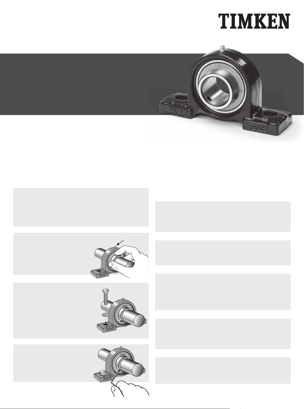
1.
2.
3.
Ensure that the shaft is clean, free from burrs, straight and
of proper diameter. The bearing should not be mounted on a
worn section of the shaft. Using shafts with hardness greater
than HRC 45 will reduce effectiveness of locking devices.
See table 2 for suggested shaft tolerances.
Install the supplied grease fitting
into the threaded lubrication hole
on the housing. Align the bearing
in its housing and slide the unit
into position on the shaft.
Bolt the housing tightly to its
mounting supports using an
appropriately sized fastener and
suggested bolt torque (table 4).
Flat washers should be used
when installing any kind of
housed unit. Washers should be
properly sized to bolt diameter.
Grease fitting in
lubrication hole
ADAPTER STYLE UNITS
Adapter style units have a tapered bore bearing mounted to the shaft with
adapter sleeve assembly, comprised of an adapter sleeve, locknut and
lockwasher. This design offers the best shaft concentricity and highest
capacity while having the ability to accommodate undersized shafting.
These units are most suitable where they are exposed to excessive
vibration and impact.
Installation procedures for adapter style units are shown below.
1.
2.
3.
4.
Ensure that the shaft is clean, free from burrs, straight and
of proper diameter. The bearing should not be mounted on
a worn section of the shaft. See table 5 for suggested shaft
tolerances.
Slide the adapter sleeve into position on the shaft. If the
sleeve is too tight, expand the slot by using a screwdriver
as required.
Slide the bearing unit over the adapter sleeve and loosely
install the housed unit to its mounting supports using an
appropriately sized fastener. Flat washers should be used
when installing any kind of housed unit. Washers should be
properly sized to bolt diameter.
Assemble the lockwasher on the sleeve and thread the
locknut onto the adapter sleeve leaving approximately 6.35
mm (¼ in.) between the lockwasher and the inner ring of
the bearing.
4.
Lock the bearing to the shaft
by tightening each inner ring
set screw incrementally to
suggested torque levels (see
table 3).
5.
Use a large screwdriver or pry bar to lever the sleeve into
position until there is no relative movement between the
shaft, adapter sleeve and the bearing’s inner ring.
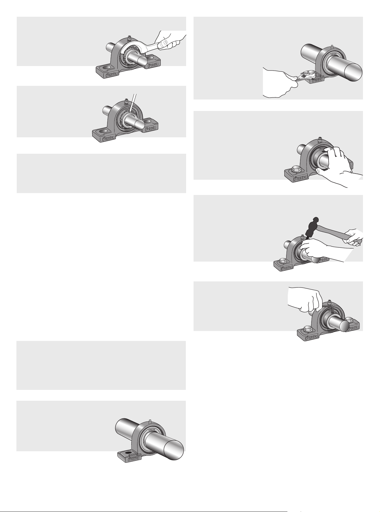
6.
7.
8.
Rotate the locknut until hand-tight. Use a spanner wrench
to tighten the locknut to
the suggested torque
(see table 6).
Bend a tang on the
lockwasher into a
slot on the locknut to
prevent the locknut
from loosening.
Rotate the shaft by hand while tightening the mounting bolts
to make sure the shaft rotates freely. Tighten the housed unit
mounting bolts to the recommended bolt tightening torque
given in table 4.
3.
4.
Bolt the housing tightly to its mounting supports using an
appropriately sized fastener and suggested bolt torque
(see table 4). Flat
washers should be
used when installing
any kind of housed
unit. Washers should
be properly sized to
bolt diameter.
Place the eccentric locking collar on the shaft with its
cam adjacent to the cam on the end of the bearing inner
ring. The eccentric collar’s
recessed cam will engage
the corresponding cam on
the bearing inner ring. Turn
the collar in the direction of
shaft rotation.
UEL SERIES
ECCENTRIC LOCKING COLLAR UNITS
The self-locking collar eliminates the need for locknuts, lockwashers,
shoulders, sleeves and adapters. For many agricultural and industrial
applications, self-locking collars are the easiest housed units to install.
The locking collar has a recessed cam made eccentric to the collar bore.
When assembled on the shaft, the locking collar engages or mates with
the eccentric cam end of a bearing’s inner ring. This assembly grips the
shaft tightly with a positive binding action that increases with use. No
adjustments of any kind are necessary. The collar set screw provides
supplementary locking.
Installation procedures for eccentric locking collar style units are
shown below.
1.
Ensure that the shaft is clean, free from burrs, straight and
of proper diameter. The bearing should not be mounted on a
worn section of the shaft. Using shafts with hardness greater
than HRC 45 will reduce effectiveness of locking devices.
See table 2 for suggested shaft tolerances.
5.
6.
Using a light weight hammer and a drift pin inserted in the
blind hole, tap lightly
in the direction of shaft
rotation to positively
engage the collar. The
insert is now locked to
the shaft.
Tighten the set screw to
suggested torque level (see
table 3).
2.
Install the supplied grease fitting into the threaded
lubrication hole on the housing.
Align the bearing in its housing
and slide the unit into position
on the shaft.
 Loading...