

Page 1

OPERATING MANUAL
MODEL PK-900 DATA CONTROLLER
Timewave Technology Inc.
PROPRIETARY INFORMATION
Reproduction, dissemination or use of information contained herein for
purposes other than operation and/or maintenance is prohibited without
written authorization from Timewave Technology Inc.
Page 2

PREFACE TO THE PK-900 OPERATING MANUAL
Please read this preface in its entirety. It contains information about how to
receive warranty service from Timewave and Timewave's software update policy.
RF Interference Information To User
This equipment has been tested and found to comply with the limits for a class B
digital device, pursuant to Part 15 of the FCC Rules. These limits are designed
to provide reasonable protection against harmful interference in a residential
installation. This equipment generates, uses and can radiate radio frequency
energy and, if not installed and used in accordance with Timewave's instructions, may
cause interference to radio and TV reception. However, there is no guarantee
that interference will not occur in a particular installation. If this
equipment does cause interference to radio or TV reception, which can be
determined by turning the PK-900 on and off, the user is encouraged to try to
correct the interference using one or more of the following measures:
o Re-orient the antenna of the device receiving interference.
o Relocate the PK-900 or computer with respect to this device.
o Plug the PK-900 into a different outlet so the PK-900 and the device are
on different branch circuits.
If necessary, the user should consult the dealer or an experienced radio/TV
technician for additional suggestions. The user may find "How to Identify and
Resolve Radio-TV Interference Problems", a booklet prepared by the FCC, helpful.
To comply with FCC part 15 limits the following must be followed:
o YOU MUST USE SHIELDED CABLE FOR ALL CONNECTIONS
o INTERNAL MODIFICATIONS TO THE PK-900 MAY INCREASE RF INTERFERENCE AND
VOID THE USERS AUTHORITY TO OPERATE THE UNIT
This PK-900 has been certified under Part 15 of the FCC rules.
Operation is subject to the following two conditions:
1. This device may not cause harmful interference.
2. This device must accept any interference received, including that
which may cause undesired operation.
As part of its continuing program of product improvement, Timewave reserves the
right to make changes in this product's specifications or documentation.
There may be inaccuracies or typographical errors in this document. Please
address comments and corrections to Timewave Technology Inc., 501 W. Law
son Ave,
St. Paul, MN 55117-4771. Timewave reserves the right to incorporate and issue any
information thus supplied in whatever manner it deems suitable without
incurring any obligations whatsoever.
Copyright Timewave Technology Inc., 2002. All rights reserved.
No part of this manual may be reproduced or used in any form or by any means
without prior written permission from the copyright owner.
12/02 i
Page 3

Welcome
Congratulations!! You've purchased another fine Timewave product.
PLEASE, before we go any further, may we ask you to FILL OUT AND RETURN the
Warranty Registration Card, which has been packed with your PK-900.
Product Update Policy
From time to time Timewave may make available updates to the design of its
products. We can only tell you about these updates if we have your warranty
card on file. PLEASE SEND IT IN if you have not already done so.
In Case of Trouble
Application and troubleshooting assistance may be obtained by calling Timewave during
our 8:00- 5:00 working hours in St. Paul, MN. Ask for the Technical
Support Department. The phone number is (651) 489-5080. Please have your
PK-900's serial number and version date of the software available. The
version date is on the first screen that comes up when you turn on the PK-900.
We will also need to know the nature of any other equipment connected to the
PK-900.
You may wish to attempt to solve problems locally, using other hams or an Timewave
dealer. A helpful Amateur with equipment similar to your own may literally be
just around the corner. Substituting another PK-900 or Data Controller that
you know is working properly for your questionable one is a diagnostic
technique that will check out the rest of your station. You may also try
running your PK-900 in another station if possible.
Timewave provides email Technical Support for its line of amateur radio equipment.
Email addresses are: [email protected] and [email protected]
If you call for assistance, please have your PK-900 up and running beside the
phone. Our Support technician will likely ask you to perform certain keyboard
routines to aid in diagnosis. If you have a voltmeter handy, you might have
the PK-900 open so you can report measurements to the technician.
Many of the Timewave products that are sent to us for repair are in perfectly good
order when we receive them. There is a test and alignment charge for units
returned to us in working order. Please perform whatever steps are applicable
from the installation sections of this manual to insure that there is a problem.
PLEASE DO NOT RETURN THE PK-900 TO US WITHOUT CONTACTING US FOR PERMISSION AND
AN RMA NUMBER. WE WOULD LIKE THE OPPORTUNITY TO TROUBLESHOOT THE PROBLEM OVER
THE PHONE FIRST, SAVING YOU BOTH TIME AND MONEY.
If the unit must be sent in, we will give you a Return to Manufacturer
Authorization (RMA) number over the telephone. This number allows us to track
your unit and provide you with its status. Please write this number on the
outside of the box so we may process your unit as quickly as possible.
1/93 ii
Page 4

If you send us the PK-900 by UPS it must be sent to the street address -
not the post office box number. The street address is:
Timewave Technology Inc.
1025 Selby Ave., Suite 101
St. Paul, MN 55104 USA
Attn. Technical Support
RMA # S????????? (obtain by telephone or email from Timewave)
We will need YOUR street address for UPS return - be sure to send it. Please
include your daytime telephone number in case we need to contact you for
further information.
UPS Gound (Brown Label) takes 5-6 days, Blue takes 2-3 days. Red is an
overnight service and is expensive. Send the PK-900 in a way that it can be
traced if we cannot verify receipt of shipment. We suggest UPS or FEDEX.
If the PK-900 is still under the original owner's warranty, Tmewave will pay the
cost of the return shipment to you. The current policy is that it will be
returned UPS Ground (Brown).
The PK-900 may be returned as the owner states in
his letter if he furnishes the return cost for the method he selects.
Typically, we will service the product in five to ten working days after it
has arrived at Timewave if we have all the facts. If we must call you, it may take
longer. PLEASE include a letter stating the problem and where you can be
reached by telephone. If you can be reached by phone in the evening on the
East Coast, let us know the number. Our current rate for non-warranty service
of the PK-900 is based on time and material and return shipping. Timewave is not
responsible for damage such as caused by lightning, nonprofessional alterations,
poor storage/handling, etc. We will make note of any shipping damage upon
receipt. See the inside back cover for Warranty information.
Should your warranty card not be on file at Timewave, you need to send the proof of
purchase date to receive warranty service. Typically a copy of your bill of
sale from an Timewave dealer will suffice.
The warranty is for the original owner only and is not transferable.
3/93 iii
Page 5

TABLE OF CONTENTS
CHAPTER 1 - INTRODUCTION
Paragraph Page
1.1 Overview................................................... 1-1
1.1.1 Capabilities.......................................... 1-1
1.1.2 Included Components................................... 1-1
1.2 Computer or Computer Terminal Requirements................. 1-2
1.3 Station Requirements....................................... 1-2
1.3.1 System Transmitter-Receiver Performance Requirements.. 1-2
1.4 PK-900 Specifications...................................... 1-3
1.4.1 Modem Characteristics................................. 1-3
1.4.2 Processor System...................................... 1-3
1.4.3 Input/Output Connections.............................. 1-4
1.4.4 Controls and Indicators............................... 1-4
1.4.5 General............................................... 1-4
CHAPTER 2 - COMPUTER INSTALLATION
2.1 Overview................................................... 2-1
2.1.1 Equipment Required.................................... 2-1
2.2 Unpacking the PK-900....................................... 2-1
2.2.1 Connecting Power...................................... 2-2
2.3 Connecting Your Computer or Computer Terminal.............. 2-3
2.3.1 IBM-PC/XT/AT and Compatibles.......................... 2-3
2.3.2 Apple Macintosh Series of Computers................... 2-3
2.3.3 Commodore 64 and 128 Computers........................ 2-3
2.3.4 Computer Terminal..................................... 2-4
2.4 Setting Up Your Communications or Terminal Software Program 2-4
2.4.1 Terminal Programs for IBM-PCs and Compatibles......... 2-4
2.4.2 Terminal Programs for the Apple Macintosh............. 2-5
2.4.3 Terminal Programs for the Commodore 64, 64C and 128... 2-5
2.5 System Startup and Loop-back Test.......................... 2-6
2.6 Detailed RS-232 Connections for Other Computers............ 2-9
2.6.1 Apple II Series....................................... 2-9
2.6.2 Commodore C-64, C-128 and Vic 20...................... 2-9
2.6.3 IBM PCjr.............................................. 2-9
2.6.4 Tandy Color Computer.................................. 2-10
2.6.5 Tandy Model 100/102 and NEC 8201...................... 2-10
2.6.6 Other Computers with RS-232-C Ports................... 2-10
2.6.7 Other Computers with Non-Standard Serial Ports........ 2-11
2.7 Terminal (Modem) Software for Other Computers.............. 2-11
2.7.1 Terminal Programs for the Apple II, II+, IIE and IIC.. 2-12
2.7.2 Terminal Programs for the Commodore Vic 20............ 2-12
2.7.3 Terminal Program for the IBM PCjr..................... 2-12
2.7.4 Terminal Programs for the Tandy Color Computer........ 2-12
2.7.5 Terminal Programs for the Tandy 100/102 and NEC 8201.. 2-12
1/93 TOC-1
Page 6

CHAPTER 3 - RADIO INSTALLATION
Paragraph Page
3.1 Overview................................................... 3-1
3.1.1 Equipment Required.................................... 3-1
3.2 Receive-Only Radio Connections............................. 3-1
3.3 Transmit and Receive Radio Connections..................... 3-2
3.3.1 Transceiver's Microphone or Accessory Connector?...... 3-2
3.3.2 Connections for Specific Transceivers................. 3-2
3.3.3 Check Your Transceiver's Operating Manual............. 3-3
3.3.4 Specific Connection Points............................ 3-3
3.3.5 Begin Assembling your Radio Cable..................... 3-4
3.3.5.1 Prepare the Radio Cable.......................... 3-4
3.3.5.2 Verify the Connection Points with Your Manual.... 3-4
3.3.5.3 Prepare the Connector............................ 3-4
3.3.5.4 Wire the Connector............................... 3-4
3.3.6 Wiring Your HF Transceiver for Direct CW Keying....... 3-6
3.3.7 Connections for Direct FSK Operation on RTTY.......... 3-6
3.4 PK-900 Configuration Jumpers and Connections............... 3-7
3.4.1 Push-To-Talk (PTT) Configuration...................... 3-7
3.4.2 PK-900 Connections.................................... 3-8
3.5 Transceiver Adjustments.................................... 3-8
3.5.1 FM Transceiver Final Adjustments...................... 3-8
3.5.2 SSB Transceiver Final Adjustments..................... 3-10
3.6 Oscilloscope Connections................................... 3-12
CHAPTER 4 - PACKET RADIO
4.1 Overview................................................... 4-1
4.1.1 Getting Started....................................... 4-1
4.1.2 Making the Loopback Connection........................ 4-1
4.2 Packet Introduction........................................ 4-2
4.3 VHF/UHF Packet Operation................................... 4-4
4.3.1 What You Should See................................... 4-6
4.3.2 What It Means......................................... 4-6
4.3.3 What Happens When You Connect......................... 4-9
4.3.3.1 Standard TNCs.................................... 4-9
4.3.3.2 Mailbox Message Systems.......................... 4-9
4.3.3.3 Packet Switches.................................. 4-10
4.3.4 Who Can I Talk To?.................................... 4-12
4.3.5 Your First Real Connect............................... 4-12
4.3.6 I'm Having Trouble Connecting......................... 4-13
4.4 More Packet Features....................................... 4-14
4.4.1 LCD Status and Mode Indicators........................ 4-14
4.4.2 Automatic Greetings................................... 4-16
4.4.3 Beacon Operation...................................... 4-17
4.4.4 Digipeater Details.................................... 4-17
4.4.4.1 Are You a Digipeater?............................ 4-18
4.4.5 Monitoring Other Stations............................. 4-18
4.4.5.1 Monitoring the Packet Networking Switches........ 4-19
4.4.5.2 Monitoring Other Stations While Connected........ 4-19
4.4.5.3 Selective Monitoring............................. 4-19
4.4.5.4 The MFILTER Command.............................. 4-20
4.4.5.5 Monitor Without Callsign Headers................. 4-19
4.4.5.6 MSTAMP, The Monitor Time-Stamp Command........... 4-20
4.4.6 Packet Connects....................................... 4-20
1/93 TOC-2
Page 7

CHAPTER 4 - PACKET RADIO (Continued)
Paragraph Page
4.4.6.1 Time-Stamping Connects........................... 4-20
4.4.6.2 Connect Alarm.................................... 4-20
4.4.7 Packet Formatting and Editing......................... 4-21
4.4.7.1 Carriage Returns and Linefeeds in Packets........ 4-20
4.4.7.2 Canceling Lines and Packets...................... 4-21
4.4.7.3 Redisplay........................................ 4-21
4.4.7.4 The PASS Character............................... 4-21
4.4.8 Packet Transmit Timing................................ 4-22
4.4.8.1 TXDELAY and AUDELAY.............................. 4-22
4.4.8.2 AXDELAY and AXHANG............................... 4-22
4.5 Packet Protocol Basics..................................... 4-23
4.5.1 Unconnected Packets................................... 4-23
4.5.2 Connected Packets..................................... 4-23
4.5.3 FRACK and RETRY....................................... 4-23
4.5.4 PACLEN and MAXFRAME................................... 4-24
4.5.5 Reducing Errors Through Collision Avoidance........... 4-24
4.5.6 CHECK and RELINK...................................... 4-24
4.6 Multiple Connection Operation.............................. 4-25
4.6.1 Multiple Connection Description....................... 4-25
4.6.2 The Channel Switching Character....................... 4-25
4.6.3 Will You Accept Multiple Connects..................... 4-26
4.6.4 Display Multiple Connected Callsigns.................. 4-26
4.6.5 Doubling Received CHSWITCH Characters................. 4-26
4.6.6 Checking Your Connect Status with the CSTATUS Command. 4-26
4.6.7 The MULT LCD.......................................... 4-26
4.7 HF Packet Operation........................................ 4-26
4.7.1 Where to Operate HF Packet............................ 4-27
4.7.2 PK-900 HF Packet Settings............................. 4-27
4.7.3 HF Receiver Settings.................................. 4-27
4.7.4 Tuning in HF Packet Stations.......................... 4-27
4.7.5 Transmitter Adjustments............................... 4-29
4.7.6 Going On The Air...................................... 4-29
4.8 Controlling the Radio Ports................................ 4-30
4.8.1 Selecting and Loading Modems.......................... 4-30
4.8.2 Displaying Received Data.............................. 4-31
4.8.3 Controlling Your Transmitted Text..................... 4-32
4.8.3.1 Define the Channel Switching Character CHSWITCH.. 4-32
4.8.3.2 Switching Between Radio Ports.................... 4-33
4.8.3.3 More Thoughts on Port Switching.................. 4-35
4.9 Advanced Packet Operation.................................. 4-36
4.9.1 Transparent Mode...................................... 4-36
4.9.2 Gateway Operation..................................... 4-36
4.9.3 Sending 8-bit Data in Converse Mode................... 4-37
4.9.4 The Packet QRA Feature................................ 4-37
4.9.5 The CFROM Command..................................... 4-37
4.9.6 Operating in Full-Duplex.............................. 4-37
4.9.7 Identifying as a Digipeater........................... 4-37
4.9.8 Digipeater Alias Callsign............................. 4-37
4.9.9 Morse ID in Packet.................................... 4-38
4.9.10 Sharing Packet Channels With Voice Operation.......... 4-38
4.9.11 Disabling Transmit Operation.......................... 4-38
4.10 Seldom Used Commands....................................... 4-38
1/93 TOC-3
Page 8

CHAPTER 4 - PACKET RADIO (Continued)
Paragraph Page
4.11 Packet Lite HF Packet Protocol Extension................... 4-38
4.11.1 Enabling Packet Lite.................................. 4-39
4.11.2 Compatibility With Standard AX.25 Stations............ 4-39
4.11.3 Packet Lite Protocol Enhancement Summary.............. 4-40
4.12 Packet Meteor Scatter Extension....................... 4-42
CHAPTER 5 - MAILDROP OPERATION
5.1 Overview of PakMail Operation.............................. 5-1
5.1.1 RAM Space for Message Storage......................... 5-1
5.1.2 System Commands....................................... 5-1
5.1.3 Your MailDrop Callsign................................ 5-1
5.1.4 Start and Stop MailDrop Operation..................... 5-1
5.2 Local Logon................................................ 5-2
5.2.1 Monitor MailDrop Operation............................ 5-2
5.2.2 Caller Prompts........................................ 5-2
5.3 SYSOP MailDrop Commands.................................... 5-3
5.4 Remote User MailDrop Commands.............................. 5-3
5.4.1 A (ABORT)............................................. 5-3
5.4.2 B (BYE)............................................... 5-4
5.4.3 E (Edit #)............................................ 5-4
5.4.4 H (HELP).............................................. 5-4
5.4.5 J (JLOG).............................................. 5-5
5.4.6 K n (KILL n [Mine])................................... 5-5
5.4.7 L (LIST [Mine])....................................... 5-5
5.4.8 R n (READ n [Mine])................................... 5-5
5.4.9 S callsign (SEND callsign)............................ 5-5
5.4.9.1 Sending Other Types of Messages with SEND........ 5-6
5.4.10 V (VERSION)........................................... 5-7
5.4.11 ? (HELP).............................................. 5-7
5.5 Sample MailDrop Session - The Remote User's Point of View.. 5-7
5.5.1 Connect and Logon..................................... 5-8
5.5.2 LIST Messages......................................... 5-8
5.5.3 READ Messages......................................... 5-8
5.5.4 KILL Messages......................................... 5-8
5.5.5 SEND Messages......................................... 5-9
5.5.6 Log Off and Disconnect................................ 5-9
5.6 Sample MailDrop Session - MailDrop SYSOP's Point of View... 5-10
5.6.1 Message Numbers....................................... 5-11
5.7 Auto-Forwarding with the PK-900 MailDrop................... 5-11
5.7.1 MailDrop Settings for Auto-Forwarding................. 5-11
5.7.2 Entering a Message for Reverse Forwarding............. 5-12
1/93 TOC-4
Page 9

CHAPTER 6 - BAUDOT AND ASCII RTTY OPERATION
Paragraph Page
6.1 Overview................................................... 6-1
6.2 Where to Operate Baudot and ASCII RTTY..................... 6-1
6.2.1 PK-900 Baudot RTTY Parameter Settings................. 6-1
6.2.2 HF Receiver Settings.................................. 6-2
6.2.3 Tuning in Baudot and ASCII Stations................... 6-2
6.3 Transmitter Adjustments.................................... 6-4
6.3.1 Going On The Air...................................... 6-4
6.4 A Typical Baudot RTTY Contact.............................. 6-4
6.4.1 Calling CQ............................................ 6-5
6.4.2 Answering a CQ........................................ 6-5
6.5 Baudot RTTY Operating Tips................................. 6-5
6.5.1 Changing Speed........................................ 6-6
6.5.2 Formatting Your Transmitted and Received Text......... 6-6
6.5.3 Sending a Synchronous Idle or DIDDLE.................. 6-7
6.5.4 Echoing Transmitted characters As Sent................ 6-7
6.5.5 Sending Only Complete Words........................... 6-7
6.5.6 Operating on the Wrong Sideband....................... 6-7
6.5.7 Framing Errors........................................ 6-7
6.5.8 UnShift-On-Space (USOS)............................... 6-7
6.5.9 Operating at Commercial or VHF Wide RTTY Shifts....... 6-8
6.5.10 The CODE Command for International RTTY Compatibility. 6-8
6.5.11 Copying Encoded RTTY Transmissions.................... 6-8
6.6 ASCII RTTY Operation....................................... 6-8
6.6.1 Starting ASCII Operation.............................. 6-8
6.6.2 ASCII RTTY Operating Tips............................. 6-9
6.6.3 Changing ASCII Baud Rates............................. 6-9
6.6.4 Operating at Commercial or Wide ASCII RTTY Shifts..... 6-10
6.6.5 Other RTTY Commands for ASCII Operation............... 6-10
6.7 Simultaneous RTTY and Packet Operation..................... 6-10
6.7.1 Selecting Modems...................................... 6-11
6.7.2 Displaying Received Data.............................. 6-12
6.7.3 Switching Between Ports............................... 6-12
6.7.4 More Thoughts on Port Switching....................... 6-14
1/93 TOC-5
Page 10

CHAPTER 7 - AMTOR AND NAVTEX OPERATION
Paragraph Page
7.1 Overview................................................... 7-1
7.2 Where to Operate AMTOR..................................... 7-1
7.2.1 PK-900 AMTOR Parameter Settings....................... 7-1
7.2.2 Entering Your SELective CALling Code (MYSELCAL)....... 7-1
7.2.3 Entering Your SELective CALling Code (MYIDENT)........ 7-2
7.2.4 Enter the AMTOR Mode.................................. 7-2
7.2.5 HF Receiver Settings.................................. 7-2
7.2.6 Tuning in AMTOR Stations.............................. 7-3
7.3 Transmitter Adjustments.................................... 7-5
7.3.1 Going On The Air...................................... 7-5
7.3.2 Calling CQ in FEC AMTOR............................... 7-5
7.3.3 Answering an FEC AMTOR CQ............................. 7-6
7.3.4 ARQ AMTOR Operating Fundamentals...................... 7-6
7.3.5 Ending an ARQ AMTOR Contact........................... 7-6
7.3.6 LCD Status and Mode Indicators........................ 7-7
7.4 AMTOR Operating Tips....................................... 7-8
7.4.1 ARQ Break-In (ACHG Command)........................... 7-8
7.4.2 Entering Your Auto-AnswerBack (AAB)................... 7-8
7.4.3 Operating AMTOR with Other Modems and Shifts.......... 7-9
7.4.4 Speed Change Not Permitted............................ 7-9
7.4.5 Echoing Transmitted Characters as Sent (EAS).......... 7-9
7.4.6 Sending Only Complete Words (WORDOUT)................. 7-9
7.4.7 Operating on the Wrong Sideband....................... 7-10
7.5 Monitoring ARQ AMTOR Contacts with ALIST................... 7-10
7.6 AMTOR MailDrop Operation................................... 7-10
7.6.1 Special Operation Considerations...................... 7-10
7.6.2 Settings For AMTOR MailDrop Operation................. 7-11
7.6.3 Starting AMTOR MailDrop Operation..................... 7-11
7.6.4 Local Logon to the MailDrop........................... 7-11
7.6.4.1 Remote Logon to your AMTOR MailDrop.............. 7-11
7.6.5 Caller Prompts........................................ 7-12
7.6.6 Monitor MailDrop Operation............................ 7-13
7.6.7 SYSOP MailDrop Commands............................... 7-13
7.6.8 Remote User MailDrop Commands......................... 7-13
7.6.8.1 A (ABORT) (Remote only).......................... 7-13
7.6.8.2 B (BYE).......................................... 7-13
7.6.8.3 H (HELP)......................................... 7-13
7.6.8.4 J (JLOG) (Remote Only)........................... 7-13
7.6.8.5 K n (KILL n [Mine]).............................. 7-13
7.6.8.6 L n (LIST [Mine])................................ 7-14
7.6.8.7 R n (READ n [Mine]).............................. 7-14
7.6.8.8 S callsign (SEND callsign)....................... 7-14
7.7 Simultaneous AMTOR and Packet Operation.................... 7-14
7.7.1 Selecting Modems..................................... 7-15
7.7.2 Displaying Received Data.............................. 7-16
7.7.3 Switching Between Ports............................... 7-16
7.7.4 More Thoughts on Port Switching....................... 7-18
7.7.5 Dual Port AMTOR/Packet MailDrop Operation............. 7-18
7.7.5.1 Packet MailDrop Command Settings................. 7-19
7.7.5.2 AMTOR MailDrop Command Settings.................. 7-19
7.7.5.3 Dual Port MailDrop Operation Notes............... 7-19
7.8 AMTOR Switching-Time Considerations........................ 7-19
7.8.1 Suggested AMTOR Operating Settings.................... 7-20
7.8.2 Possible Areas for AMTOR Performance Improvement...... 7-20
7.9 NAVTEX Operation........................................... 7-21
1/93 TOC-6
Page 11

CHAPTER 8 - MORSE OPERATION
Paragraph Page
8.1 Overview................................................... 8-1
8.2 Where to Operate Morse..................................... 8-1
8.2.1 Entering the Morse Mode............................... 8-1
8.2.2 HF Receiver Settings.................................. 8-1
8.2.3 Tuning in Morse Stations.............................. 8-1
8.3 Going On The Air........................................... 8-2
8.3.1 A Typical Morse Contact............................... 8-3
8.4 Morse Operating Tips....................................... 8-3
8.4.1 The PK-900 Morse Modem................................ 8-4
8.4.2 Speed Change (MSPEED)................................. 8-4
8.4.3 Echoing Transmitted Characters As Sent (EAS).......... 8-4
8.4.4 Sending Only Complete Words (WORDOUT)................. 8-4
8.4.5 Speed Lock (LOCK)..................................... 8-4
8.5 Special Morse Characters................................... 8-5
8.6 Morse Code Practice........................................ 8-5
CHAPTER 9 - FACSIMILE (FAX) OPERATION
9.1 Overview................................................... 9-1
9.1.1 Facsimile............................................. 9-1
9.1.2 Slow Scan Television.................................. 9-2
9.2 Finding FAX Frequencies.................................... 9-2
9.2.1 Finding SSTV Frequencies.............................. 9-3
9.3 FAX and SSTV Analog Signal Operation....................... 9-3
9.4 Black & White FAX Operation................................ 9-4
9.4.1 HF Receiver Settings.................................. 9-4
9.4.2 Tuning In HF Facsimile Stations....................... 9-4
9.4.3 PK-900 Facsimile Parameter Settings................... 9-5
9.5 Receiving Facsimile Broadcasts............................. 9-5
9.6 Facsimile Operating Tips................................... 9-6
9.6.1 Setting PRTYPE ....................................... 9-6
9.6.2 Printing Direction (LEFTRITE)......................... 9-6
9.6.3 Inverting Black and White (FAXNEG).................... 9-7
9.6.4 Display Density (GRAPHICS)............................ 9-7
9.7 Displaying Other Services.................................. 9-7
9.7.1 The PK-900 FAX Modem.................................. 9-7
9.8 Transmitting FAX........................................... 9-7
9.9 Adjusting the PK-900 4.0 MHz Master Oscillator............. 9-8
1/93 TOC-7
Page 12

CHAPTER 10 - SIGNAL IDENTIFICATION AND TDM OPERATION
Paragraph Page
10.1 Overview................................................... 10-1
10.2 SIAM Operation............................................. 10-1
10.2.1 Tuning In FSK Narrow and Wide Stations................ 10-2
10.3 Using the SIAM Mode........................................ 10-4
10.3.1 Copying Encoded RTTY Transmissions.................... 10-4
10.3.2 The CODE Command for International RTTY Compatibility. 10-5
10.4 TDM Receive Operation...................................... 10-5
10.4.1 TDM Parameters........................................ 10-5
10.4.2 Monitoring TDM Signals................................ 10-5
10.4.3 Where to Find TDM Signals............................. 10-6
CHAPTER 11 - PACTOR OPERATION
11.1 Overview................................................... 11-1
11.2 Where to Operate PACTOR.................................... 11-1
11.3 PK-900 Parameter Settings.................................. 11-2
11.3.1 Entering Your Callsign (MYPTCALL)..................... 11-2
11.3.2 Entering the PACTOR Mode.............................. 11-2
11.4 HF Receiver Settings....................................... 11-3
11.5 Tuning in PACTOR Stations.................................. 11-3
11.6 Operating on PACTOR........................................ 11-4
11.6.1 Going On the Air...................................... 11-5
11.6.2 Calling CQ in Unproto Mode............................ 11-5
11.6.3 Answering an Unproto PACTOR CQ........................ 11-6
11.6.3.1 Ending an ARQ PACTOR Contact..................... 11-7
11.6.4 Long Path Contacts.................................... 11-7
11.6.5 LCD Status and Mode Indicator......................... 11-8
11.7 PACTOR Operating Tips...................................... 11-9
11.7.1 ARQ Break-In (ACHG Command)........................... 11-9
11.7.2 Entering Your Auto-Answer Back (AAB).................. 11-9
11.7.3 Operating PACTOR on Other Modem Frequencies and Shifts 11-10
11.7.4 Automatic Speed Change................................ 11-10
11.7.5 Echoing Transmitted Characters As Sent (EAS).......... 11-10
11.7.6 Sending Only Complete Words (WORDOUT)................. 11-11
11.7.7 Operating on the Wrong Sideband....................... 11-11
11.7.8 Little Used PACTOR Commands........................... 11-11
11.8 Monitoring ARQ PACTOR Contacts with PTL.................... 11-12
11.9 PACTOR MailDrop Operation.................................. 11-12
11.9.1 Special Operating Considerations...................... 11-12
11.9.2 Settings For PACTOR MailDrop Operation................ 11-13
11.9.3 Starting PACTOR MailDrop Operation.................... 11-13
11.9.4 Local Logon to the MailDrop........................... 11-13
11.9.4.1 Remote Logon to your PACTOR MailDrop............. 11-13
11.9.5 Caller Prompts........................................ 11-13
11.9.6 Monitor MailDrop Operation............................ 11-14
11.9.7 SYSOP MailDrop Operation.............................. 11-14
3/93 TOC-8
Page 13

Paragraph Page
11.9.8 Remote User MailDrop Commands......................... 11-14
11.9.8.1 A (ABORT) (Remote Only).......................... 11-14
11.9.8.2 B (BYE).......................................... 11-14
11.9.8.3 H (HELP)......................................... 11-14
11.9.8.4 J (JLOG)......................................... 11-14
11.9.8.5 K n (KILL n [MINE]............................... 11-14
11.9.8.6 L (LIST [MINE]).................................. 11-15
11.9.8.7 R n (READ n [MINE]).............................. 11-15
11.9.8.8 S callsign (SEND callsign)....................... 11-15
11.9.8.9 V (VERSION)...................................... 11-15
11.9.8.10 ? (HELP)......................................... 11-15
11.10 Simultaneous PACTOR and Packet Operation.............. 11-15
11.10.1 Selecting Modems................................. 11-16
11.10.2 Displaying Received Data......................... 11-16
11.10.3 Switching Between Ports.......................... 11-17
11.10.4 More Thoughts on Port switching.................. 11-19
11.10.5 Dual Port PACTOR/Packet Maildrop Operation....... 11-19
11.10.5.1 Packet MailDrop Command Settings............ 11-20
11.10.5.2 PACTOR MailDrop Command Settings............ 11-20
11.10.5.3 DualPort MailDrop Operation Notes........... 11-20
11.11 PACTOR Switching Time Considerations.................. 11-21
11.11.1 Suggested PACTOR Operating Settings.............. 11-21
11.11.2 Possible Areas For PACTOR Performance Improvement 11-21
APPENDICES
APPENDIX A PK-900 COMMAND SUMMARY
APPENDIX B PK-900 SCHEMATIC DIAGRAM
APPENDIX C PK-900 PARTS PICTORIAL
APPENDIX D SELF TEST ROUTINE
APPENDIX E SPECIFIC RADIO CONNECTIONS
APPENDIX F WARRANTY
3/93 TOC-9
Page 14

The rest of this page is blank.
3/93 TOC-10
Page 15

CHAPTER 1
INTRODUCTION
1.1 Overview
The PK-900 was designed by AEA to provide you the Amateur the
complete digital operating position when coupled with a Personal
Computer or Computer Terminal. The PK-900 couples your HF or
VHF/UHF (or both) voice transceivers to your computer or terminal so
you can use its keyboard and display to "talk" to other Amateurs.
1.1.1 Capabilities
The PK-900 allows you to transmit and receive all legal Amateur
digital modes that are popular on both HF and VHF. In addition you
can send and receive black-and-white Weather FAX. The PK-900 can
receive other modes such as TDM, NAVTEX and bit-inverted Baudot RTTY.
These capabilities together with SIAM (Signal Identification and
Acquisition Mode) make the PK-900 ideal for the digital Short Wave
Listener as well.
The PK-900 with your Computer or Terminal allows you to transmit and
receive the following modes:
o AX.25 Packet, both HF and VHF (Chapter 4)
o Baudot and ASCII RTTY (Chapter 6)
o AMTOR/SITOR CCIR Rec. 476 and 625 (Chapter 7)
o Morse Code (Chapter 8)
o HF Weather FAX (Chapter 9)
o PACTOR (Chapter 11)
In addition the PK-900 receives the following modes:
o NAVTEX marine broadcasts (Chapter 7)
o TDM (Time Division Multiplex) signals (Chapter 10)
o Bit-inverted Baudot RTTY (Chapter 10)
The PK-900 also has the following special features:
o SIAM for SWLing (Chapter 10)
o PakMail Maildrop for Automatic Packet Message Handling (Chapter 5)
o AMTOR MailDrop Operation (Chapter 7)
o KISS mode for TCP/IP and special Packet applications (Appendix A)
o HOST mode for Host application programs (Technical Manual)
o Dualport operation with gateway (Chapter 4)
1.1.2 Included Components
Your PK-900 Data Controller package contains the following items:
o One PK-900 Data Controller
o PK-900 Operating Manual (this manual)
o Cables to connect your PK-900 to two separate radios
o Connector package to help set up your PK-900
o Radio Port "Loop-back" connector with jumper
o RS-232 Serial Cable with a DB-25 connector
3/93 1-1
Page 16

1.1.3 OPTIONS
o 9600 Baud internal G3RUH/K9NG compatable modem.
o AEA-FAX 900 HF Gray-scale fax reception program
1.2 Computer or Computer Terminal Requirements
You will need a Computer or Computer Terminal to "talk to" or control
your PK-900. If you are using a Computer, you will need a
Communications Program or Terminal Program as it is sometimes called.
The most popular computers are the IBM-PC and its compatibles, the
Apple Macintosh and the Commodore-64/128. These, and most other
computers can be made to work with the PK-900.
Although not required, AEA has program packages for the IBM-PC and the
Macintosh computers that are customized for radio communications.
These packages are PC-PAKRATT II with FAX for the IBM-PC and
compatibles, and MACRATT with FAX for the Apple Macintosh. Details of
how to connect each of these computers to the PK-900 can be found in
Chapter 2 of this manual. You may use other computers than those
mentioned above if the following technical requirements are met.
The Computer or Computer Terminal you plan to use must have an RS-232
Serial Communications port. You will also need a Communications
Program that allows your computer to communicate over the RS-232 port
using the ASCII character set. Details for connecting many computers
can be found in Chapter 2 of this manual.
1.3 Station Requirements
We presume that you already have an operating radio transceiver or
Short-Wave receiver to which you will connect your PK-900. In the
Amateur bands most of the VHF activity occurs on the 2-meter FM band,
while most of the HF activity occurs on the 20-meter band. An HF
receiver or transceiver must be capable of SSB operation. While no
specific brand of transceiver is required, we recommend that a modern
transceiver (built in the last 20 years) capable of operation on one
of the two frequency bands mentioned above be used. Specific
transceiver connections are described in Chapter 3 of this manual.
1.3.1 System Transmitter-Receiver Performance Requirements
Most modern radio transceivers are capable of excellent performance
in Morse, Baudot and ASCII RTTY, AMTOR and packet radio. Although
AMTOR Mode A (ARQ) operation imposes more demanding switching speed
requirements than the other operating modes, most radios will operate
in both AMTOR modes without any modifications. Radio switching times
are less critical in packet radio operation. See the AMTOR operating
section for further details on timing requirements.
Your PK-900 provides software-controlled timing variations that
permits operation with nearly all the HF and VHF/UHF radios in general
use today.
8/93 1-2
Page 17

1.4 PK-900 Specifications
As part of its program of product improvement, AEA reserves the right
to make changes in this product's specifications. Changes may also be
made to the information in this document and incorporated in revisions
to this manual. Prices and specifications are subject to change
without notice or obligation.
1.4.1 Modem Characteristics
Port 1:
Demodulator: Programmable Limiter-discriminator type,
preceded by an 8-pole Chebychev 0.5-dB
ripple bandpass filter.
Receive Band-pass: Automatically switched by operating mode
VHF packet: Center frequency 1700 Hz,
HF (except CW) Center frequencies: 1700, 2210,
2337.5 or 2550 Hz depending on
frequency shift chosen.
Bandwidth: 200, 470, 725, or 1150,
optimized for operating mode.
CW Center frequency 750 Hz,
bandwidth 200 Hz
Modulator Crystal controlled, 1 Hz step
programmable, phase-continuous, Direct
Digital Synthesis sine wave generator
Output Level: 5 to 100 millivolts RMS into 600 Ohms,
adjustable by a rear-panel control
Port 2:
Modulator/Demodulator AMD 7910 'World Chip' FSK Modem
Modem Tones: Bell 103 and 202
Output Level: 5 to 100 millivolts RMS into 600 Ohms,
adjustable by a rear-panel control
Options: 9600 baud direct FSK packet modem
(G3RUH/K9NG compatible)
Grey scale HF FAX receiving program
1.4.2 Processor System
Protocol conversion: Zilog Z-180 (64180) microprocessor
RAM: 64 Kilobytes
ROM: Up to 256 Kilobytes of ROM may be used
Display and memory ARQ
processor: 68HC05B4
DSS processor: 68HC05C4
Hardware HDLC: Zilog 8530 SCC
8/93 1-3
Page 18

1.4.3 Input/Output Connections
Radio Interface: Two five-pin DIN connectors;
Input/Output Lines Receive audio
Transmit audio
+/- Push-To-Talk (PTT) (+25 / - 40 VDC)
External squelch input
Ground
Direct FSK Outputs: Normal and reverse for each radio port
CW keying Outputs: Positive: +100 VDC max, at up to 100 mA
Negative: -30 VDC max, at up to 20 mA
Terminal Interface: RS-232-C 25-pin DB-25S connector
Input/Output RS-232-C with full handshake (hardware
and software)
Terminal Data Rates Autobaud selection of 110, 150, 300, 600,
1200, 2400, 4800, 9600 and 19200 BPS.
1.4.4 Controls and Indicators
Front Panel Indicators: Twenty-segment, selectable display
type: discriminator, magic eye or
zero center bargraph indicator for
tuning radio port 1.
Power Switch Front panel push-on push-off
Threshold Control Front panel knob controlling DCD
sensitivity of radio port 1 demodulator
Status Display LCD Status Display, with variable
intensity backlight, showing
Mode and data controller status
for both radio ports
1.4.5 General
Power Requirements: +13 VDC (12 to 16 VDC) at 1100 mA (max)
880 mA with LCD back light off
Mechanical: Overall, W 11 13/16" x D 12" x H 3.1/2"
(300 mm X 305 mm X 89 mm)
Weight 6 pounds 4 oz. (2.84
kilograms)
1/93 1-4
Page 19

CHAPTER 2
COMPUTER INSTALLATION
2.1 Overview
In this chapter we will connect the PK-900 to the RS-232 Serial port
of your Computer or Computer Terminal. After the Serial connection
has been made we will perform a quick check of the internal software.
Finally we will check the PK-900's modem by performing a Packet
"loop-back" test. When you have completed this chapter, you will be
ready to connect the PK-900 to your receiver or transceiver and
begin using it on the air.
2.1.1 Equipment Required
You will need the following for this chapter:
o your PK-900 Data controller;
o a 13.6-volt DC, 1.5-amp (or greater) regulated power supply such
as those sold by Radio Shack (or a Timewave AC-5 or AC-4);
(the power supply must be able to supply at least 13 VDC to the
PK-900 while it is operating under load)
o the included PK-900 DC power cord unless the AC-4 is used;
o your Computer or Computer Terminal;
o a Communications or Terminal Emulation program for your computer;
(not needed if a Computer Terminal is being used)
o the included RS-232 cable with a 25-pin "D" connector on each
end;
o one of the included 5-pin shielded "radio cables";
(note that the radio cables may arrive as a single 10-ft. cable
which should be cut in half producing two 5-ft. cables.)
o The two, wire "Loop-back" jumpers necessary for testing;
o wire cutters and strippers or a small pocket knife, a small
straight-blade screwdriver and a medium Phillips-head screwdriver.
2.2 Unpacking the PK-900
Carefully remove the PK-900 from the box and its plastic bag.
Inspect the unit for signs of damage that may have occurred in
shipping. If there is visible damage, please contact the dealer or
shipper. Do not attempt to install or use a damaged PK-900.
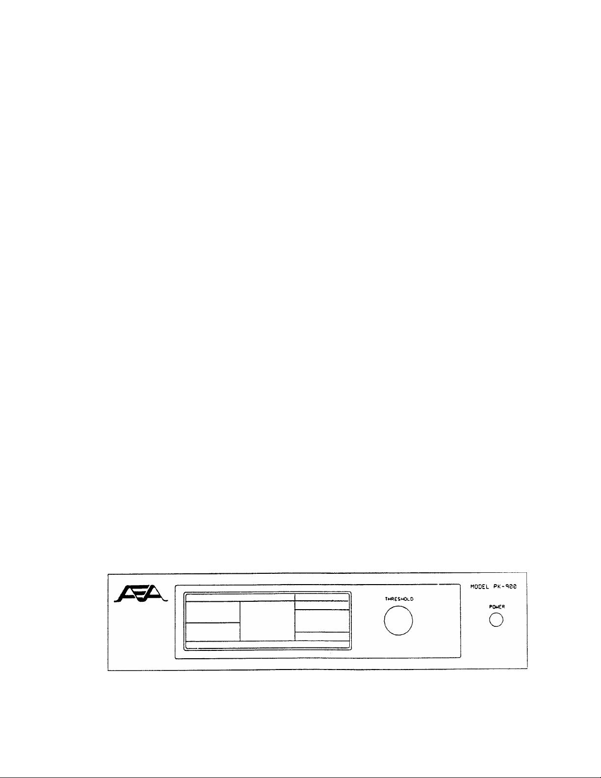
We will be discussing some of the Controls, Indicators and
Connections in this installation so take a few moments to
familiarize yourself with them. The figures on the next pages may
help with their locations.
1/93 2-1
Page 20
2.2.1 Connecting Power
MAKE SURE YOUR POWER SUPPLY IS OFF AND UNPLUGGED BEFORE WIRING
1. If you are using the AEA AC-4 or Timewave AC-5, skip to 5.
Otherwise, locate the PK-900 Power Cable in the accessory bag
. Strip off just enough insulation from the ends to connect it to
your 13-14 Volt DC regulated power supply.
2. The Center pin of the coaxial power plug is POSITIVE. Connect
the lead with the White stripe to the POSITIVE (+) lead on your
power supply. Check this with an Ohm-meter if you have one.
3. Connect the solid Black (GROUND) lead to the NEGATIVE (-) lead of
your power supply.
4. Connect the power plug to the 13 VDC Power Receptacle on the left
rear of the PK-900. DO NOT CONNECT YOUR COMPUTER YET.
5. Plug in your power supply or AC-4 and turn on power. Turn on
the PK-900 by depressing the Power Switch on the front of the
unit. At power-on, the LCD Status display on the left should
light. At this point, turn OFF the PK-900 and move on to
section 2.3.
If the Status display does not light, then re-check the above steps to
insure that 12-14 VDC is available at the power plug and the center
pin is POSITIVE.
If the Status display lights, and status indicators other than the
DCD indicators are displayed, then the PK-900 has already been
initialized. If the PK-900 has been initialized it is ready to
communicate with a computer or terminal at a specific baud rate
(probably 300, 1200, 2400, 4800 or 9600 baud). If you know what
this baud rate is then you should continue with the installation at
section 2.3 keeping this in mind.
If you do not know the baud rate the PK-900 has been initialized to
then you should reset the PK-900 by holding the rear-panel RESET
switch at the same time you turn on the power switch. After this is
done, no status indicators on the LCD Status display should be on
with the possible exception of either or both of the two DCD
indicators.
If the above did not produce the blank status indication, (ignoring
the DCD indicators) contact the Timewave Technical Support Department
as described in the front of this manual.
Figure 2-1 PK-900 Front Panel Controls and indicators
1/93 2-2
Page 21
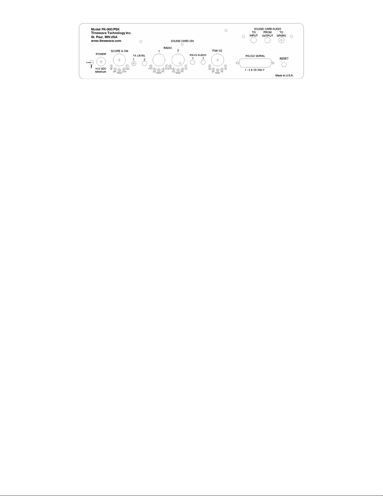
Figure 2-2 PK-900 Rear Panel Connections and Controls
2.3 Connecting Your Computer or Computer Terminal
MAKE SURE THE PK-900 AND YOUR COMPUTER ARE SWITCHED OFF
o Locate the PK-900 Serial Cable. Connect the 25-pin Female
connector to the RS-232 connector on the PK-900 rear panel.
o Connect the other end of this cable (Female DB-25) to the RS-232
Serial Port of your personal computer or Computer Terminal.
Details on connecting to common machines are listed below.
NOTE: This cable was designed to connect directly to a 25-pin IBM-PC
compatible RS-232 port. Many machines on the market today support
this configuration. Some less-common machines are listed in section
2.6. Please be certain you have properly connected the PK-900 to
your RS-232 computer or Terminal then proceed to section 2.4.
2.3.1 IBM-PC/XT/AT and Compatibles
IBM compatible 25-pin RS-232 serial ports should connect directly to
the supplied serial cable. Some IBM compatible machines are equipped
with a 9-pin serial port. For these machines a DB-9 to DB-25 adapter
should be obtained from a Radio Shack store or a computer dealer.
2.3.2 Apple Macintosh Series of Computers
AEA presently sells the program MacRATT with FAX which contains the
serial cable for the newer models of the Macintosh (models Mac + and
later). If you intend to use another communications program with the
PK-900 a Modem adapter cable must be purchased from your Apple
dealer to connect the Mac to your PK-900. For the newer machines
such as the Mac +, Mac SE and Mac II, a mini-8 to DB-25 adapter cable
is required (included with the AEA MACRATT with FAX program). For the
older Mac 128 and 512 machines, a DB-9 to DB-25 adapter cable from
your Apple dealer is needed.
2.3.3 Commodore 64 and 128 Computers
The Commodore 64/128 computers do not have an RS-232 port as standard
equipment. For these machines RS-232 adapters are available from
manufacturers such as Commodore or OMNITRONIX. These may work with
modem or terminal programs for your Commodore. Section 2.4 of this
chapter deals more with programs for personal computers. The AEA
Program COM-PAKRATT With FAX is NOT recommended for the PK-900.
1/93 2-3
Page 22

2.3.4 Computer Terminal
If you have an RS-232 Computer Terminal, sometimes called a Dumb Terminal, Smart-Terminal or ASCII-Terminal, you may need to change the
gender of the cable provided with your PK-900. This can be
accomplished with an inexpensive double-male RS-232 gender changing
adapter available from Radio Shack and other computer dealers. The
Radio Shack part number is 26-243.
2.4 Setting Up Your Communications or Terminal Software Program
If you will be using your PK-900 with a Computer, you will need to
read parts of this section to set up your Communications or Terminal
Software. If you will be using your PK-900 with a Terminal you will
not need any software and may skip to section 2.5.
Setting up a communications program for your PK-900 is very
important. How your screen looks when you use your PK-900 depends
completely on your Communications program. AEA currently makes
available programs for the IBM-PC and compatibles and the Apple
Macintosh computers. These products are customized for radio
communications and are available at extra cost from your AEA
dealer.
The PK-900 operates in much the same manner as a telephone modem and
most modem Terminal Programs will control a PK-900 quite nicely.
Some of these programs are "Public Domain" which means they are FREE.
Other Terminal Programs are "Share-ware" which means you may get them
from a friend and try them before you buy them. Whether you are using
an AEA program or one of your own choosing, see the section below for
the particular type of computer you plan to use.
2.4.1 Terminal Programs for IBM PCs and Compatibles
Although you can use almost any terminal program with your IBM PC or
close compatible, AEA currently sells the PC-PAKRATT II w/FAX program
which provides many features not available in "telephone modem"
programs. See your AEA dealer for information on PC-PAKRATT II w/FAX.
If you already have the PC-PAKRATT II program, follow the program
manual and install the software on your computer. You should also
read through the PACKET OPERATION chapter of the PC-PAKRATT II manual.
Familiarity with Packet operation of PC-PAKRATT will be necessary for
performing a quick-check of the PK-900 in section 2.5 of THIS
manual.
As we mentioned above, an AEA program is not required to use the
PK-900. Many terminal programs can be found throughout the amateur
radio community or can be downloaded from Compuserve, GEnie and from
many telephone bulletin boards.
A partial list of PC programs tested with the PK-900 includes:
PROCOMM, CROSSTALK-XVI, SMARTCOMM, RELAY, BITCOM, QMODEM, PC-TALK,
CTERM, HAMCOM, HAMPAC, YAPP and the terminal program included with
Microsoft Windows 3.0 (tm).
1/93 2-4
Page 23

Follow the installation directions that come with the Terminal
program you wish to use. Once installed on the computer, you
should start the program and set the communication parameters for
the following:
Data Rate = 1200 bits per second (Bauds)
Data bits = 7
Parity = EVEN
Stop bits = 1
Once these settings have been achieved and the correct serial
communications port chosen, you may proceed to section 2.5.
2.4.2 Terminal Programs for the Apple Macintosh
Although you can use almost any terminal program with your Macintosh,
AEA presently sells the MACRATT with FAX program which provides many
features not available in "telephone modem" programs. See your AEA
dealer for information on MACRATT with FAX.
If you already have the MACRATT program, please follow the program
manual and install the software on your Mac. You should also read
through the PACKET OPERATION chapter of the MACRATT manual.
Familiarity with Packet operation of MACRATT will be necessary for
performing a quick check of the PK-900 in section 2.5 of THIS
manual.
As we mentioned above, an AEA program is not required to use the
PK-900. Many terminal programs can be found throughout the amateur
radio community and can be downloaded from Compuserve, GEnie and from
many telephone bulletin boards.
A partial list of Mac programs tested with the PK-900 includes:
MAC TERMINAL, RED RYDER, MICROPHONE, SMARTCOMM II and MOCK TERMINAL
Follow the installation directions that come with the Terminal program
you wish to use. Once installed on the computer, you should start the
program and set the communication parameters for the following:
COMPATIBILITY:
1200 bauds, 7 bits/character, even parity, Handshake XON/XOFF,
FULL-DUPLEX, Modem connection, "telephone" port.
Once these settings have been achieved, proceed to section 2.5.
2.4.3 Terminal Programs for the Commodore 64, 64C and 128
Although AEA presently sells the COM-PAKRATT with FAX program package
for the PK-232, this program cannot access all the features of the
PK-900. AEA therefore cannot recommend using the COM-PAKRATT
package with the PK-900. If you already have this package, it will
certainly get you started with the PK-900 by using the "Dumb
Terminal" mode. You may wish to find another program which provides
more features than are available in the COM-PAKRATT program in the
Dumb Terminal Mode. Other ideas for terminal programs for the
Commodore-64 series of computers are listed below.
1/93 2-5
Page 24

Many terminal programs can be found throughout the amateur community
or can be downloaded from Compuserve and from many telephone
bulletin boards. In addition a BASIC communications program is
listed in the Programmer's Reference Guide published by Commodore.
Use the program listing for "True ASCII". We suggest you operate
your PK-900 at 300 bauds with these computers to avoid possible
speed difficulties.
Follow the installation directions that come with the Terminal program
you wish to use. Once installed on the computer, you should start the
program and set the communication parameters for the following:
Data Rate = 300 bits per second (Bauds)
Data bits = 7
Parity = EVEN
Stop bits = 1
Once these settings have been achieved, proceed to section 2.5.
2.5 System Startup and Loop-back Test
Make sure that you have connected your PK-900 to a 12-14 Volt DC
power source and to the RS-232 port of your computer or Terminal.
If you are using a computer, you must also have a communications
program and be familiar with its operation. You are now ready to
begin the following PK-900 Startup and Loop-back test procedure.
1. Don't connect any cables to your radio yet!
2. Remove the 16 gauge wire "Loop-back" connectors from the
PK-900 accessory bag.
3. Plug these into pins 1 and 4 of each of the radio connectors on
the PK-900's rear panel.
4. Set both AFSK levels on the back panel of the PK-900 to 50%
rotation (straight up and down) using a small screwdriver.
5. Turn on your computer. Load and run your communications program.
If you are using an AEA PAKRATT program, follow the program
instructions to enter the Packet mode, then skip to step 11.
If you are using another Terminal Program or a Computer Terminal,
Set your computer's terminal program to:
o 1200 bauds (if available);
o seven-bit word;
o even parity;
o one stop bit.
NOTE: You may use other terminal baud rates with the PK-900 - we
recommend 1200 baud here to keep this procedure easy and consistent.
6. Press the PK-900's power switch to the ON position.
At power-on, the LCD Status display on the left should light,
1/93 2-6
Page 25

showing either no status indications or one or both of the DCD
indicators. If the Status display lights and other status
indicators are displayed, then the PK-900 has already been
initialized. If you know the terminal baud rate the PK-900 has
been set to, you may proceed to step 11; otherwise you must
reset the PK-900 as described below.
To reset the PK-900, simply hold the rear-panel RESET switch in
at the same time you turn on the power switch. After this is
done, then the only LCD Status indicators showing may be the DCD
indicators. If your serial port is operating at 1200 bauds as we
recommend, you'll see the "autobaud" message:
Please type a star ( * ) for autobaud routine.
If your serial port is operating at 300, 2400, 4800 or 9600
bauds, you may see some "garbage" characters.
This is normal and you should proceed with step 7.
7. Type an asterisk (*). When the PK-900 has "recognized" your
computer's data rate, the CMD LCD will light. Your screen will
then display the sign-on message:
PK-900 is using default values.
AEA PK-900 Data Controller
Copyright (C) 1986-1993 by
Advanced Electronic Applications, Inc.
Release DD.MMM.YY
cmd:
Make note of the Release date on the first page of this manual.
This is important should you ever call AEA for technical support.
It should match the firmware release sticker on the bottom of
your PK-900.
8. If you are using an AEA program, follow the instructions in the
program manual to enter the packet callsign (MYCALL) of AAA into
the PK-900. Even though this is not your callsign, please do
this for this procedure. You must change it to YOUR OWN CALLSIGN
after completing this procedure.
If you are using a Computer Terminal or a non-AEA terminal
program the following will set your packet callsign to AAA:
Enter MYCALL by typing MY AAA <Enter> (or <RETURN>).
(<RETURN> or <Enter> means type the single key on your keyboard.)
Your monitor should display:
MYcall was PK900/PK900
MYcall now AAA/PK900
9. If you are using an AEA program follow the instructions to
CONNECT in packet mode to AAA. Since you have just entered your
callsign as AAA, you will connect to yourself.
If you are using a Computer Terminal or a non-AEA program,
1/93 2-7
Page 26

entering the following after the "cmd:" command mode prompt
will cause the PK-900 to Connect to AAA:
C AAA <Enter>
After a few moments, your monitor should display:
*** CONNECTED to AAA
10. Type HELLO SELF <Enter>
After a few moments, your monitor should echo the same message.
If you have gotten this far then the digital section of the
PK-900 and the VHF packet modem of port 1 are both working.
11. We will now check the PK-900's HF modem. If you are using an
AEA program, follow the instructions to select the HF modem by
turning the VHF Parameter OFF; this will automatically set the
radio baud rate HBAUD to 300 for HF packet work.
If you are using a Computer Terminal or a non-AEA terminal
program, the following sets the HF mode of the PK-900:
Type <CONTROL-C>. (Type C while pressing the <Ctrl> key down.)
Your monitor should respond with the command prompt:
cmd:
Then enter VHF OFF <Enter>
Your monitor should respond with:
Vhf was ON/ON
Vhf now OFF/ON
Then enter HB 300 <Enter>
Your monitor should respond with:
HB was 1200/1200
HB now 300/1200
12. If you are using an AEA program type HELLO SELF <Enter>
Your monitor should soon echo the message you've just typed.
If you are using a Computer Terminal or a non-AEA terminal
program, you must first type CONV or K followed by a <Enter>.
Now you may type a few characters. Your monitor should soon echo
the characters you've just typed.
13. If you are using an AEA program, follow the instructions to
DISCONNECT from a Packet station.
If you are using a Computer Terminal or a non-AEA terminal
program the following will cause the PK-900 to DISCONNECT:
1/93 2-8
Page 27

Enter <CONTROL-C>
Your monitor should respond with the command prompt:
cmd:
Enter D <Enter>
Your monitor should respond with:
cmd:*** DISCONNECTED: AAA
p1 AAA*>AAA (UA)
If all of the above steps were successful, you've completed the quick check and are ready to proceed to Chapter 3. In Chapter 3 you will
connect your PK-900 to your radio and begin using it "on the air".
If you have problems with the steps shown above, go back to Step 1
AFTER checking all cables and connectors. Read each step again
carefully. The most common problems are trying to connect to a call
different from AAA, not having the "loopback" jumpers in the
correct pins, or not setting the AFSK levels to 50% rotation.
If you still have problems, leave your PK-900 ON and contact AEA's
Technical Support Department as suggested in the front of this manual.
2.6 Detailed RS-232 Connections for Other Computers
If the type of computer you plan to use with the PK-900 was not
mentioned in the beginning of this chapter, you may find specific
connection information in the sections below. You will also need a
Communications program to use with your computer which AEA can not
provide. See section 2.7 for information regarding Communication
programs for many of these machines.
Some computers require a serial port adapter card that incorporates
the necessary RS-232-C interface circuitry. The IBM-PC and Apple II
series of computers are good examples of this.
Computers that do not have a serial port or do not permit use of a
suitable adapter or level converter cannot be used with the PK-900.
2.6.1 Apple II Series
The Apple II, II+ and IIe computers require an RS-232 Serial card to
connect to your PK-900. The most popular we know about is the
Super-Serial Card which should be available from your Apple dealer.
2.6.2 Commodore C-64, C-128 and Vic 20
Commodore, OMNITRONIX and other manufacturers sell a signal level
converter that is installed in the User Port Connector on the rear of
the computer. The converter changes the computer's internal TTL
voltage levels to the proper RS-232-C voltage levels and polarities.
2.6.3 IBM PCjr
The PCjr uses standard RS-232-C voltage levels; however, the
1/93 2-9
Page 28

connector is not standard and is hard to find. Pin-out information
can be found in the IBM PCjr Technical Reference Manual. Some
dealers sell a 'IBM PCjr Adapter Cable for Serial Devices' that
converts the connector on the PCjr to standard RS-232-C. The
cable attaches between the PCjr and the PK-900 Serial Cable.
2.6.4 Tandy Color Computer
The CoCo series (except for the Micro CoCo) uses a four-pin DIN
connector for its serial interface. Wire a cable as shown below. All
necessary parts should be available from your Radio Shack dealer.
CoCo PK-900 (DB25P)
4 ..................... 2
2 ..................... 3
3 ..................... 7
2.6.5 Tandy Model 100/102 and NEC 8201
The Model 100/102 and NEC 8201 have built-in standard RS-232 serial
ports which are compatible with the PK-900. You'll need a DB-25
male-male gender changing adapter to use the supplied PK-900 Serial
Cable.
2.6.6 Other Computers with RS-232-C Ports
If your computer has an RS-232 port, consult your computer manuals to
see which pins are used for Transmit-Data, Received-Data and Signal Ground. Read the manufacturer's recommendations for connecting the
serial port to a modem and connect your PK-900 in the same way.
Your PK-900 is configured as Data Communications Equipment (DCE)
which receives data on pin 2 of the 25-pin DB-25 connector or pin 2
of the 25 pin cable supplied with the unit. Most computers and
terminals are configured as Data Terminal Equipment (DTE)
transmitting data on pin 3 of a DB-9 or pin 2 of a DB-25 RS-232
connector.
o If your computer is configured as DTE:
Use the supplied RS-232 cable with a Gender changing adapter if
necessary. These are available from Radio Shack (Part # 26-243)
and other computer stores.
o If your computer is configured as DCE:
You may want to purchase a Null Modem adapter from Radio Shack
(Part # 26-1496) or other computer store.
You may also wire your own cable directly to the PK-900's DB-25
connector by wiring the Transmit Data (TXD), Receive Data
(RXD), and the Signal Ground (GND) to a DB-25P (Male)
connector as diagramed below:
1/93 2-10
Page 29

Computer PK-900 (DB25)
TXD .......................... 2
RXD .......................... 3
GND .......................... 7
o As a default the PK-900 provides XON/XOFF software flow-control
to the computer or terminal. The command XFLOW can be
turned OFF to enable hardware handshake if your computer
requires it.
Hardware flow control is achieved with RTS/CTS (pins 4 and 5)
of the 25-pin connector on the PK-900's rear panel.
2.6.7 Other Computers with Non-Standard Serial Ports
Computers with non-standard serial ports must meet the following
conditions:
o The signal levels must be compatible with RS-232-C. The PK-900
requires the voltage levels from the computer be greater than +3
volts in the "asserted" state and 0 volts or less in the "non asserted" state.
o The signal polarity must conform to the RS-232-C standard. The
0 or negative-voltage state must correspond to logical "1" and
the positive-voltage state to logical "0."
o The computer must be able to correctly receive a signal that
meets asynchronous RS-232-C specifications. The PK-900
supplies signals that meet this specification.
Make or buy a cable that provides the following connections:
o The computer's serial port signal ground or common pin must be
connected to pin 7 of the PK-900's 25-pin connector.
o The pin on which the computer SENDS data must be connected to
pin 2 of the PK-900's 25-pin serial connector.
o The pin on which the computer RECEIVES data must be connected to
pin 3 of the PK-900's 25-pin serial connector.
If your computer requires any other signals, you must arrange to
provide them. The PK-900 has the standard hardware handshake lines
available. As a default the PK-900 provides XON/XOFF software flow
control to the computer or terminal. The command XFLOW can be turned
OFF disabling software flow control and enabling hardware handshake if
your computer requires it. The documentation provided with your
computer or serial card should clarify any special requirements.
2.7 Terminal (Modem) Software for Other Computers
Any communications program that enables your computer to emulate or
act as an ASCII terminal with a telephone modem should work with
your PK-900. If you have a familiar program you have used
successfully, use it to communicate with your PK-900.
1/93 2-11
Page 30

2.7.1 Terminal Programs for the Apple II, II+, IIe and IIC
The PK-900 operates well with the Apple II family of computers using
both Apple-supplied or third-party serial interface cards. Terminal
programs include Modem Manager, ASCII EXPRESS PRO, Hayes SMARTCOMM II,
and DataCapture 4.0.
2.7.2 Terminal Programs for the Commodore Vic 20
A BASIC communications program is printed in the VIC 20 Programmer's
Reference Guide published by Commodore. Use the program listing for
"True ASCII"; Commodore computers internally use a modified ASCII
format. We suggest you operate your PK-900 at 300 bauds with these
computers to avoid possible data speed difficulties.
2.7.3 Terminal Program for the IBM PCjr
The PCjr's BASIC cartridge contains a terminal program. Start the
program by typing TERM. Refer to the PCjr's BASIC manual for
details on the program. For best results with the PCjr do not run the
PK-900's serial port baud rate faster than 1200 bauds.
2.7.4 Terminal Programs for the Tandy Color Computer
Several terminal programs are available for the CoCo. We suggest
that you use a commercial program rather than writing your own. The
CoCo's "software UART" may be difficult to program in BASIC.
2.7.5 Terminal Program for the Tandy 100/102 and NED 8201
The Model 100, 102 and NEC 8201 have built-in terminal programs in
ROM which control the modem and the RS-232C port. Consult the
computer documentation for instructions in their use. Make sure that
you do not use the program to control the built-in telephone modem.
1/93 2-12
Page 31

CHAPTER 3
RADIO INSTALLATION
3.1 Overview
This chapter describes how to connect the PK-900 to your radio
receiver or transceiver. To receive digital transmissions you must
connect the receiver audio and Ground to your PK-900. To transmit
you will have to add connections to the microphone or low-level
transmit audio and to the Push-To-Talk (PTT) circuit of your
transceiver.
The most convenient way to connect your transceiver is through a rear
panel ACCESSORY Connector (if your transceiver has one). You may also
use the Mic connector if you prefer. Appendix E contains connections
for many specific radios. MAKE SURE THAT YOU REMOVE POWER FROM THE
PK-900 AND YOUR RADIO BEFORE MAKING ANY CONNECTIONS.
3.1.1 Equipment Required
You will need the following for complete transmit/receive connections:
o your PK-900 Data Controller, computer or Computer Terminal and
software as discussed in Chapter 2 of this manual;
o AEA-supplied shielded cable for each radio you wish to connect;
o your radio and its power supply;
o microphone or accessory-plug connector(s) required by your radio;
o soldering iron and solder if the radio connectors require it;
o wire cutters and strippers and/or a small pocket knife;
3.2 Receive-Only Radio Connections
If you are a Short Wave Listener (SWL) or only interested in receiving
signals, the connections to the PK-900 are simple. Even if you are
planning on transmitting and receiving, you may initially want to just
receive to become familiar with the PK-900. Taking a little time to
tune in and "read the mail" is an excellent way to get acquainted with
the various modes before going on the air.
For receive operation, only the audio from the receiver or transceiver
(and Ground) needs to be connected to the PK-900. This can often be
accomplished by simply connecting the included 3.5 mm audio cable
between the PK-900 and your receiver as shown in figure 3-1 below.
The audio cable can then be connected to the External Speaker/Earphone
jack on the radio you will be using.
NOTE: Some Short Wave receivers come with low-level outputs
designed for use with a tape recorder. These outputs
typically do NOT have enough level to drive the PK-900.
4/94 3-1
Page 32
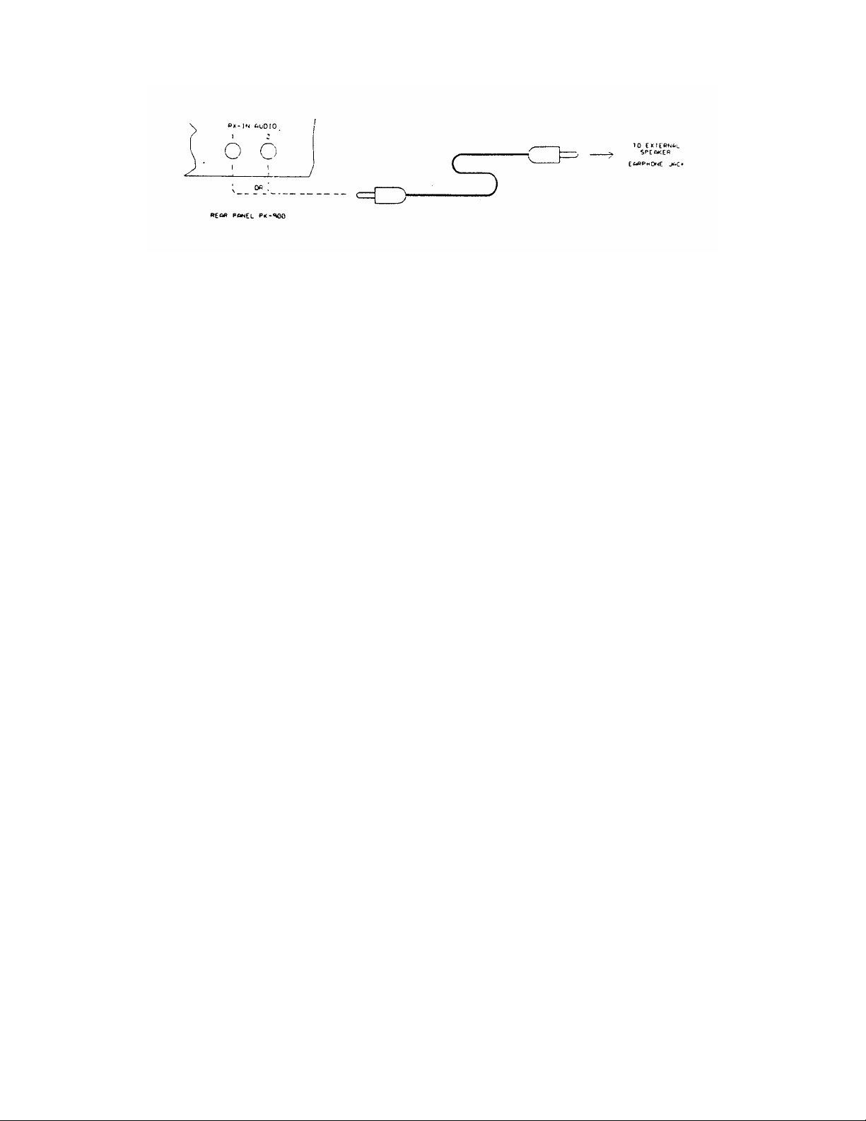
Figure 3-1 Receive audio connection to the PK-900.
If you are using an HF transceiver or Short-Wave receiver you should
consult Chapter 10 for information on the Signal Identification mode.
Chapters 4, 6, 7, 8 and 9 talk specifically about some of the modes
you may encounter on the HF and Short-Wave bands.
If you are connecting to a VHF scanner or VHF/UHF transceiver you
should look over Chapter 4 on VHF Packet operation.
3.3 Transmit and Receive Radio Connections
To connect your PK-900 to a HF or VHF/UHF TRANSCEIVER you will need
access to the Receive-Audio, Transmit-Audio (mic-audio), Push-To-Talk,
Ground and optionally a Squelch input for shared voice/data channels.
Most of these signals are typically available on the Mic connector and
also often on a rear-panel Accessory connector of the transceiver. If
you will be wiring the PK-900 to more than one radio, repeat the
procedures in section 3.3.5 for each radio you will connect.
3.3.1 Transceiver's Microphone or Accessory Connector?
The most convenient way to connect your transceiver is through a rear
panel Accessory connector if one is available. If the PK-900 is
connected as an accessory, the microphone used for voice operation can
sometimes be left connected to the transceiver. This makes changing
between voice and data modes easier than if the microphone must be
unplugged in order to connect the PK-900. On most HF radios
however, the mic is "hot" and should be unplugged during data
operation.
3.3.2 Connections for Specific Transceiver Models
APPENDIX E of this manual contains information and diagrams for
connecting the PK-900 to many modern HF and VHF transceivers.
Please turn to APPENDIX E and locate the transceiver model you will be
connecting to your PK-900. If you do not find the exact model of
your transceiver in APPENDIX E, then locate a model from the same
manufacturer that has the same Accessory or Microphone connector as
the unit you will be connecting.
1/93 3-2
Page 33
3.3.3 Check Your Transceiver's Operating Manual
Locate the Operating Manual for your transceiver and turn to the page
describing the connector to which you will attach your PK-900. Even
if you found the exact model of your transceiver in APPENDIX E, it is
a good idea to verify that your transceiver's manual agrees with the
information in the appendix. If the information does not agree, or
you could not find the exact transceiver model in APPENDIX E, then you
should use the information contained in your transceiver's manual to
connect the PK-900.
3.3.4 Specific Connection Points
Whether you are connecting an HF Single Side Band transceiver for
RTTY/FAX operation, or a VHF/UHF transceiver exclusively for packet,
the minimum connections to your transceiver will be almost identical.
HF transceivers have a few optional connections that will be covered
after the basic connections have been made.
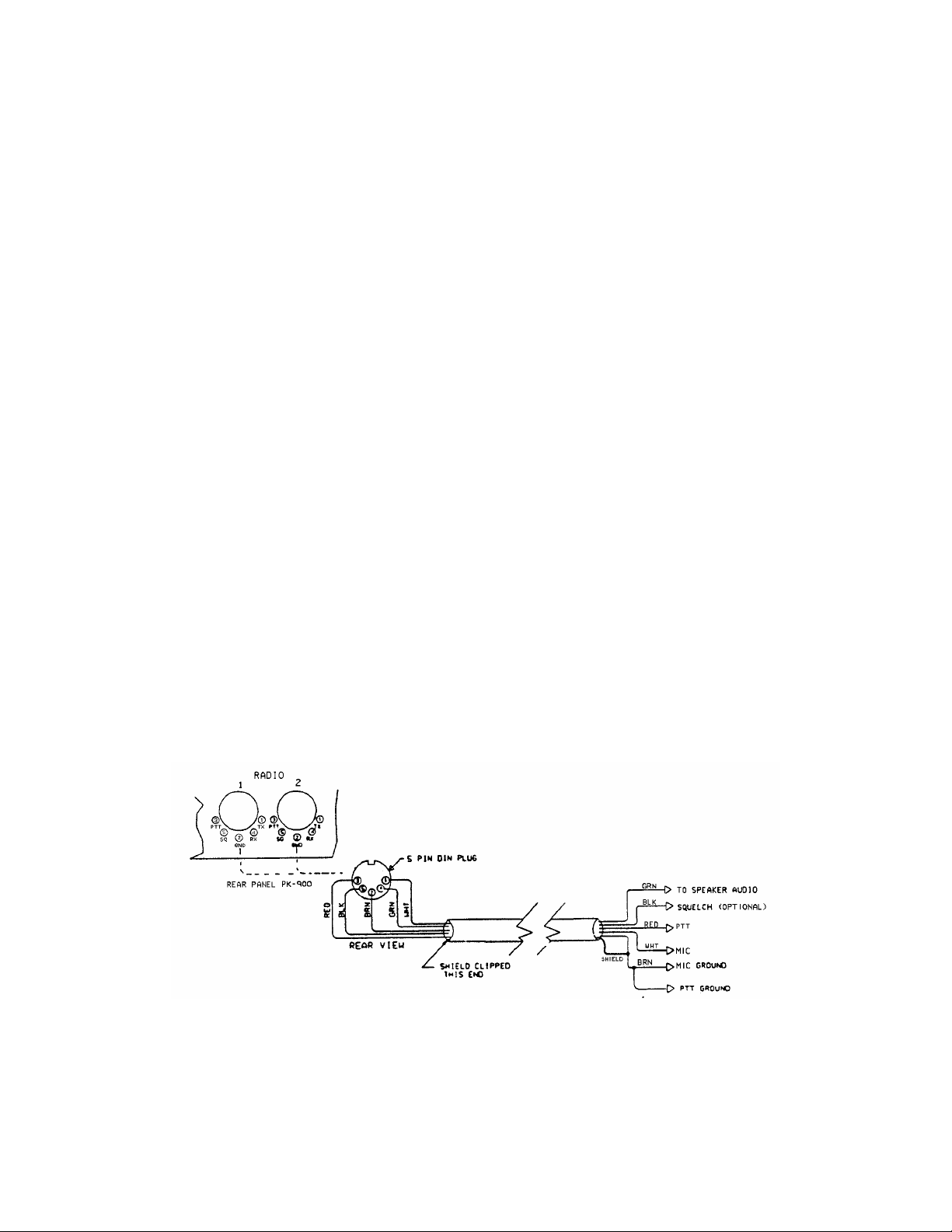
The following table and figure will be helpful in identifying the
proper basic connection points to the PK-900 radio cable.
_______________________________________________________________________________
Wire
Pin Signal Name Color Description
_______________________________________________________________________________
1 Microphone audio White AFSK from PK-900 to transceiver
2 Ground Brown Audio and PTT common return
3 Push-To-Talk Red PK-900 keys transmitter
4 Receive audio Green Audio from receiver to PK-900
5 Squelch Input Black Allows PK-900 to detect activity on a
shared mode channel (optional)
Shield/Drain Wire Silver Shield of cable / Microphone Ground
_______________________________________________________________________________
Table 3-1 Radio Port 1 and 2 Cable Connections
Figure 3-2 PK-900 to Radio Cable Connections
1/93 3-3
Page 34

3.3.5 Begin Assembling your Radio Cable
Assemble the tools, PK-900 Radio cable and connectors you will need
for each radio you wish to connect. You will probably also need a
small soldering iron (20-40 watts) and solder at your work area.
3.3.5.1 Prepare the Radio Cable
1. Locate one of the 5 ft PK-900 radio cables included with your
PK-900. Note that the Radio cables may have been shipped as a
single 10 ft cable which should be cut in half before use.
2. Prepare the bare end of one of the radio cables by removing an
appropriate amount of the jacket for the connector you will be
attaching. Usually this is 1/2 to 3/4 inch.
3. Carefully remove the foil shield exposing the colored wires
underneath. Be careful not to nick or cut the bare shield wire.
4. Strip back 1/8 inch of colored insulation from the GREEN, RED,
WHITE and BROWN wires.
NOTE: The BLACK wire is the squelch input and normally not used.
The black wire is only needed for Packet operation if the
channel you plan to operate on is used for both voice and
data. If you need this connection, strip away 1/8 inch of
BLACK insulation as done with the other four wires. If
this wire is not needed, then leave the insulation intact.
3.3.5.2 Verify the Connection Points with Your Manual
Look at the connector closely (with a magnifying glass if necessary)
and locate pin 1. Compare this to the location of pin 1 on the
connector drawing in your transceiver's manual and also in APPENDIX E.
This is important as some diagrams show the connector from the inside
of the transceiver, not the outside of the plug you are wiring. This
will help insure that the plug is not wired backwards.
3.3.5.3 Prepare the Connector
Now that the cable is prepared, you are ready to prepare the connector
for wiring. If the connector you are wiring has a shell, be sure that
it is placed over the cable before any connections are made. If this
is not done, an otherwise perfect wiring may have to be redone.
3.3.5.4 Wire the Connector
The following connections must be made for transmit and receive
operation of the PK-900. Refer to table 3-1 and figure 3-2 as well
as APPENDIX E and your transceiver's manual when making these
connections.
HINT: When wiring a Connector, it is often easier to wire the
inside or middle connections first and work your way to the
outside pins. For this reason the following steps are not
numbered and may be done in any convenient order.
1/93 3-4
Page 35

o Connect the Shield/Drain wire (Silver wire with no insulation) to
the Microphone GROUND connection if your transceiver has one.
If your transceiver does not have a separate Microphone or Audio in Ground connection, then this wire should connect to the single
Ground along with the Brown wire. See the next step.
o Connect the BROWN wire to the main GROUND on the connector. This
Ground is the one used for the PTT and receive audio. You should
connect the Silver Shield/Drain wire to this GROUND only if there
is not a separate Microphone Ground as described in the previous
step.
o Connect the RED wire to the Push-To-Talk (PTT) terminal on the
connector. At this time, check the manual to determine whether
your transceiver uses positive (+) or negative (-) PTT.
The PK-900 comes from the factory set for Positive PTT since
most transceivers use this method of keying. This will be
discussed in more detail in the Adjustment sections below. If
you are connecting a Handheld transceiver to your PK-900, you
will probably need a resistor and/or capacitor to isolate this
connection from the AFSK audio. Check APPENDIX E.
o Connect the WHITE wire to the MICROPHONE AUDIO terminal on the
connector. This connection carries the low level Audio Frequency
Shift Keying (AFSK) to the transmitter's microphone audio
section. If you are connecting a Handheld transceiver to your
PK-900, you will probably need a resistor and/or capacitor to
isolate this connection from the PTT. Check APPENDIX E.
o Connect the GREEN wire to the RECEIVER AUDIO terminal on the
connector. For the PK-900 to operate properly, we recommend at
least 200 mV RMS of receive audio be available. If you are
connecting to an Accessory Jack, make sure the available level is
at least 200 mV RMS. For CW work 400 mV may improve operation.
o If you will be using a Packet Radio channel that is shared with
voice users then you should connect the BLACK wire to the SQUELCH
status pin of the connector. This will prevent the PK-900 from
transmitting when there is a received signal strong enough to
open the Squelch. If you connect this pin you may have to change
the setting of the SQUELCH command in the PK-900. Most VHF/UHF
Packet channels are no longer shared with voice users so this
connection will probably not be needed.
This completes the minimum necessary connections for transmit and
receive operation with the PK-900. If you are interested in using
the PK-900 to transmit Morse code (CW) or transmit RTTY using FSK
inputs on your HF transceiver, the following three sections (3.3.6
and 3.3.7) should be read.
If you will not be using any of the connections described in the
following sections, then skip ahead to the Final Adjustment section
3.4 where you will set levels and prepare to go "On the Air".
1/93 3-5
Page 36
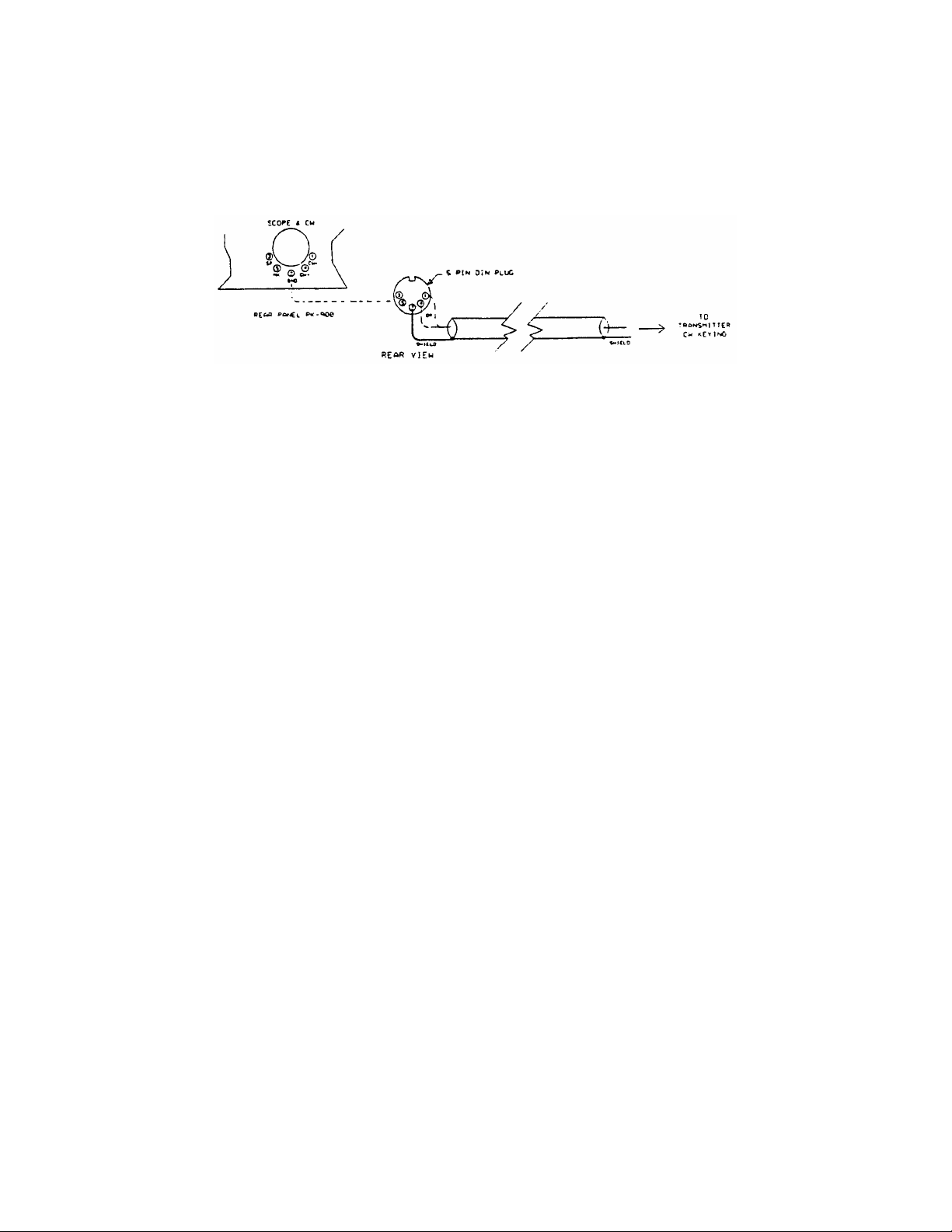
3.3.6 Wiring Your HF Transceiver for Direct CW Keying
The PK-900 can directly key CW with HF and VHF multi-mode
transceivers. This requires that a cable be wired from the CW KEY OUT
jack on the PK-900's rear panel to the CW keying input of your
transceiver on the correct Radio Port. Refer to the instructions
below and Figure 3-3 to wire the PK-900 side of the cable.
Figure 3-3: Direct CW Keying Cable diagram
1. Locate a 5 pin DIN connector from the PK-900's accessory bag.
2. Consult your radio's instruction manual to determine if your
radio uses negative (Grid Block) or positive keying polarity.
Locate some shielded audio cable from Radio Shack or other cable
house and solder the DIN connector to the cable as shown above.
3. Locate the connector for the CW keying input to your transceiver.
These are often supplied in your transceiver's accessory kit.
4. Wire the transceiver connector as per the instructions in your
transceiver's manual for a "Straight key".
Connect the shielded cable you just wired from the PK-900's positive
or negative keying output to your radio's CW key input connector.
See the Specifications on page 1-4 for maximum limits.
3.3.7 Connections for Direct FSK Operation on RTTY
Some HF SSB radios provide direct FSK (Frequency-Shift Keying) for
RTTY operation. Direct FSK can be an advantage when using RTTY and
AMTOR and can sometimes help in HF packet operation. FSK operation
may be helpful if your transceiver can switch in filters. Be cautious
of narrow filters as they can limit your data rate. Direct FSK is not
always recommended for data speeds above 110 bauds. Consult your
transceiver's manual for further recommendations on direct FSK.
To install and operate your PK-900 and radio in the FSK mode:
1. Connect a shielded cable from the PK-900's FSK receptacle,
pins 1 or 4, to the radio's FSK input for radio port 1. Pins 3
or 5 are the FSK outputs for radio port 2.
NOTE: Polarity of the FSK signals is not standardized by the radio
manufacturers. We have observed that Icom radios most often
use FSKN (pins 3 and 4), while Kenwood radios most often use
FSKR (pins 1 and 5). Consult your transceiver's manual to
identify the proper polarity.
1/93 3-6
Page 37
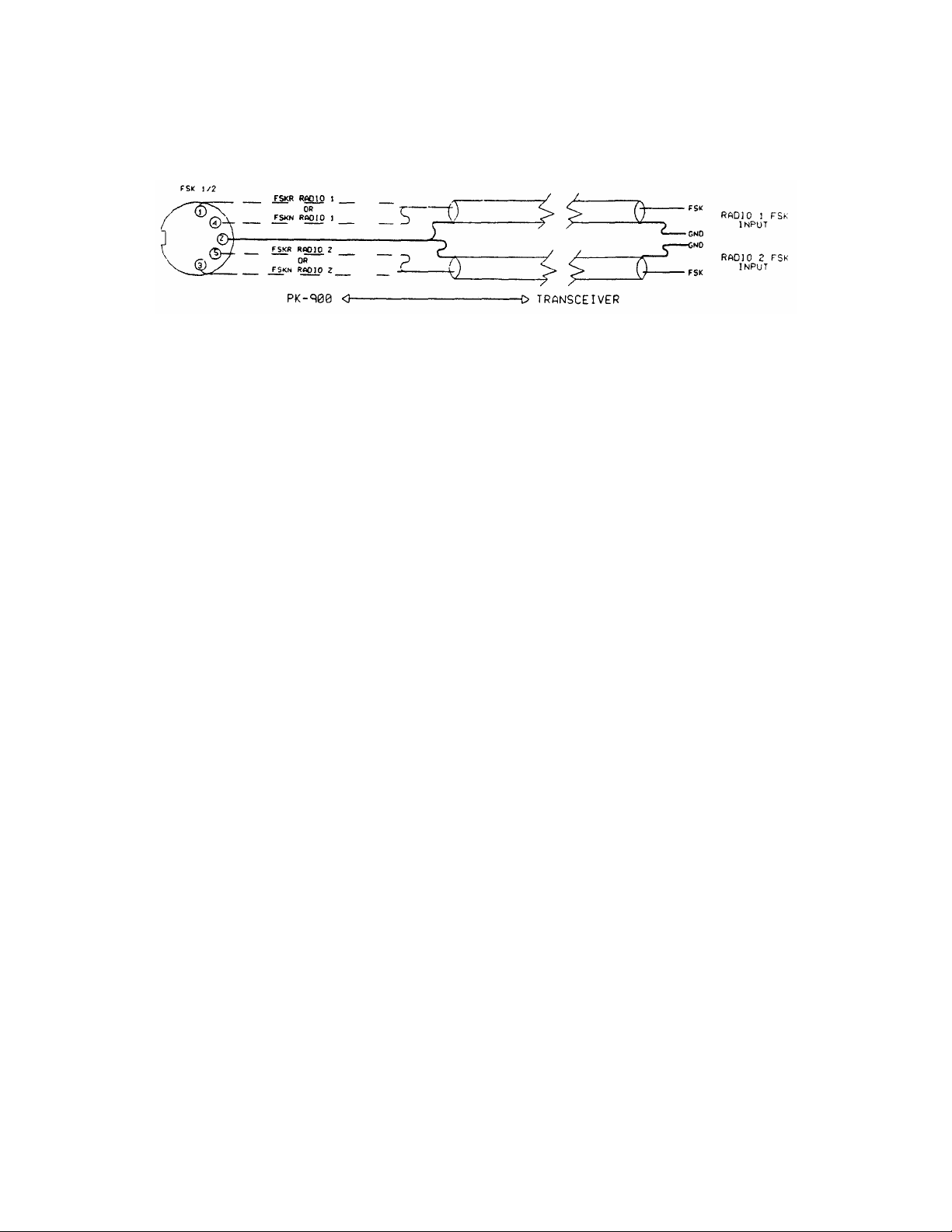
2. Connect the FSK lines from the PK-900 to your radio's FSK or
RTTY input in accordance with your radio's requirements.
See Figure 3-4 below.
Figure 3-4 FSK Connector Connections
NOTE: When using FSK, the same power and duty cycle limits apply
as cited earlier for AFSK operation. Consult your radio's
operating manual for any power or transmit time limits.
3.4 PK-900 Configuration Jumpers and Connections
Before operating the PK-900, you must first make sure it is
correctly configured for your radio's PTT. After this has been
checked you should then connect the cables you constructed above.
3.4.1 Push-To-Talk (PTT) Configuration
Before you connect the radio cable(s) you just made to the
PK-900, consult your transceiver's manual for Push-To-Talk keying
polarity. Most transmitters and transceivers made in the last 15
years use Positive PTT keying. However some gear, especially if it
contains vacuum tubes, may use a negative PTT keying voltage.
The PK-900 is configured for positive PTT at the factory so it will
operate with most equipment without changes. However, if necessary,
you can change the polarity of the PTT configuration on either Port 1
or Port 2. Follow these steps:
o Remove four screws from the top of the PK-900 chassis cover and
lift off the cover.
o Locate Jumper posts JMP1 and JMP2 which are about 4 inches in
from the right-rear corner of the PCB.
o JMP1 configures Port 2 and JMP2 configures Port 1.
o When the shorting jumpers are towards the fuse, the port is
configured for Positive (+) PTT. When the shorting jumpers are
towards the center, the port is configured for Negative (-) PTT.
Replace the cover and four screws when you are finished configuring
the polarity of the PK-900 PTT circuit.
1/93 3-7
Page 38
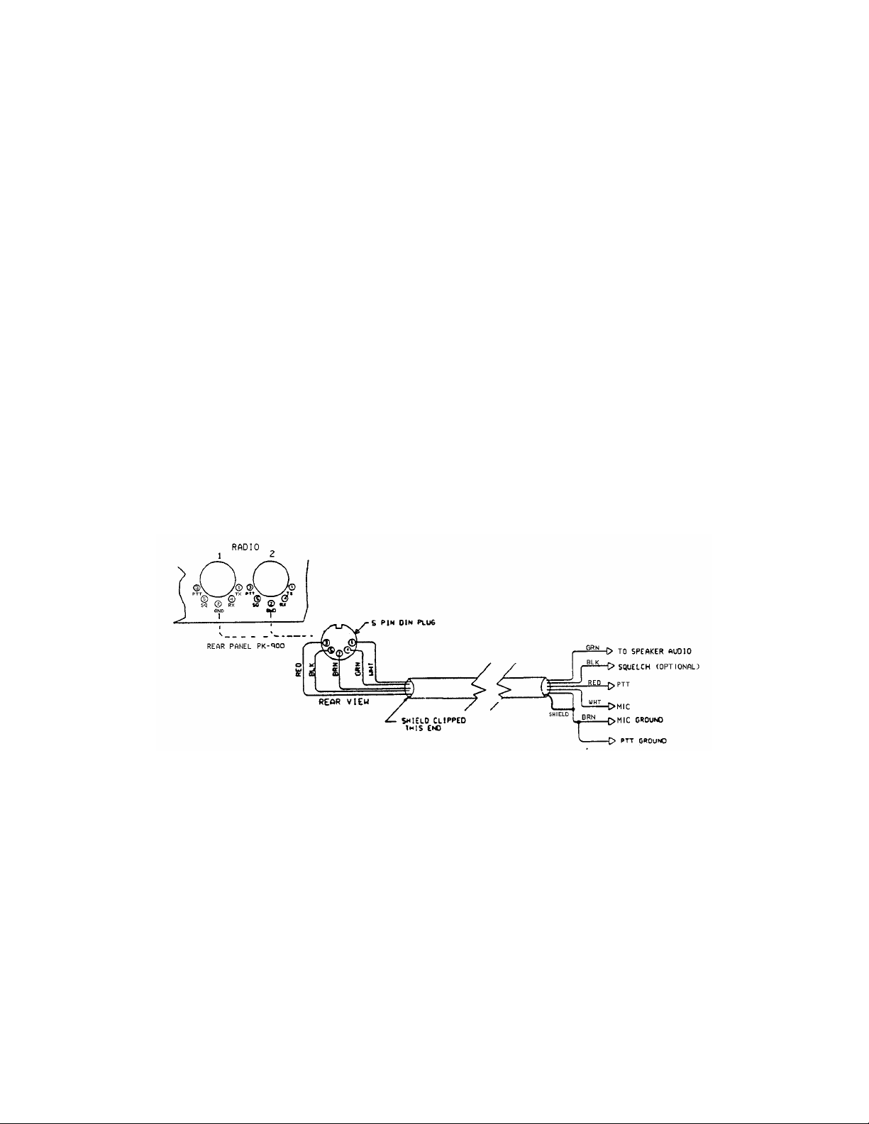
3.4.2 PK-900 Connections
Remove power from the PK-900, your transceiver and all accessories
before making any connections.
Connect the radio cable(s) you constructed in section 3.3.5 between a
Radio port on the PK-900 and your transceiver(s).
If you wired cables for CW keying or Direct FSK then connect these to
the appropriate point on your equipment.
3.5 Transceiver Adjustments
This section is split into separate procedures for FM and SSB radios.
You may adjust either port at any time without affecting the other.
3.5.1 FM Transceiver Final Adjustments
1. Turn on your computer and PK-900 and start your terminal
program.
2. Connect the radio to a dummy load. Be prepared to monitor your
transmissions with another nearby radio such as a handheld
transceiver.
3. Verify that your PK-900 and FM radio are connected as shown in
Figure 3-5 below.
Figure 3-5 Radio-to-PK-900 Connections
4. If you are using an AEA program such as PC-PAKRATT II or MACRATT,
you must enter the Dumb Terminal mode to access the CALIBRATE
Mode as described below.
5. Enter the Calibrate mode by typing: "CAL <Enter>."
NOTE: In the Calibrate mode only, the "K" key toggles the
transmitter PTT line on and off. The "SPACE BAR" toggles
the PK-900's tone generator from "Mark" (the lower pitched
tone) to "Space" (the higher pitched tone). The PK-900
has a transmit watchdog timer circuit that unkeys your
transmitter automatically after sixty (60) seconds. As you
perform the following adjustments, unkey periodically, then
rekey the transmitter by typing "K."
1/93 3-8
Page 39
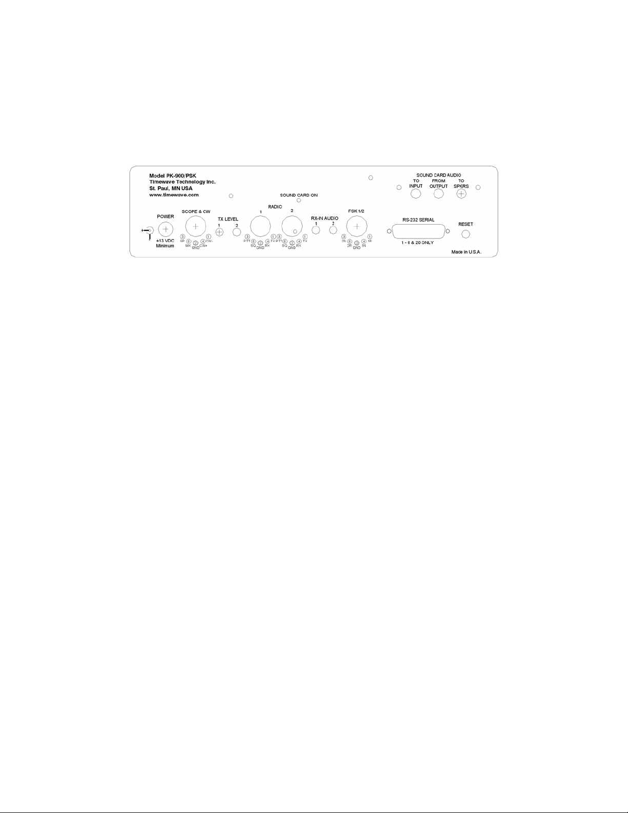
6. Press the "K" key on the keyboard to key the transmitter. You
should hear a continuous tone in the monitor receiver.
7. Tap the space bar several times until the higher pitched of the
two tones ("Space") is heard.
8. Refer to the figure below of the PK-900's rear panel and locate
the AFSK TX level potentiometer adjustment for the radio port you
are calibrating.
Figure 3-6 PK-900 Rear Panel AFSK TX level Controls
9. With the PK-900 keying the transmitter and sending the higher
of the two tones, adjust the transmit audio level for the port
you are calibrating as follows:
o Listen to the monitor receiver; turn the PK-900's rear panel AFSK Output Level adjustment screw clockwise (CW)
until you hear no increase in output level in the receiver.
o Rotate the AFSK Output Level adjustment screw
counterclockwise (CCW) until the audio signal on the
monitoring receiver is slightly but noticeably reduced from
the maximum level. This is the proper AFSK level setting.
NOTE: If you find the "correct" AFSK level setting occurs in the
first 20% of the potentiometers range, the adjustment may
be difficult. If you find this adjustment difficult, the
internal AFSK level jumper may be moved to the LOW setting
which will improve the adjustment range of the potentiometer.
To locate the internal AFSK level jumpers in the PK-900,
remove the four screws that secure the top chassis, and
carefully remove it by lifting straight up.
Look for jumpers JP5 and JP6 near the radio port connectors
at the rear of the PK-900 as shown in figure 3-7 below.
Jumper JP6 controls the output level of radio port 1, and
jumper JP5 controls the output level of port 2. When the
jumper is towards the front, the output level is HIGH.
Move the jumper for the radio port being adjusted to the
rear two pins to set the AFSK output level to LOWer range.
Repeat step 9 when this has been completed.
4/94 3-9
Page 40
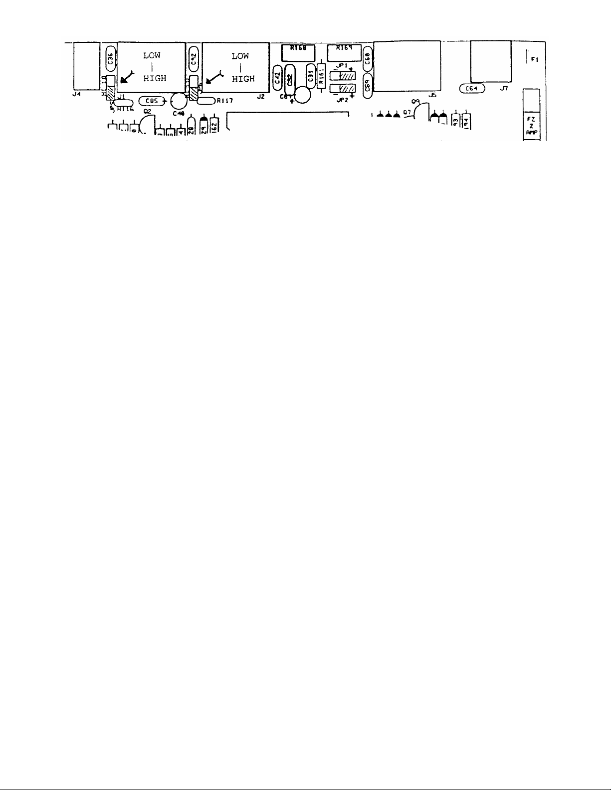
Figure 3-7 PK-900 AFSK HI/LOW Level Jumpers
10. Type "K" to return to receive mode.
11. Type "Q" to "Quit" (exit) the calibration routine.
You've now set your FM transmitter's deviation to an approximate
level which will be adequate for operation.
12. With your radio in the receive mode, open the squelch control so
that a steady hiss or noise is heard on a speaker.
13. If using radio port 1, set the receiver's volume control to a
comfortable listening level. With the receiver unsquelched but
with no signal present, adjust the THRESHOLD control so the DCD
LCD on your PK-900 just lights. This is the approximate proper
level for best receive performance from your PK-900's modem. If
using radio port 2. Normal listening levels will activate the
DCD with received signals.
14. Reset your receiver's squelch control for normal operation.
3.5.2 SSB Transceiver Final Adjustments
Digital modes with an SSB radio require some different settings of
the radio's operating controls for proper AMTOR and packet operation.
Be sure to observe the following setting recommendations:
o Set VOX to OFF.
o Set speech compression to OFF.
o Set AGC to FAST (if available).
o If you wish to use an external RF amplifier in AMTOR, PACTOR or
Packet, disconnect the ALC cables between your SSB radio and the
external RF amplifier.
Remember - Baudot and ASCII RTTY and Mode B (FEC) AMTOR are
continuous key-down conditions - Your radio's duty cycle is 100% for
the duration of each transmission. If your SSB radio isn't designed
for continuous full-power operation, you must operate your radio at
reduced output power. Consult the manufacturer's specifications for
details on the operating duty cycle.
NOTE: Make all connections with all power off.
4/94 3-10
Page 41

1. Connect your PK-900 and SSB radio as shown in Figure 3-5.
2. Turn on your PK-900 and your computer and start your terminal
program.
3. Connect your SSB radio to a dummy load.
4. If your SSB radio has a "monitor" facility, i.e., an audio
output that lets you listen to the audio signals entering the
microphone or phone patch jacks, turn that monitor circuit on.
5. Set the radio's MODE selector to LSB (lower sideband).
6. Set the radio's meter switch to the "ALC" position. If the
radio doesn't have an "ALC" indication, set the meter switch to
"Ip" or "Ic" to read plate/collector current. If a current
reading isn't available, set the meter to indicate power output.
7. If you are using an AEA program such as PC-PAKRATT, COM-PAKRATT
or MACRATT, you must enter the Dumb-Terminal mode (see program
manual) to access the CALIBRATE Mode described below.
8. Enter the Calibrate mode by typing: "CAL <Enter>."
NOTE: In the Calibrate mode only, the "K" key toggles the
transmitter PTT line on and off. The "SPACE BAR" toggles
the PK-900's tone generator from "Mark" (the lower pitched
tone) to "Space" (the higher pitched tone). The PK-900
has a transmit watchdog timer circuit that unkeys your
transmitter automatically after sixty (60) seconds. As you
perform the following adjustments, unkey periodically, then
rekey the transmitter by typing "K."
9. Adjust the transceiver's Microphone Gain control to its minimum
setting.
10. Press the "K" key on the keyboard to key the transmitter.
Increase the transceiver's microphone gain control until you hear
a continuous tone in the radio's monitor output.
11. If you are able to hear the tones in radio's speaker, tap the
space bar several times until you hear the lower pitched of the
two tones ("Mark").
12. With the PK-900 keying the transmitter and transmitting the
lower of the two tones, adjust the transmit audio level as
follows:
I. Rotate the microphone gain control clockwise (CW)
approximately in the one-quarter ON position. You may
also set it to the position used for SSB operation.
II. Turn the PK-900's rear-panel AFSK Output Level
adjustment screw clockwise (CW) until the ALC
meter shows a small deflection from the unmodulated
reading. Check the radio's plate/collector current
or output power indicators.
4/94 3-11
Page 42
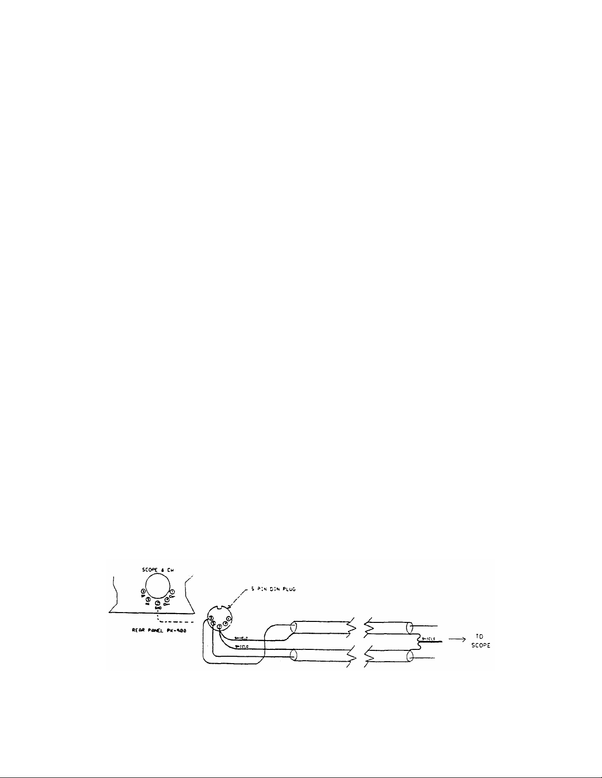
III. Adjust the AFSK Output Level control until the radio's
indicators show approximately thirty percent (35%) of
the manufacturer's rated full-power reading.
EXAMPLE: If the manufacturer's plate/collector current
specification for CW operation is 200 mA, set the AFSK
Output Level control and your microphone gain control
so that the plate/collector current indicates 75 mA.
IV. Your radio may be able to operate at higher output
levels. Consult your radio manual.
NOTE: If you find the "correct" AFSK level setting occurs in the
first 20% of the potentiometers range, the adjustment may
be difficult. If you find this adjustment difficult, see
the NOTE in step 9 of the FM adjustment section on page 3-9
of this manual. Repeat step 12 when this has been competed.
13. Type "K" to return to receive mode.
14. Type "Q" to "Quit" (exit) the calibration routine.
You have now set the PK-900's transmit audio output level and
your SSB radio's microphone gain control to an approximately
correct level for all operating modes.
NOTE: For packet radio operation, the radio's microphone gain
control can be adjusted to produce the full output power
recommended by the radio manufacturer. Packet is a "bursty"
mode and the transmitter is keyed on and off automatically
by the PK-900. The resulting duty cycle is much less than
100% and full-power operation is generally acceptable.
15. With your radio in receive mode, tune the receiver to a clear,
unoccupied frequency.
16. Set the receiver's audio volume control (AF GAIN) to the position
you would normally use for CW reception. This is the approximate
receiver audio output level for best receive performance from
your PK-900's modem.
3.6 Oscilloscope Connections
Some operators prefer to use an oscilloscope for tuning. Radio
port 1 provides mark and space outputs for driving the vertical and
horizontal inputs of an oscilloscope as shown below.
Figure 3-8 PK-900 Oscilloscope Connections
4/94 3-12
Page 43

CHAPTER 4
PACKET RADIO
4.1 Overview
In the last several years Packet has grown to become perhaps the most
popular digital mode on the amateur bands. Although Packet can be
found on HF (primarily on the 20 meter band) it is most popular on the
VHF and UHF FM bands. This chapter will start with general Packet
operation and then discuss VHF and UHF Packet. Packet on the HF bands
requires some special considerations, so we will leave it until the
end of this chapter.
Your PK-900 can operate HF or VHF Packet (on Radio port 2) and any
other digital mode on Radio port 1 at the same time. This feature can
come in handy allowing you to keep an "ear" on local packet activity
while operating on any of the other digital modes normally found on
HF. Sorting out the data from both Radio ports also requires some
special considerations and will be discussed later in the chapter
after HF Packet operation has been covered.
4.1.1 Getting Started
You can learn quite a bit about Packet operation with the
PK-900 before even connecting it to a transceiver. For your first
packet practice, the PK-900 will be connected in a "loopback"
circuit as done in the "Quick Check" performed in Chapter 2. In this
configuration, the PK-900 will "talk to itself" which allows you to
become familiar with packet before actually going on the air.
4.1.2 Making the Loopback Connection
Make sure the PK-900 is turned OFF and power is removed before
performing one of the following.
I Locate the WIRE "Loop-back" jumper and insert it into pins
1 and 4 of the RADIO-1 connector on the PK-900 rear panel.
II If you cannot locate the wire "Loop-back" jumper and have a
spare Radio cable, you may construct the following:
1. Get the unused Radio Cable mentioned in Chapter 3.
2. Strip about 1/4 inch of insulation from the Green and White
wires at the "radio" end of the cable.
3. Join the Green and White wires by twisting them together
gently.
4. Insert the 5-pin DIN connector end of the cable into the
"RADIO-1" connector on the PK-900's rear panel.
5. Go on to section 4.2.
1/93 4-1
Page 44

4.2 Packet Introduction
You've now connected your PK-900's transmit audio output to its
receive audio input. Your PK-900 can now "talk to itself" in
packet.
1. Set the rear-panel AFSK level control for RADIO-1 at 50%
(straight up and down) for the following Packet introduction.
NOTE: If you have adjusted the RADIO-1 rear-panel AFSK level
control for a particular transceiver in chapter 3, then mark
this setting with a pencil so it can be reset when finished.
2. Turn on your computer. Load and run your communications program.
If you are using an AEA PAKRATT Program, follow the program
manual's instructions to enter the Packet mode on Radio Port 1,
and then skip to step 4.
If you are using another Computer program or a Terminal, set the
communication parameters as done in Chapters 2 and 3.
3. Press the PK-900's front panel power switch to the ON position
if you have not already done so.
You should notice the sign-on message seen in chapter 2. The LCD
Status display should indicate you are in the Packet mode.
4. After you have seen the sign-on message and/or entered the Packet
mode, you must enter your own callsign (with the MYCALL Command)
if you are to converse with any other Packet stations. If you
try to connect to a station without entering your call sign, your
PK-900 will send you the following message:
?need MYcall
If you are an SWL and do not intend to transmit, you should enter
"AAA" as a Callsign (MYCALL).
If you are using an AEA PAKRATT program, follow the instructions
in the Program Manual to enter your callsign. If you are using a
terminal or terminal emulating program on your computer, you must
use the MYCALL command to install your call sign.
Note that since the PK-900 has two radio ports, you must enter
a callsign for each port. The callsigns may be the same, or can
be different to make life a little easier in the "two Ham"
family. You must change the callsign from the default "PK900"
on each radio port, or that port will not transmit packets. For
example, if your Callsign is WX2BBB, enter the following:
cmd:MYCALL WX2BBB/WX2BBB <Enter>
The PK-900 will respond with:
MYcall was PK900/PK900
MYcall now WX2BBB/WX2BBB
1/93 4-2
Page 45

Both Packet radio ports will now assume the callsign WX2BBB.
5. If you are using an AEA program follow the instructions in the
Program manual to CONNECT in packet mode to your own callsign
(the one you just entered in MYCALL).
If you are using a Computer Terminal or a non-AEA program,
entering the following after the "cmd:" command mode prompt will
cause the PK-900 to Connect to yourself:
CONNECT (your callsign) <Enter>
After pressing <Enter>, you should observe the RADIO 1 TX LCD
and DCD LCD light briefly, and the TUNING bar graph
spread.
After a few moments, your monitor should display:
*** CONNECTED to (your callsign)
Notice that the front panel RADIO 1 Connect LCD shows CONNECTED.
You may also notice that the CONVERSE LCD is also on
indicating that the PK-900 is ready to CONVERSE with the
station (in this case it is yourself).
This is how a packet connection is established. Whether you
are "Connecting" to another Amateur, a Packet Bulletin Board
System (PBBS) or a Networking Switch (more on this later)
this initial procedure must be used to establish each and
every Connection.
6. Type a few characters to yourself such as "Hello this is my first
packet Connect. My name is ..." then press the <Enter> key.
Shortly after pressing the <Enter> key, you should see the
message you typed reappear on your screen. If you had connected
to a distant station, they would have seen the message you typed
appear at nearly the same time.
7. After you have typed a few lines (packets) to yourself, you will
probably want to end the connection or "DISCONNECT".
If you are using an AEA program, follow the instructions to
DISCONNECT from the packet station you are talking to.
If you are using a Computer Terminal or a non-AEA terminal
program, the following will cause the PK-900 to DISCONNECT:
Enter <CONTROL-C> (hold down the Ctrl and then type the letter C).
Your monitor should respond with the command prompt:
cmd:
Enter the following: D <Enter>.
Your monitor should respond with:
cmd:*** DISCONNECTED: (your callsign)
p1 (your call)*>(your call) (UA)
1/93 4-3
Page 46

Note that the front panel CONNECT LCD will change to
DISCONNECTED indicating that you are no longer connected.
8. You have just done the three things necessary in any Packet QSO.
o You started the QSO (with yourself) by CONNECTing. (Step 5)
o You sent some information (to yourself) and then received
the information that you sent. (Step 6)
o You then ended the QSO by DISCONNEcting. (Step 7)
Repeat steps 5, 6 and 7 above until you feel comfortable with
Connecting, exchanging information and Disconnecting. These
operations will be performed each time you use Packet so they
should be second nature to you before going on the air.
When you feel comfortable Connecting, sending information and
Disconnecting, you are ready to start listening to VHF packet.
9. Turn OFF and remove power from the PK-900.
o Return the Port 1 rear-panel AFSK level potentiometer to
the setting you marked in Step 1, if any.
o Remove the "Loop-back" jumper from the RADIO-1 port and
reconnect your transceiver or receiver set-up in Chapter 3.
4.3 VHF/UHF Packet Operation
We will first listen to (and watch) some of the VHF or UHF Packet
activity in your Local Area. This will allow you to become a little
better acquainted with packet in your area before going "On The Air".
1. Construct a Radio Cable for the VHF/UHF transceiver you intend to
use for Packet as described in Chapter 3 and connect your
transceiver to the RADIO-1 connector on the PK-900 rear panel.
2. Load and run your communications program and enter the Packet
Mode as done in the Packet Introduction section above.
3. Set Radio Port 1 for VHF Packet operation (default) as follows.
If you are using an AEA program, follow the instructions to
select the VHF modem on Port 1 by turning the VHF Parameter ON,
this will automatically set the radio baud rate HBAUD to 1200.
If you are using a Computer Terminal or a non-AEA terminal
program, the following sets the VHF mode of the PK-900:
Type <CONTROL-C>. (Type C while pressing the <Ctrl> key down.)
Your monitor should respond with the command prompt:
cmd:
Then enter VHF ON <Enter>
Your monitor should respond with:
1/93 4-4
Page 47

Vhf was OFF/ON
Vhf now ON/ON
Then enter HB 1200 <Enter>
Your monitor should respond with:
HB was 300/1200
HB now 1200/1200
4. Turn ON your VHF or UHF FM transceiver and tune to a known packet
channel in your area. Most packet operation is on simplex, so
the repeater offset on your transceiver should be disabled.
If you know there is packet in your area, but do not know the
frequency, you should try some of the following frequencies:
2 meter (144 MHz) band:
145.01 MHz, 145.03 MHz, 145.05 MHz, 145.07 MHz, 145.09 MHz
144.99 MHz, 144.97 MHz, 144.95 MHz, 144.93 MHz, 144.91 MHz
1-1/4 meter (220 MHz) band:
223.40 MHz, 223.42 MHz, 223.44 MHz, 223.46 MHz, 223.48 MHz
70 cm (440 MHz) band:
440.975 MHz, 441.000 MHz, 441.050 MHz, 441.025 MHz, 441.075 MHz
You know you've found a packet channel when you hear the
characteristic "Braaaaaap" sound of packet transmissions.
5. Once you've found an active packet channel, you must make sure
you have enough receive audio (volume) from your transceiver to
light the DCD LCD on the PK-900 when a packet is being
received. If the DCD LCD does not light when packets are
received, either there is not enough receiver audio or the
Threshold control is turned too far counter clockwise.
You must also make sure that the DCD LCD goes out when no packet
signals are present on the channel. If the DCD LCD does not go
out when the channel is clear, make sure the Squelch control on
your transceiver is set high enough to silence the speaker. If
the DCD LCD stays on when the packet channel is quiet, your
PK-900 will not send packets to other stations.
1/93 4-5
Page 48

4.3.1 What You Should See
If all is operating properly, you should see some packets on your
screen. Some typical packets you might "Monitor" are shown below:
p1 N7ALW*>WA7GCI [C]
p1 WA7GCI*>N7ALW (UA)
p1 K6RFK>N7ALW*>N7GMF:
Goodnight John, its been nice talking to you.
p1 N7ALW*>WA7GCI:
Hi Bob, how are you this evening?
p1 KD7NM*>MAIL:
Mail for: K6RFK N7ML
p1 N7HWD-8*>ID:
NET/ROM 1.3 (SEA)
p1 SEA*>N7ML:
SEA:N7HWD-8> Connected to #SEA:N7HWD-7
p1 K6RFK>N7ALW*>N7GMF [D]
N7GMF>N7ALW*>K6RFK (UA)
NOTE: You will probably see data (Packets) on the tuning bar-graph
which do not print on the screen. This is normal and is a
function of the MONITOR and the MPROTO commands.
4.3.2 What It Means
There are different types of packets that mean different things to the
PK-900. Your PK-900 keeps track of and knows what to do with the
packets so users need not be concerned with them most of the time.
Since the PK-900 can "Monitor" all Packet activity on a channel,
we'll briefly discuss the types of packets you will most often see.
Skip to the next section if you do not plan on doing much monitoring.
Let's look at the first packet in the examples above and get
acquainted with what it all means.
p1 N7ALW*>WA7GCI [C]
The first two characters in monitored packets represents which radio
port "heard" the packet and will be either "p1" or "p2". Every single
packet you send will have your callsign (the one you just entered in
MYCALL) as the first callsign of the packet. The callsign after the
">" is the next station the packet will go to. So the packet listed
above originates from N7ALW and is being sent to WA7GCI. All packets
will have at least these two callsign fields.
The "[C]" immediately following the two callsigns identifies this
packet as a CONNECT Request. So we see that N7ALW is requesting a
packet CONNECTION with WA7GCI.
1/93 4-6
Page 49

The second packet in the above examples is a response to the first.
p1 WA7GCI*>N7ALW (UA)
In this case we see that WA7GCI is sending to N7ALW by the order of
the callsigns. This packet acknowledges the Connect request as shown
by the "(UA)" which stands for Un-numbered Acknowledge.
One benefit of packet radio is that packets can be relayed or
"digipeated" by stations on the same frequency. In fact, packets can
be relayed by up to eight stations to reach a distant station that
cannot be heard directly. In practice, digipeating through many
stations does not work very well, but you will often see packets
digipeating through one or two stations to reach their destination.
The packet shown below is an example of a digipeated packet.
p1 K6RFK>N7ALW*>N7GMF:
Goodnight John, its been nice talking to you.
This packet originated from K6RFK and is being sent to N7GMF but is
"Digipeated" through the station N7ALW. We also see that this packet
contains data by the text "Goodnight John...". Another thing that
should be noticed in this packet is the asterisk (*) in the first
line. The asterisk tells which station was actually heard sending the
packet. In this case, we can see that we actually heard the
digipeating radio station N7ALW. Without the asterisk, we could not
tell whether the transmission came from radio station K6RFK or N7ALW.
More will be discussed about digipeating later, but the above example
is typical.
The following packet is a data packet from N7ALW to WA7GCI.
p1 N7ALW*>WA7GCI:
Hi Bob, how are you this evening?
Remember that in the first example we saw the two stations Connect.
Now that they are connected, they may exchange data packets.
The following packet is a Beacon packet from KD7NM. Since we see the
packet is addressed to "MAIL" we know KD7NM is probably a Packet
Bulletin Board System (PBBS).
p1 KD7NM*>MAIL:
Mail for: K6RFK N7ML
The data section of this packet says "Mail for: K6RFK N7ML". This
Beacon lets people know that K6RFK and N7ML have mail waiting on the
KD7NM PBBS without having to connect.
1/93 4-7
Page 50

The following Beacon packet is intended as identification for a
NET/ROM level-3 packet networking switch.
p1 N7HWD-8*>ID:
NET/ROM 1.3 (SEA)
In this case, the Packet Switch is using the callsign N7HWD-8, but
also uses the alias SEA as a callsign. There are many types of Packet
Switches now in use, but NET/ROM is one of the most popular. We will
briefly discuss using a NET/ROM switch later in this chapter since
most switches operate in much the same way.
The packet below was sent by the network switch SEA to N7ML.
p1 SEA*>N7ML:
SEA:N7HWD-8> Connected to #SEA:N7HWD-7
The packet above from SEA contains the data "SEA:N7HWD-8> Connected to
#SEA:N7HWD-7". This message tells N7ML that he is now connected to
another port on the SEA Node named #SEA. Again, we will talk more
about how and why N7ML might want to do this later in the chapter.
The following packet is again from K6RFK to N7GMF and is being
digipeated through N7ALW. This packet indicates that K6RFK is
finished talking to N7GMF and wants to Disconnect. Again we see that
we are not hearing K6RFK, rather we are hearing N7ALW as indicated by
the asterisk (*) after the callsign.
p1 K6RFK>N7ALW*>N7GMF [D]
The following packet is an acknowledgment (or simply called an ACK)
that lets K6RFK know that N7GMF has acknowledged the Disconnect
request sent above. K6RFK and N7GMF are no longer Connected.
p1 N7GMF>N7ALW*>K6RFK (UA)
As can be seen, all of the above examples were heard on radio port 1
of the PK-900. If a second radio was connected to radio port 2,
we would have seen some monitored packets prefaced with a "p2" as
well. See section 4.8 for more information on controlling both
radio ports when you are ready.
NOTE: Some applications software such as PB and PG for Amateur
Satellite use have problems with the port designators "p1" and
"p2" in front of monitored packets. To disable the port
designators "p1" and "p2" from appearing turn OFF User Bit 19
(UBIT 19) by typing "UBIT 19 OFF <Enter>" at the command
prompt.
1/93 4-8
Page 51

4.3.3 What Happens When You Connect
If you are working with a friend who is familiar with packet, you may
want to skip to section 4.4. If you are on your own, the following
three sections will help you learn what to expect on VHF/UHF packet.
There are three different kinds of packet stations you are likely to
encounter in your first Connects: Standard TNCs, Mailbox Systems and
Network Switches. The following sections discuss each station type.
4.3.3.1 Standard TNCs
When you first turn on your PK-900, it becomes a standard AX.25
packet TNC (Terminal Node Controller). All TNCs and Multimode
controllers have this capability. When you Connect to a TNC, in most
cases you will be connecting directly to someone's computer screen.
If you see an automatic Connect Message (CMSG) similar to the one
below, you know you have reached a TNC.
Welcome to my packet station. If I don't respond, please
leave a message and Disconnect.
If you get a message like this when you connect to another station,
usually you would type something like "Are you there?". If you do not
see a response from the other station in a minute or so, simply leave
a message - just like a telephone answering machine.
The TNC at the other station should then hold your message until the
operator returns to his computer. Later we will discuss how your
PK-900 can do the same for messages it receives from others.
4.3.3.2 Mailbox Message Systems
Although Standard TNCs allow incoming messages to be saved, there is
no way for the owner to leave a message for someone who will connect
at a future time. The ability to both send and receive messages
without the owner being present is accomplished by a Mailbox.
There are many different Packet Mailbox systems in use. Some systems
are large and require the use of a dedicated computer. Other systems
are small like the personal MailDrop built into your PK-900.
Large systems are often called Packet Bulletin Board Systems (PBBS)
since they serve as electronic message centers for a local area.
PBBS's are a source of information as well as a gateway for messages
that can be sent to and received from other parts of the country or
world. You will probably want to locate the local area PBBS nearest
you and connect to it from time to time.
Mailbox systems are easy to use and most operate in much the same way.
Most Mailboxes and other automatic systems usually have Help available
by sending an "H" or "?". If you connect to a Mailbox such as a
PK-900 MailDrop you will see something like the following:
*** CONNECTED to KD7NM
[AEA PK-900] 17480 free (A,B,H,J,K,L,R,S,V,?) >
1/93 4-9
Page 52

If you get something like this when you connect to another station,
try typing an "H" or a "?" to get a help list as shown below:
A(bort) Stop Read or List
B(ye) Log off
H(elp) Display this message
J(log) Display stations heard
K(ill) K n: Kill message number n
KM : Kill messages you have read
L(ist) L : List message titles
LM : List messages to you
R(ead) R n: Read message number n
RM : Read all your unread messages
S(end) S : Send a message to SYSOP
S n: Send a message to station n
? Same as H(elp)
[AEA PK-900] 17480 free (A,B,H,J,K,L,R,S,V,?) >
There are quite a few options available on the MailDrop, but the most
commonly used commands are L(ist), R(ead), S(end) and K(ill) message.
For example, you may first want to LIST all the messages that are
available on a mailbox that you connect to. This is done by simply
sending "L" or "LIST" command to the system you have just connected.
If you are interested in any of the message subjects that appear, you
may then READ the messages that interest you. To read a message,
simply send the command "R (message number)", where (message number)
is the number of the message you are interested in.
After you are finished reading messages, you may want to SEND a
message to the SYSOP (short for System Operator) or to another user.
To send a message simply enter "S (callsign)" where (callsign) is the
call of the station you are sending the message to.
When you are finished Listing, Reading and Sending messages, you will
want to send the Bye command to log-off (disconnect) from the Mailbox.
Feel free to experiment with Mailboxes and other packet systems.
Remember that most automatic systems will send you help on commands if
you send an "H" or "?". For more information on setting up and using
your own PK-900 Maildrop, see Chapter 5 on MailDrop Operation.
4.3.3.3 Packet Switches and "Nodes"
When Amateur Packet radio was first beginning there were not many
stations on the air. Amateurs at that time "digipeated" through many
stations (up to 8) to connect to others over long distances. As more
users became active on packet, digipeating quickly proved to be an
inefficient way of relaying packets through even a very few stations.
To solve this problem, Amateurs began working on more efficient
"higher level" ways of routing packets over long distances.
NET/ROM (tm), ROSE, TCP/IP and TEXNET are some of the higher level
protocols that emerged and are currently in use around the world.
1/93 4-10
Page 53

NET/ROM, developed by Software 2000, quickly became a standard that
others imitated. Many networking "Nodes" today use a similar if not
identical set of commands. We will discuss the typical NET/ROM
commands you will likely encounter when connecting to a packet switch.
When you connect to a NET/ROM Node you will not initially get any
prompt. Since NET/ROM commands are few and easily memorized, they did
not see a need to clutter the channel with prompts. Like other
automatic systems however, if you send an "H" or a "?" for Help you
can expect to get a "Help" response similar to the following:
SEA:N7HWD-8> Invalid Command (CONNECT INFO NODES ROUTES USERS)
In our example, the line above is from the Seattle node, simply known
as SEA. The callsign for the node is N7HWD-8. "Invalid Command"
means that the node did not understand the command you sent, so it
returned the above "help" line to remind the user of the commands it
knows. These are CONNECT, INFO, NODES, ROUTES and USERS.
Most often you will use the nodes CONNECT command to connect to other
stations. Once you have connected to the node, simply send the
command "CONNECT (callsign)" or simply "C (callsign) where (callsign)
is the call of the packet station you want to connect to that is in
range of the node.
Not everyone you want to talk to is in range of your local Node.
Fortunately, NET/ROM will learn about other nodes it can reach and
allow you to connect to these nodes as well. To find out what other
nodes your local station can reach, simply type the command "NODES"
after you connect. This will display something like the following:
SEA:N7HWD-8> Nodes:
BALDY:WB6VAC-8 BOI:W7SC BOISE:N7FYZ-8 COE:KK7X-4
ELN:N7HHU-8 EVT:KA7VEE-8 LSO:K7ZVV-8 MCW:WB7DOW-12
MSO:W7DVK-5 OLY:K7APT-8 PDT:N7ERT-5 PDX7:KA7AGH-8
PTN:K7TPN-8 RLIMB:W0RLI-2 SALEM:AF7S-1 SEAW:N8GNJ-8
SPOKN:WB7NNF-8 SVBBS:KA7RNX TAC:W7DK-8 YKM:K3GPJ-8
When you connect to a node (either directly or through another
node) you may want to know who else is using that particular node.
Type the command "USERS" to find out who is using the system. You
will see your own call in the list as well as anyone else who is using
the node. An example is shown below:
SEA:N7HWD-8> NET/ROM Version 1.3 (662)
Uplink(W7MCU) <--> Downlink(W7MCU-15 WA7ZUE)
Circuit(SEAW:N8GNJ-8 KA7RZK)
Uplink("your callsign")
The IDENT command simply sends you an identification packet from the
node that may give its location and owner as shown below:
SEA:N7HWD-8> NORTHWEST AMATEUR PACKET RADIO ASSOCIATION
145.01 MHZ, USER LAN, GRASS MTN.
Local BBS is N7HFZ
1/93 4-11
Page 54

The ROUTES command provides routing information about other nodes that
can be reached.
A complete discussion of NET/ROM is beyond the scope of this manual,
but we hope the above information will help get you started.
Certainly the CONNECT, NODES and USERS commands will allow you to
navigate through the network, and find new people to talk to.
4.3.4 Who Can I Talk To?
Now that you understand a little about the different packets and
packet stations, you are ready to make your first real connection.
If you do not have a friend on Packet in your local area, then you
will want to choose a station you can reach. Fortunately the PK-900
has a command called MHEARD that displays the list of the 18 most
recently heard stations. Check this list in one of the following ways:
I If you are using an AEA PAKRATT program, follow the instructions
in the program manual for checking the Packet MHEARD list.
II If you are using a Terminal or Terminal Program on your computer,
then first type a <CTRL-C> to make sure you are in the PK-900
Command (cmd:) mode. Then type the command MHEARD as shown.
You should then see a display similar to the one below.
cmd:MHeard
........ p1 N7GMF
........ p1 K6RFK
........ p1 SEA*
........ p1 N7HWD-8*
........ p1 KD7NM*
........ p1 N7ALW*
........ p1 WA7GCI*
cmd:
The callsigns in the list are the stations heard by your PK-900 with
the most recently heard station at the top of the list. As in the
Monitored packets, the asterisks (*) indicate that the station was
heard directly by the PK-900. The callsigns without an asterisk
were relayed by another station and so cannot be connected to
directly. The "p1" means the station was heard on radio port 1.
4.3.5 Your First Real Connect
Choose one of the stations with an asterisk displayed in YOUR MHEARD
list, or a friend that you know is "on the air" near to you.
If you are using an AEA PAKRATT program, follow the instructions to
CONNECT in Packet mode to the callsign you chose above.
If you are using a Computer Terminal or a non-AEA program, entering
the following after the "cmd:" command mode prompt will cause the
PK-900 to Connect to the station (Callsign) chosen above:
CONNECT (Callsign) <Enter>
1/93 4-12
Page 55

After pressing <Enter>, you should observe the TX LCD light.
Your monitor should soon display:
*** CONNECTED to (Callsign)
If you see this, you have just Connected to your first packet station.
Identify what type of station you have connected to, and respond
appropriately. After you have connected to a few stations, you should
skip to section 4.4 to learn more about the PK-900 packet features.
4.3.6 I'm Having Trouble Connecting
If the station you are trying to connect to is connected to someone
else, you may see the following message:
*** BUSY from (Callsign) DISCONNECTED
If you see this, simply wait a few minutes and try again or try
connecting to a different station from your MHEARD list.
If the distant station cannot hear you, you may see the following:
*** Retry count exceeded
*** DISCONNECTED:
A number of different things can cause this to occur. It may simply
be that the station you are trying to connect to is out of your
transmitter's range. It is possible however that something more
serious is wrong, so you should check the following before proceeding:
o The Loopback Test in section 4.2 functions properly.
o Your PK-900's AFSK Output Level control, radio microphone gain,
and deviation are set properly as discussed in Section 3.5.1.
o All cables and connectors are properly installed.
o Your radio's volume and squelch are set for local conditions.
o You are following the correct procedure for Connecting.
Remember that this procedure is slightly different for AEA
PAKRATT programs than it is for terminals or terminal-programs.
o The "VHF" command is "ON" for VHF/UHF operation.
o HB is set to 1200
o RESET the PK-900 with the RESET command or RESET switch and
start over with section 4.2 of this chapter.
If none of the above correct the problem, ask one of your area's
experienced packet operators to listen to your transmissions. Both
you and your partner should set MONITOR and MCON to 6, and then send
some packets. Each station should display packets sent by the other.
o If only one station is "hearing" packets, check the modulator and
transmitter of that station and the demodulator and receiver of
the other station.
o Experiment with the TXDELAY parameter for the sending TNC. Try
setting TXDELAY 64 for a long delay. If this solves the problem,
decrease TXDELAY to the smallest value that works all the time.
If you still cannot connect to other stations, then you should contact
AEA Technical Support as outlined in the PREFACE of this manual.
1/93 4-13
Page 56
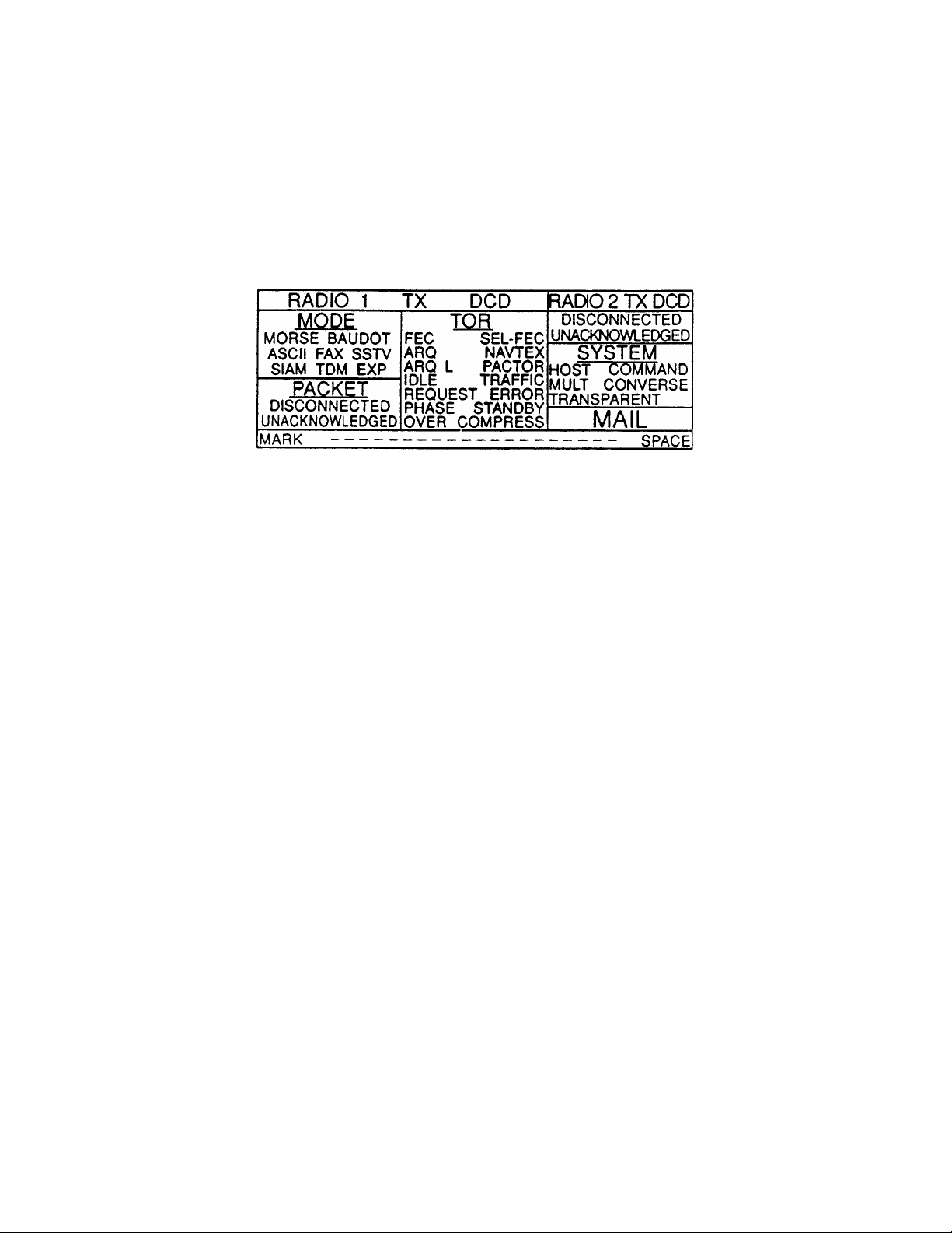
4.4 More Packet Features
Now that you have worked a few packet stations, it is time to learn a
little more about the other packet capabilities of the PK-900.
Rather than explain all the features in detail, we will leave the
specifics to the command descriptions in the Command Summary Appendix.
4.4.1 LCD Status and Mode Indicators
Your PK-900 front panel display is divided into four sections as
shown below:
PK-900's Front Panel LCD Indicators.
The left two thirds of the LCD display contain information
relating to the operation of radio port 1.
The upper right third of the LCD display contains information
about the operation of Radio port 2.
The middle of the right third of the LCD display contains
system information.
The very bottom of the LCD display is a 20 segment bargraph used
for tuning Radio port 1.
Your PK-900's front-panel LCD display shows the Status of each Radio
Port at a glance. The following describes the function of each of
the LCD annunciators.
NAME DESCRIPTION LCD FUNCTION
RADIO 1 Column Heading On when port 1 enabled
RADIO 2 Column Heading On when port 2 enabled
DCD Data Carrier Detect Lit when data signals
are received
TX Send Lit when PTT line is
active
MODE Column Heading Always on. Indicates
operating mode of port 1
MORSE Morse Code Mode Lit when in Morse mode
BAUDOT 5 Level RTTY Mode Lit when in Baudot mode
1/93 4-14
Page 57

NAME DESCRIPTION LCD FUNCTION
ASCII 7 Level RTTY Mode Lit when in ASCII mode
FAX Facsimile Mode Lit when in Facsimile
SSTV Slow Scan TV Mode Lit when in SSTV mode
SIAM Signal Identification Lit when in SIAM mode
Mode
TDM Time Division Multiplex Lit when in TDM mode
Mode
EXP Used for testing Lit when test inpt high
PACKET Packet Mode Lit when in packet
DISCONNECTED Packet status Lit when not connected
DISCONNECT Packet status Lit when disconnecting
CONNECT Packet status Lit when connecting
CONNECTED Packet status Lit when connected
UNACKNOWLEDGED Packet status Lit when you have sent a
packet that has not yet
been acknowledged
ACKNOWLEDGED Packet status Lit when all your
packets have been
acknowledged.
TOR AMTOR Mode Lit when TOR mode
FEC AMTOR or PACTOR Mode Lit when in FEC mode
ARQ AMTOR or PACTOR Mode Lit when in ARQ mode
ARQ L ARQ Listen mode Lit when in ARQ L mode
SEL-FEC AMTOR Selective Calling ModeLit when is SEL-FEC
NAVTEX NAVTEX Mode Lit when in NAVTEX
PACTOR PACTOR Mode Lit when in PACTOR
IDLE TOR Status Lit when no data is
received from an active
channel
REQUEST TOR Status Lit when data receiving
station requests repeat.
1/93 4-15
Page 58

NAME DESCRIPTION LCD FUNCTION
PHASE TOR Status Indicates synchroniza
tion of the ARQ calling
ARQ listen signal
OVER TOR Status Indicates changeover of
data transmission
direction
TRAFFIC TOR Status Indicates data reception
or transmission.
ERROR TOR Status Indicates reception of
erroneous data
STANDBY TOR Status Lit when not receiving
transmitting
COMPRESS TOR Status Lit when sending or
receiving compressed
data
SYSTEM Column Heading Always on.
HOST System status Indicates system is in
host mode. Used for
PCPackratt program
MULT System Status Lit when multiple con
nections exist
Blinks when receive
buffer is full
TRANSPARENT System Status Indicates transparent
mode.
COMMAND System Status Indicates the PK-900 is
able to accept commands
CONVERSE System Status Lit when the PK-900 is
ready to send data
MAIL Mailbox Status Lit when mailbox
contains information
MARK Bargraph Indicates mark end of
tuning indicator
SPACE Bargraph Indicates space end of
tuning indicator
4.4.2 Automatic Greetings
You can tell your PK-900 to send an automatic greeting (CTEXT) to
any station that connects to you. This can be used to tell others
1/93 4-16
Page 59

that you are out of the shack and to leave you a message or for any
other message you would like to send.
To enable the CTEXT message, set your Connect Text message using the
CTEXT command. Then set CMSG ON to enable the Connect Message
feature. Think of the CTEXT message as the message your telephone
answering machine might give to a caller.
4.4.3 Beacon Operation
Your PK-900 can send an automatic "beacon" message at a specified
time interval. A beacon can send special announcements, or let others
know you are on the air. To enable beacon operation do the following:
o Set your beacon message with the BTEXT command.
o Set the beacon interval using the BEACON EVERY or AFTER command.
o A beacon frame is sent to the path given in the UNPROTO command.
In the early days of packet, the beacon was useful to show your
presence on the packet channel. With the growth of packet, many users
feel that beacons have outlived their usefulness and interfere with
traffic. Use your beacon with consideration for others.
As a reminder, if you set the BEACON timing at a value considered too
small for busy channels (less than "90"), you'll see:
WARNING: BEACON too often
4.4.4 Digipeater Details
You may wish to connect to a packet station that is beyond your direct
radio range. If a third packet station is on the air and both you and
the station you want to talk to are in range of that third station,
the third station can relay or "digipeat" your packets. You simply
set the "digipeater" routing when you connect. Here's a sketch that
shows how digipeating can solve problems:
WX2BBB
/ \
WX1AAA _______/ \_________ WX3CCC
You are station WX1AAA - you want to have a packet QSO with WX3CCC.
There is a mountain between you and WX3CCC; you're out of simplex
range of each other. However, you know that there's a packet station
located on the ridge - WX2BBB - which is in range of you and WX3CCC.
Instruct your PK-900 to set up a connection to WX3CCC using WX2BBB
as an intermediate digipeater. When you initiate the Connect, type:
"CONNECT WX3CCC VIA WX2BBB".
If WX2BBB has turned off his station, you can still contact WX3CCC by
going around the ridge through WX2DDD and WX2EEE as shown:
1/93 4-17
Page 60

xxxx
/ \
WX1AAA _________/ \__________ WX3CCC
. .
. .
WX2DDD . . . . . . . . WX2EEE
This time, type the connect command like this:
CONNECT WX3CCC VIA WX2DDD,WX2EEE
Type the digipeaters' call signs in the exact order of the intended
path from your station to the station with which you wish to connect.
You can specify a routing list of up to eight intermediate stations.
In practice this does not work very well, and Networking Switches
such as NET/ROM have replaced digipeating for the most part. Still,
it is sometimes necessary to digipeat through one or two stations.
4.4.4.1 Are You a Digipeater?
Your packet station can be a digipeater for other stations. You don't
have to "do" anything - your PK-900 will digipeat other stations -
unless you tell it not to! with the DFROM command.
If your transmitter is keyed when you're not using it, or during lulls
in your own conversations, you're being used as a digipeater by some
other stations. This won't bother your chat with your partner.
If you wish to monitor the other stations that are using you as a
digipeater then set the command MDIGI ON.
4.4.5 Monitoring Other Stations
Use the MONITOR command to determine what kinds of packets you will
see when you are NOT connected to another station. "MONITOR" takes a
numerical value between "0" and "6." Each higher number adds more
detail to your monitoring. The meanings of the MONITOR numbers are:
0 Monitoring is disabled.
1 Only unnumbered, "unconnected" frames are displayed. This
setting will display Beacons, but not display connected stations.
2 Numbered (I) frames are also displayed. Use this setting to
monitor connected conversations in progress on the channel.
3 Connect request ("C") frames and disconnect ("D") request packets
in addition to the above are displayed.
4 This is your PK-900's default value. Unnumbered acknowledgment
(UA) of connect and disconnect frames are also displayed.
5 Receiver Ready (RR), Receiver Not Ready (RN), Reject (RJ), and
Frame Reject (FR) supervisory frames are also displayed.
6 Poll/Final bit and sequence numbers of monitored frames are shown.
1/93 4-18
Page 61

Understanding all types of packet frames is not necessary to operate
packet. Packet operators should however understand that there are
many types of control frames that do not contain printable data.
Your PK-900 can display these frames, but most users only want to
see frames with information. For this reason, the MONITOR command
default (4) does not display all the packets that the PK-900 hears.
NOTE: If you will be leaving your PK-900 on to accept connects
from others while your computer is off, set MONITOR to 0
(zero) and type a <CTRL-S> to hold the data.
If you are using an AEA program, you must set the MONITOR
command to 0, but our programs automatically perform the
<CTRL-S> function for you. If this is not done, the PK-900
memory will be filled with useless data and prevent others
from connecting with you.
4.4.5.1 Monitoring the Packet Networking Switches
There are other types of AX.25 frames used by networking switches that
the PK-900 does not normally display. These other frames can be
seen by turning the MPROTO command ON. Some of the packets monitored
with MPROTO ON will contain information that may interfere with the
screen on your terminal or computer causing it to look "funny". For
this reason the MPROTO command default is OFF.
If you are hearing packets that sound strong but are not displayed,
setting MONITOR to 6 and MPROTO ON should show them. If you are
curious about the packets that do not print, you may find the command
WHYNOT useful. When WHYNOT is turned ON, the PK-900 will give a
reason why each packet was not displayed. If you are interested in
exactly how the packets are represented, turn on the TRACE command.
See the Command Summary for more information about WHYNOT and TRACE.
4.4.5.2 Monitoring Other Stations While Connected
When you are NOT connected to another station, the MONITOR command
discussed above determines what packets are displayed. When you ARE
connected, the MCON command determines what packets are shown.
The default of MCON is 0 which tells the PK-900 NOT to monitor any
packets while you are connected. Most users like this so they are not
disturbed with monitored channel data when they are communicating with
another station. If it is desired to monitor channel activity while
you are connected, then remember to set MCON to an appropriate Monitor
number from the list in 4.4.5 or the in command summary.
4.4.5.3 Selective Monitoring
After you have monitored channel activity for a while, you may decide
there are only a few stations you wish to display. The PK-900 will
let you do this with the Monitor-TO (MTO) and Monitor-FROM (MFROM)
commands. With the MBELL command, you can even be alerted when a
certain station transmits on the frequency. These commands work in
conjunction with MONITOR and MCON commands.
1/93 4-19
Page 62

4.4.5.4 The MFILTER Command
Some terminals and computer programs are sensitive to certain
characters that may appear in monitored packets. You will know this
is happening if occasionally the cursor on your screen moves to
strange places causing the copy to be garbled.
The PK-900 default for MFILTER is $80 which prevents most control
characters from interfering with your display. If you find a terminal
or printer is bothered by certain characters, see the Command Summary
for more information on the MFILTER command.
4.4.5.5 Monitor Without Callsign Headers
Sometimes you may wish to monitor certain stations without wanting to
look at the packet callsign headers. This can be useful when
monitoring message traffic from a large Packet Bulletin Board System
(PBBS). The MBX command allows you to choose the callsign of a
station, or a pair of stations you wish to monitor without seeing the
packet headers. See the Command Summary for details.
4.4.5.6 MSTAMP, The Monitor Time-Stamp Command
Monitored packets can be time-stamped if the real-time clock has been
set with the DAYTIME command. To timestamp monitored packets, turn
the MSTAMP command ON. Turning the DAYSTAMP command ON adds the date
to the timestamp provided by the MSTAMP command.
4.4.6 Packet Connects
When you turn your PK-900 on and enter your callsign, anyone can
Connect to you. If you are at your terminal or computer when this
occurs you will see the LCD for the appropriate channel showing
the word CONNECTED.
When a packet connection occurs, the PK-900 automatically switches
to the Converse mode so what you type on the keyboard will be sent to
the connected station. The NEWMODE and NOMODE commands control when
and how the PK-900 changes to and from Command mode in response to
packet connects and disconnects. You will probably never need to
change these settings.
4.4.6.1 Time-Stamping Connects
Sometimes it is useful to know what time someone connected to you -
perhaps for logging. To time-stamp your connects and disconnects turn
the command CONSTAMP ON. As discussed in the Monitoring section
above, turning the command DAYSTAMP ON adds the date to this as well.
The DAYTIME command must first be set for this to operate.
4.4.6.2 Connect Alarm
If you busy doing other things, you may want to be alerted when
someone connects to you. Turning the command CBELL ON rings the bell
on your terminal when a station connects to, or disconnects from you.
1/93 4-20
Page 63

4.4.7 Packet Formatting and Editing
Some of your PK-900's command parameters affect how your packets are
formatted - how your typing appears to the rest of the world. Other
commands let you correct typing errors before your packet is sent,
cancel lines or cancel packets if necessary.
4.4.7.1 Carriage Returns and Linefeeds in Packets
Most people use packet radio for sending and receiving messages or
conversing with other Amateurs. The character used to send a packet
is defined with the command SENDPAC which defaults to a Carriage
Return ($0D). The SENDPAC character may be changed, but most will
find the Carriage Return or Enter key to be a natural choice.
Similarly, your PK-900 will include a Carriage Return in the packet
you send to other stations since this makes for a more natural
conversation. The ACRPACK command (default ON) controls this feature,
but most people never want to change this.
The PK-900 also has the capability of adding a linefeed character
($0A) automatically to packets that you send to others. If you
encounter a station that says your packets are overprinting, you may
want to turn the ALFPACK or the ILFPACK command ON temporarily.
4.4.7.2 Canceling Lines and Packets
Most of the time, the Backspace key (or the Delete key on some
computers) is all that is needed to edit a line before it is sent.
Occasionally it may be helpful to cancel the line, or the entire
packet you are entering with one key stroke. The CANLINE character
(default <CTRL-X>) will cancel the entire line you are typing. The
CANPAC character (default <CTRL-Y>) will delete the entire packet you
are entering. These commands can be helpful, but use them with care.
4.4.7.3 Redisplay
If you have erased and retyped many characters, you may want to see
the sentence you are currently entering "redisplayed" by the PK-900,
especially if BKONDEL is OFF. Your PK-900 will show the line you're
entering when you type the REDISPLAY character (default <CTRL-R>).
This will also allow you to display any packets you might have
received while you were typing.
4.4.7.4 The PASS Character
If you are using a terminal or terminal program, the following may be
useful. Sometimes you may want to include a special input character
such as a Carriage Return (the SENDPAC character) in a packet. For
example, to send several lines in the same packet, you must include
<CR> at the end of each line. You can include any character in a
packet (including all special characters) by prefixing that character
with the PASS character (default <CTRL-V>):
I wasn't at the meeting.<CTRL-V><CR>
What happened?
Without the PASS character, this message would go out as two packets.
1/93 4-21
Page 64

By prefixing the first <CR> with <CTRL-V>, you send it all at once,
while maintaining the <CR> as part of the text. The PASS character
can be useful in formatting text Messages such as CTEXT as well.
4.4.8 Packet Transmit Timing
Your PK-900 has a number of built-in timers used to control the
packet protocol and transmit timing. The default values have been set
at the factory to provide reasonable performance, but the values may
not be optimum for your local area. Most protocol parameters should
be adjusted only after carefully reading about them later in the
chapter. You SHOULD however adjust TXDELAY for your transmitter as
indicated below.
4.4.8.1 TXDELAY and AUDELAY
Radios vary in the time it takes to switch from receive to transmit.
If your PK-900 starts sending data before your transmitter is up to
power, the packet will not be received properly at the distant end.
TXDELAY controls the delay between your transmitter's key-up and the
moment when your PK-900 starts sending data. The default value of
30 corresponds to a time of 300 ms and works with most VHF/UHF FM
transceivers. With modern transceivers TXDELAY can often be reduced
which will improve packet performance in your area. You should
perform the following procedure to optimize TXDELAY for your radio.
o Find another station who can reliably digipeat your signals.
o Set your UNPROTO path to TEST via the callsign of the station who
can digipeat your signals. Example: UNPROTO TEST VIA WX2ABC
o Set the MONITOR command to at least 1.
o Go to CONVERSE mode and send a few packets by pressing the
<Enter> key. Note that you should see them on your own screen
when they are digipeated by the other station.
o Start reducing TXDELAY by units of 5 each time making sure the
other station is still digipeating ALL your UNPROTO packets.
Eventually you will find a value where the other station can no
longer copy your packets to digipeat them.
o When this happens, increase TXDELAY in units of one or two until
the other station again digipeats ALL of your packets. This will
be the optimum setting of TXDELAY.
After TXDELAY is adjusted as indicated above you may want to adjust
the audio delay (AUDELAY) as indicated in the Command Summary.
The next sections of this chapter will discuss some of the more
advanced packet features including Multiple Connects, Packet Timing
and Protocol, and HF Packet Operation.
4.4.8.2 AXDELAY and AXHANG
Although it is not common, packet can be used through voice repeaters.
1/93 4-22
Page 65

When sending packets through an audio repeater you may require a
longer key-up delay than is normally needed for direct communications.
The AXDELAY command adds more key-up delay in your PK-900 so that
the repeater can stabilize. The AXHANG command sets the time your
PK-900 assumes is needed for the repeater to drop.
4.5 Packet Protocol Basics
Here we will talk a little about the AX.25 packet protocol. You do
not need to know the protocol to use packet, but it helps in
understanding the protocol parameters.
There are two modes of packet transmissions, Connected mode and
Unconnected mode. Usually you will converse with another packet
station in Connected mode. Still, the Unconnected or Unprotocol mode
comes in handy for beacon transmissions and roundtable conversations.
All packets have basically the same construction. Packets contain
source and destination callsigns (and any digipeaters if used), as
well as information identifying the type of packet. This packet
identification can be seen with the MONITOR command discussed earlier.
All packets contain an error check code called the CRC. This
virtually ensures that when a packet is received, it will not con tain a single error. The command PASSALL can disable the CRC error
check, but this should only be done for experimental purposes.
4.5.1 Unconnected Packets
In order to allow amateurs to send message beacons and to call CQ, the
AX.25 protocol has the ability to send packets that are intended for
more than one specific packet station to see. Since all packets must
have a destination "callsign", the PK-900 sends Unprotocol packets
TO the callsign of CQ. This can be changed with the UNPROTO command,
but most people like this since it makes calling CQ easy.
4.5.2 Connected Packets
When you Connect to another station, the AX.25 packet protocol ensures
that the station to whom you are connected receives all the packets
that you send. Similarly, the protocol ensures you will receive all
the packets that the other station sends to you. The following
describes briefly how the protocol does this.
4.5.3 FRACK and RETRY
When the PK-900 sends a packet to a Connected station, it expects an
acknowledgment (ACK) packet from the other station to confirm that the
packet was received. The AX.25 packet protocol will automatically
retransmit (Retry) packets when an acknowledgment is not received from
the distant end of the link within a specified time.
The FRACK command (FRame ACKnowledge time) sets the time lapse allowed
before the originating station retransmits (retries) the packet.
The RETRY command sets the maximum number of retransmissions before
the sending station terminates the connection (DISCONNECTS).
1/93 4-23
Page 66

The TRIES counter keeps track of the retries that have occurred on the
current packet.
4.5.4 PACLEN and MAXFRAME
Packets will be sent either when the <Enter> key is pressed or when
the maximum packet size is exceeded. The maximum packet size is set
by the PACLEN command which defaults to 128 characters. When large
amounts of data need to be sent, this value can be increased to 256.
When conditions are poor or the channel is crowded as on HF packet,
this value should be reduced to 64 or less.
The packet protocol allows more than one frame to be sent in a single
transmission. The default is set to 4 by the MAXFRAME command. When
conditions are good up to 7 frames can be sent to speed data transfer.
When conditions are poor or the channel is crowded, MAXFRAME should be
reduced to only 1 frame.
4.5.5 Reducing Errors through Collision Avoidance
If every packet station could hear every other station, there would be
very few "collisions" due to stations transmitting at the same time.
Since packet operates over radio, there are often many stations on the
same frequency that cannot hear each other. Digipeaters and network
nodes allow these stations to communicate with each other, but this
increases the chances of collisions.
The first attempt to avoid collisions was through the use of the DWAIT
and RESPTIME timers. DWAIT forced the TNC to delay the transmission
of any packet except for digipeated frames by the time selected. This
fixed timer helped, but packet was still plagued by collisions. The
RESPTIME was added to help with large file transfers. Still, more
needed to be done to reduce collisions.
Another attempt to reduce collisions was the introduction of AX.25
version 2 protocol. On VHF packet, most everyone uses version 2 which
is controlled by the AX25L2V2 command (default ON). On VHF this
helps, but some users on HF packet are turning this command OFF.
An exponentially distributed random wait method was proposed by Phil
Karn (KA9Q) called P-persistent CSMA. When the command PPERSIST is ON
(default) the PK-900 uses the number set in PERSIST and the time
value set by the SLOTTIME command to more randomly distribute the
transmit wait time. This is more efficient than using the DWAIT time.
As a further attempt to improve packet performance, Eric Gustafson
(N7CL) proposed giving priority to acknowledgment packets (ACKs).
This protocol is controlled by the ACKPRIOR command which currently
defaults OFF. Check with experienced packet users in your area and
find out if they are using priority acknowledge or have changed any
other packet parameters.
4.5.6 CHECK and RELINK
If someone connects to you and then turns his TNC off, you would
probably not want to stay connected to the station forever. The CHECK
timer determines the amount of time the PK-900 will wait before
1/93 4-24
Page 67

testing the link if no data has been sent or received.
The RELINK command sets what happens when the CHECK timer expires. If
RELINK is OFF, the PK-900 changes to the Disconnected state. If ON,
the PK-900 attempts to reconnect to the other station.
4.6 Multiple Connection Operation
Since packet radio allows many stations to share the same channel,
many QSOs can be going on at the same time. Because packet has this
channel sharing capability, there is no reason you cannot connect to
more than one station at the same time. Being connected to multiple
stations at once is a powerful feature of your PK-900.
4.6.1 Multiple Connection Description
The PK-900 offers 10 logical packet channels on Radio Port 1 and 26
logical packet channels when using Radio Port 2. Each logical channel
can support a connection with another packet station. So with the
PK-900, you may be connected to a total of 36 other packet stations
simultaneously.
Multiple connect operation is much like a multi-line telephone with
automatic hold. When you are connected to multiple stations you
will automatically receive everything sent TO you. You must select
the proper channel (in effect push the proper line button on the
telephone) to send data to a particular station.
If you are using an AEA PAKRATT program, this is described in the
program manual. If you are using a terminal, the rest of this section
will describe how to set up the PK-900 for multiple connections.
4.6.2 The Channel Switching Character
The logical channels are selected with the CHSWITCH character. You
must choose a CHSWITCH character that you do not normally type such as
the vertical bar "|" (ASCII $7C), or the tilde "~" (ASCII $7E). Once
this has been selected and entered into the PK-900, you may initiate
multiple connections with others on your radio channel.
The ten logical channels on Radio Port 1 are numbered 0-9. The 26
logical channels on Radio Port 2 are labeled A-Z. After the CHSWITCH
character has been selected, you can now initiate connects on any of
the logical channels numbered zero through nine (0-9) on Port 1 or "A"
through "Z" on Port 2.
To change logical channels on Radio Port 1, press the CHSWITCH
character you just defined, and then a number from 0-9. Remember that
the text that you type will only be sent out to the station connected
to the logical channel your PK-900 is currently on.
This same procedure is used to select a logical channel on Radio
Port 2, only instead of pressing a channel "number" from 0-9, a
"letter" from A-Z is pressed. This is in fact the method used to
switch back and forth between Radio Ports 1 and 2. Please see the
1/93 4-25
Page 68

section on switching between Radio Ports later in this chapter for a
more complete description of this process.
4.6.3 Will You Accept Multiple Connects
Setting the CHSWITCH character only allows you to make outgoing
multiple connects. For the PK-900 to allow multiple incoming
connections, you must set the USERS parameter to more than one (1) for
each Port that you wish to allow incoming multiple connections.
The number you enter in the USERS command tells the PK-900 how many
other users you will allow to connect to you at one time. If more
than this number try to connect, they will get the "busy" response.
4.6.4 Display Multiple Connected Callsigns
Multiple Connection operation can be confusing - especially
remembering who is connected on what channel. To help this, you may
want to turn ON the CHCALL command to display the callsign of the
station who is connected to you on a given channel.
4.6.5 Doubling Received CHSWITCH Characters
If you want to be able to tell the difference between the CHSWITCH
characters you type, and characters from other stations that happen to
be the same as your CHSWITCH character, then set CHDOUBLE ON.
4.6.6 Checking Your Connect Status with the CSTATUS Command
To check what channels your PK-900 is currently set to, as well as
who is connected to you, you may find the CSTATUS command helpful.
CSTATUS is an immediate command that shows you the status of all
packet channels as well as the channel you are currently on.
4.6.7 The MULT LCD
You will know you are connected to more than one packet station on
each Radio Port when the MULT LCD the PK-900 lights.
NOTE: The MULT LCD will blink if the PK-900's receive buffer is
filled. This can happen if your computer is not connected to
the PK-900 and the MONITOR command was left ON, or if for
some reason, your communications program no longer can accept
any further inbound data.
4.7 HF Packet Operation
HF Packet is much trickier than operating on VHF. In this section we
will assume you have as completed section 4.2 of this chapter and at
least read section 4.3 and the MONITORING sections of 4.4. If at all
possible, get some experience with VHF packet before trying packet on
HF. Although this is not absolutely required, the experience will
help you make HF packet contacts.
1/93 4-26
Page 69

4.7.1 Where to Operate HF Packet
Before you can operate HF Packet, you must first find the activity.
Most HF packet operation is on the 20-meter amateur band starting at
14.103 MHz and every 2 kHz above that up to 14.111 MHz. Note that
14.103 MHz is the HF Packet calling frequency and a good place to
start. The higher frequencies such as 14.109 and 14.111 are used
mostly by HF PBBS systems and are not good places to look for a QSO.
4.7.2 PK-900 HF Packet Settings
Radio Port 1 on the PK-900 is intended for multi-mode operation so
either a VHF or HF transceiver may be connected. The packet
parameter defaults have been set for VHF Packet operation on both
radio ports and should be changed for HF packet operation as shown
in the table below.
The table below shows the parameters that should be set differently
for HF and VHF packet operation. If you will be operating HF Packet,
you should make note of these parameters and change them accordingly.
Recommended Port 1 & 2 Defaults
300 baud HF Packet 1200 baud VHF Packet
SLOTTIME 12 SLOTTIME 30
PACLEN 64 or less PACLEN 128
MAXFRAME 1 MAXFRAME 4
FRACK 8 FRACK 5
VHF OFF VHF ON
HBAUD 300 HBAUD 1200
MODEM 10 MODEM 11/4
Note that the HF (VHF OFF) modem number is tied to the QHPACKET
command and the VHF (VHF ON) modem number is tied to QVPACKET.
The Radio Port baud rate is not changed when you change modems. You
select the appropriate baud rate with the HBaud command.
You should set MONITOR to 6 on the port used for HF Packet when tuning
in your first HF Packet stations.
4.7.3 HF Receiver Settings
Set your HF receiver (or transceiver) to Lower Sideband (LSB) unless
you connected your PK-900 through the direct FSK keying lines, in
which case you should select the FSK or RTTY operating mode. Adjust
the volume to a comfortable listening level.
4.7.4 Tuning in HF Packet Stations
Perhaps the most difficult thing about HF Packet operation is making
sure the station is tuned properly and stays tuned. Since HF packet
uses 200 Hz Frequency Shift Keying to send data (2110/2310 Hz),
tuning accuracy is very important. Being off frequency by only 20
Hz can make a noticeable difference in the PK-900's ability to copy
packet stations. Your have a choice of three types of tuning indi cator types. Use the BARgraph command to change the indicator type.
1/93 4-27
Page 70

Follow the tuning procedure below carefully for the best results in
tuning in HF packet stations.
o Make certain your HF receiver is either in LSB or FSK depending
on your PK-900 set-up.
o Turn any IF-Shift and Passband-Tuning controls to the Center or
OFF position.
o Tune your receiver to 14.103 MHz (or another frequency where you
know there is HF packet activity) and listen to the packets.
o Slowly vary the tuning knob on your receiver and look for a
display on the PK-900 tuning indicator like the one below.
——————————————————————————————————————————————————————————————
MARK | | SPACE
——————————————————————————————————————————————————————————————
Tuning correct for discriminator indicator (BAR 0)
——————————————————————————————————————————————————————————————
| |
——————————————————————————————————————————————————————————————
Tuning correct for magic eye indicator (BAR 3)
——————————————————————————————————————————————————————————————
| |
——————————————————————————————————————————————————————————————
Tuning correct for center tune indicator (BAR 2)
If the tuning indicator looks like the one below, the audio
frequency from your speaker is too low for the PK-900 to copy
packets. Slowly tune the VFO and make the frequency higher.
——————————————————————————————————————————————————————————————
MARK | | SPACE
——————————————————————————————————————————————————————————————
Tuning too low for discriminator indicator (BAR 0)
——————————————————————————————————————————————————————————————
| |
——————————————————————————————————————————————————————————————
Tuning too low for magic eye indicator (BAR 3)
——————————————————————————————————————————————————————————————
| |
——————————————————————————————————————————————————————————————
Tuning too low for center tune indicator (BAR 2)
3/93 4-28
Page 71

If the tuning indicator looks like the one below, the audio
frequency from your speaker is too high for the PK-900 to copy
packets. Slowly tune the VFO and make the frequency lower.
——————————————————————————————————————————————————————————————
MARK | | SPACE
——————————————————————————————————————————————————————————————
Tuning too high for discriminator indicator (BAR 0)
——————————————————————————————————————————————————————————————
| |
——————————————————————————————————————————————————————————————
Tuning too high for magic eye indicator (BAR 3)
——————————————————————————————————————————————————————————————
| |
——————————————————————————————————————————————————————————————
Tuning too high for center tune indicator (BAR 2)
o Adjust the volume on the receiver so that the DCD LCD lights
when a properly tuned packet is being received.
You must also make certain that the DCD LCD goes out when no
packet signals are present on the frequency.
After you have a packet station tuned in, you should start seeing
HF packet stations on your display.
4.7.5 Transmitter Adjustments
Make sure your PK-900 is adjusted for your SSB transmitter as
described in section 3.5 and 3.5.2 of this manual before transmitting.
These are very critical adjustments. If the AFSK level and
transmitter microphone gain are not adjusted properly, other stations
will not be able to copy your packets. Check your plate or collector
current or the power output of your rig before going on the air.
4.7.6 Going On The Air
Make sure your transmitter and antenna are tuned and adjusted for the
band and operating frequency you are using.
On HF there are two ways you can go about talking to another station.
o First, you can look at the packets you have just MONITORED
(or in your MHEARD list) and choose one of them to connect to.
o You can also "Call CQ" by entering the CONVERSE mode and pressing
the <Enter> key a few times.
Either way you decide to go on the air, remember that things happen
much more slowly on HF packet than they do on VHF packet. HF packet
requires patience and careful tuning in order to be used successfully.
3/93 4-29
Page 72

If you are having problems connecting to other HF packet stations, try
working with an experienced HF packet operator in your area and listen
to each other's signals. See if you can copy each other's packet
signals. If he cannot copy your signals, have him listen to your
signal in the CALIBRATE mode to make sure you are transmitting a pure
tone. As mentioned earlier, any distortion caused by overmodulation
or RF feedback will make your signal difficult or impossible to copy.
4.8 Controlling the Radio Ports
If you are using an AEA PAKRATT program designed for the PK-900,
switching between Radio Ports is described in the program manual.
If you are using a computer terminal, terminal program or the
"Dumb Terminal Mode" of an older PAKRATT program, this section will
describe how to control and switch between the radio ports. The
RADIO command allows either (or both) Radio Port(s) to be disabled.
Before the second radio port can be used for packet operation, the
proper modem must be selected using the 2MODem command.
Radio Port 2 Modems
1: Internal 200: 1070/1270 2: Internal 200: 2025/2225
3: Internal 1000: 1200/2200 4: Internal 1000: 1200/2200 eq.
5: Internal 200: 1180/980 6: Internal 200: 1850/1650
7: Internal 800: 2100/1300 8: Internal 800: 2100/1300 eq.
9: Internal option 10: Modem disconnect header
4.8.1 Selecting Modems
The various modems available in the PK-900 can be seen with the
DIRECT(ory) command. To display all the available modems simply
enter the Command Mode of the PK-900 and then type DIR as shown.
DIR <Enter>
The PK-900 will respond with the following:
- Port 1 - - Port 2 1: FSK 45 bps 170: 2125/2295 1: Internal 200: 1070/1270
2: FSK 100 bps 170: 2125/2295 2: Internal 200: 2025/2225
3: FSK 45 bps 200: 2110/2310 3: Internal 1000: 1200/2200
4: FSK 100 bps 200: 2110/2310 4: Internal 1000: 1200/2200 eq.
5: FSK 100 bps 425: 2125/2550 5: Internal 200: 1180/980
6: FSK 100 bps 850: 2125/2975 6: Internal 200: 1850/1650
7: FSK 100 bps 850: 1275/2125 7: Internal 800: 2100/1300
8: Analog 900/2500 8: Internal 800: 2100/1300 eq.
9: FSK 2400 bps 800: 1300/2100 9: Internal option
10: FSK 300 bps 200: 2110/2310 10: Modem disconnect header
11: FSK 1200 bps 1000: 1200/2200
12: Morse 750
3/93 4-30
Page 73

Any modem from this list may be selected with the command MODEM. For
example, let's say that you want to operate 300 bps HF packet on radio
port 1 and 1200 bps VHF packet on radio port 2.
This operation is achieved with radio port 1 modem 10 and radio
port 2 modem 4. To load these modems, first enter the Command
Mode of the PK-900 and then type MODEM 10/4 as shown below:
MODEM 10/4 <Enter>
The PK-900 will respond with the following:
MODem was x/x (whatever modems were in use)
MODem now 10/4
cmd:*** HBaud now 300/1200
Either modem may be selected individually. To change only radio
port one's modem, for example, type MODEM 10 <Enter>. To change
only radio port two's modem, you would type MODEM /4 <Enter>.
4.8.2 Displaying Received Data
When radio port 2 is active in the PK-900, received data is displayed
from both Radio Ports at the same time. This allows you to operate
on HF and not miss any local Packet connects or information from VHF
DX spotting nets.
The PK-900 displays monitored packets by prefacing each packet with
a port designator "p1" for radio port 1 and "p2" for radio port 2.
For instance, let's say that modems 10/4 are selected and you
are monitoring HF packet activity on Radio Port 1, and VHF packet
activity on Radio Port 2. You might see something like the following:
p1 WX1AAA*>CQ [UI]: { WX1AAA calling CQ on
Radio Port 1 (HF) }
p1 WX1AAA*>CQ [UI]:
p2 WY7DDD*>WY7EEE [I,P;1,1]: { An Information Frame from
Hello Bob, how are you? WY7DDD to WY7EEE monitored
on Radio Port 2 (VHF) }
p2 WY7EEE*>WY7DDD (RR,F;1) { Acknowledgment of the above
I-Frame on Radio Port 2 }
p1 WX2BBB*>WX1AAA [C,P] { WX2BBB attempting to connect
to WX1AAA on Radio Port 1 }
p1 WX1AAA*>WX2BBB (UA,F) { WX1AAA acknowledging the
connect request }
p1 WX2BBB*>WX1AAA [I,P;0,0]: { An Information Frame from
Hello Bob, how are you? WX2BBB to WX1AAA monitored
on Radio Port 1 (HF) }
The first packet shown above is an Unprotocol "CQ" packet from WX1AAA
that was received on Radio Port 1. We know this was received on Port
1 because of the "p1" shown in front of the packet. (Remember from
1/93 4-31
Page 74

the section on Multi-connect packet operation that Packets received on
Radio port 1 will be on one of the ten logical channels numbered 0-9.)
The second packet is another "CQ" from WX1AAA. Again, there is a "p1"
in front of it so we know it was also received on Radio Port 1.
The third packet is an Information-Frame, or simply an "I-Frame" that
was monitored on Radio Port 2. We know this was received on Radio
Port 2 because of the "p2" shown before the packet.
Remember that Packets received on Radio port 2 will be on one of the
26 logical channels designated A-Z.
The fourth packet is an acknowledgment to the previous I-Frame
received on Radio Port 2. Again, the "p2" in front of the packet
tells us it was received on Radio Port 2.
The fifth packet is a Connect Request from WX2BBB to WX1AAA that was
monitored on Radio Port 1. The "p1" in front tells us so. The sixth
packet is an acknowledgment by WX1AAA to the connect request.
The seventh and last packet shown above, is the first I-Frame that
WX2BBB is sending to WX1AAA after they have connected.
4.8.3 Controlling Your Transmitted Text
If you are using an AEA PAKRATT program designed for the PK-900,
switching between Radio Ports is described in the program manual.
If you are using a computer terminal, terminal program or the
"Dumb Terminal Mode" of an older PAKRATT program, this section will
describe how to control and switch between the radio ports.
4.8.3.1 Defining the Channel Switching Character CHSWITCH
Before you can switch between logical channels or Radio Ports you must
define a Channel Switching character that you will use to signal the
PK-900 that you want to redirect your transmitted text. This
special character is defined with the CHSWITCH command and should be
one that you do not normally type in conversational text such as the
vertical bar "|" ($7C), or the tilde "~" ($7E). To enter the vertical
bar "|" as the CHSWITCH character, first enter the Command Mode of the
PK-900 and then type CHSWITCH $7C as shown below:
CHSWITCH $7C <Enter>
The PK-900 will respond with the following:
CHSWitch was $00
CHSWitch now $7C (|)
Once a CHSWITCH character has been entered, you may switch Radio
Ports or Packet logical channels of the PK-900 at will.
1/93 4-32
Page 75

4.8.3.2 Switching Between Radio Ports
The ten logical channels on Radio Port 1 are labeled 0-9. The 26
logical channels on Radio Port 2 are labeled A-Z. To select Radio
Port 1, press the CHSWITCH character you just defined, followed by a
number from 0-9. To select Radio Port 2, press the CHSWITCH
character, followed by a letter from A-Z.
After you change Radio Ports or logical channels, the text you type in
the CONVERSE mode will be sent to the port and channel selected. If
you are connected to another packet station, the text you type will be
sent to him or her. If the channel is not connected, the text will be
sent in the Unprotocol or unconnected mode.
For example, let's say that you are operating HF Packet on Radio Port
1 and are also available for connects on the local VHF Packet channel
on port 2. You connect to an HF packet station and are in the middle
of a QSO when a station on VHF connects to you. The following shows
how your screen would look and suggests how you might handle such an
occurrence. The underlined text is the text that you have typed.
p1 WX1AAA*>CQ [UI]: { WX1AAA calling CQ on
Radio Port 1 (HF) }
p1 WX1AAA*>CQ [UI]:
cmd:C WX1AAA { You attempt to connect to
station WX1AAA on HF }
*** CONNECTED to WX1AAA { You're connected to WX1AAA }
Hello, name here is Bob. { You send him your name }
Hi Bob, name here is Jim and the { The other station responds
QTH is Boston Mass. with his name and location }
A:*** CONNECTED to WX7EEE { WX7EEE connects to you on
VHF (Radio Port 2) }
Nice to meet you Jim, QTH here is { You send another packet
Seattle, WA. You have a nice signal. to Jim on HF }
Hey Bob, I'm going to the hamfest { Your friend on VHF packet
this weekend if you want a ride. wants to go to the hamfest }
|AHello Mike, I am on HF right { You switch ports by typing
now talking to a station in Boston. |A and respond on VHF }
0:Thanks Bob, your signal is S-7 { Jim on HF gives you a signal
here. I am running 100 Watts into a report. The "0:" shows you
tri-bander at 50 ft. this was from Port 1 (HF) }
|0Thanks for the report Jim, you're { You switch back to HF with
S-8 and the antenna here is a quad. the |0 and respond to Jim }
1/93 4-33
Page 76

|AYes, I was planning to go Saturday. { You switch to Port 2 with
What time do you want to leave? |A to say you want to go }
A:I'll pick you up at 8:00 Bob. { Your friend on VHF responds
I'm looking forward to it. to you }
0:Well, it's getting late here and { Jim on HF tells you he has
time to pull the plug Bob. shut down for the night }
Sounds good, I'll see you on { You last sent data on Port 2
Saturday morning. and do not need to send |A }
|0Take care Jim, and 73. { You say 73 to Jim on HF }
A:73 Bob. { Your friend on VHF says 73 }
|A<Ctrl-C>A:cmd:D <Enter> { You switch to Port 2 and
Disconnect from WX7EEE }
*** DISCONNECTED: WX7EEE { You're now disconnected from
WX7EEE on VHF. The A:
doesn't show because you last
received data on port 2. }
0:*** DISCONNECTED: WX1AAA { WX1AAA disconnects from you
on HF (Port 0 }
As you may have noticed, the above technique of communicating on more
than one Port at the same time is almost identical to that used for
single-port multiconnect packet operation. Let's discuss the sample
QSOs above to see how the Port switching occurs.
The first packet frame, we see is a CQ from WX1AAA. This frame is
preceded by a "p1" which shows it was received on Radio Port 1.
You have seen WX1AAA calling CQ and decide to connect to him on HF.
You simply go to the Command mode (by typing <CTRL-C>) and issue the
CONNECT command C WX1AAA as shown on the third line. The fourth line
shows that you are now Connected to WX1AAA. Note that you did not
have to type "|0" before sending the connect request since the
PK-900 defaults to Port 1 until it has been changed to Port 2. If you
want to be sure of which channel you want to be on, you could type |0.
Now that you are connected to WX1AAA you greet him and send your name.
WX1AAA then gives you his name (Jim) and location which is the way
most QSOs begin. Remember in the above example, the underlined text
is the text you would have typed.
You have just begun your QSO with WX1AAA when all of a sudden your
friend WX7EEE connects to you. WX7EEE has connected on Radio Port 2
(VHF) which is shown by the "A:" before the connect message. Remember
that the 26 channel designators for Radio Port 2 are A-Z.
Before you respond to WX7EEE on VHF, you send a packet to Jim on HF
giving him your location. After sending this packet, you see WX7EEE
on VHF has offered you a ride to the hamfest. We know this packet is
from Radio Port 2 since the previous packet displayed by the PK-900
1/93 4-34
Page 77

was the "A:*** CONNECTED" message from Port 2.
Now you want to let WX7EEE on VHF know that you are there, but that
you are involved in another QSO on HF. This way he will understand
that it may take you a little longer to respond to his packets.
Before you can send data to Radio Port 2, you must switch to this Port
with "|A" or the text you type will be sent to Radio Port 1.
You receive another packet from Jim on HF giving you a signal report
and describing his antenna. Again, the "0:" in front of the text
shows this was received on Port 1.
Now you want to give Jim a signal report so you must switch to Port 1
with |0 before your text or it will be sent to WX7EEE on Port 2.
After sending Jim a signal report, you tell your friend on VHF that
you want to go to the hamfest with him. You must switch back to
Port 2 by typing |A before sending to WX7EEE.
In the next received packet, we see that WX7EEE on VHF agrees to pick
you up at 8:00 to go to the hamfest. The "A:" in front of the packet
shows that this packet was received on Port 2.
Immediately following, you see a packet from Jim on HF saying it's
time to shut down. The "0:" identifies this as a Port 1 packet.
The last packet you sent was to WX7EEE on VHF so you decide to reply
to him first. This way you do not have to change Ports. After your
reply to WX7EEE, you change to Port 1 with |0 and send your good-byes
to Jim on HF.
Your friend WX7EEE on VHF says 73 and signs off with you. After two
stations agree to sign off, one of them must initiate a Disconnect.
You decide to disconnect from WX7EEE by first switching to Port 2 with
|A and then entering Command mode with a <Ctrl-C>. Once you see the
Command prompt (cmd:), enter the Disconnect "D" command.
Shortly after you do this you see the display
"*** DISCONNECTED: WX7EEE" from the PK-900.
Jim on HF has decided to initiate the disconnect with you so the final
packet you see is the "0:*** DISCONNECTED: WX1AAA" frame from Port 1.
4.8.3.3 More Thoughts on Port Switching
One problem of having more than one Radio Port is remembering which
port you are currently using. In the dual port sample QSOs above,
this was not a problem, but after it has been hours or days since you
have used your PK-900, you may forget which port you last used.
With AEA Pakratt Software programs, the on-screen status will always
show which port you are using so this is not a problem. With other
programs, you will have to query the PK-900 with the CSTATUS SHORT
command. The CSTATUS command displays the status of the logical
channels of Port 1 and Port 2 of the PK-900. The CSTATUS SHORT
command displays the status of the active channel and any other
connected packet channels. After completing the sample QSOs above,
the PK-900 would display the following.
1/93 4-35
Page 78

cmd:CSTATUS S
Ch. A - IO DISCONNECTED
This reminds you that Channel A is your current I/O channel. Any text
that you type in the Converse mode will be sent to channel A on Radio
Port 2. If you had been connected to any other packet stations, the
callsign and channel would have also shown in the display.
Sometimes you might not want to be bothered with anything from the
Radio Port you are not using. For these times either Radio Port may
be turned OFF with the RADIO command. For example, let's say that in
the above example QSO you wanted to work HF packet and did not want to
be interrupted with any VHF connects. Typing the following command
would cause Radio Port 2 to be disabled.
cmd:RADIO /0
RAdio was 1/2
RAdio now 1/0
When a PK-900 Radio Port is disabled, the front panel LCD Status
indicator for that port will be extinguished as a reminder.
4.9 Advanced Packet Operation
Your PK-900 has many commands and features that are not used for
day-to-day connects conversations. Still, as you become more familiar
with packet, some of these features may become important to you.
4.9.1 Transparent Mode
The TRANSPARENT mode allows any 8-bit binary character to be sent by
your packet station. You usually must use the TRANSPARENT mode to
transfer binary and program files to and from other stations.
You can enter the TRANSPARENT mode either by typing TRANS at the cmd:
prompt after you connect, or by setting CONMODE to TRANS. Either way,
once in the transparent mode, any character you type will be sent
automatically after the PACTIME setting. This way the PK-900 can
send any character. We recommend using HARDWARE flow control in
transparent mode but SOFTWARE flow control is available with the
TRFLOW and TXFLOW commands. To get back to Command mode after you are
finished with transparent mode, you must type the COMMAND character
(default <CTRL-C>) 3 times within the "Guard time" set by the
CMDTIME command (default 1 second). (Hold down the CTRL key and press
C three times rapidly.)
4.9.2 Gateway Operation
The PK-900 can allow packet stations on one radio port to communicate
with stations on the other port. When the PK-900 bridges two packet
frequencies in this manner, it is said to be a "Gateway." Gateway
operation is a dual port feature and requires that the correct
port 2 packet modem be loaded. Once this has been done the gateway
function is enabled by entering a callsign in MYGATE. The callsign
must not be the same call sign and SSID as MYCALL or MYMAIL.
1/93 4-36
Page 79

When another station digipeats via the callsign in MYGATE, your
PK-900 will Gateway between Radio Port 1 and Radio Port 2. If you
provide this feature to users in your area, you may want to BEACON a
message on both ports informing users that your gateway is available.
At this time however, unattended operation below 30 MHz is not legal
for US amateurs unless they hold a Special Temporary Authorization
(STA) from the FCC. This restriction may someday change, but until
then US amateurs must always have control of their HF transmitters
when an automatic device such as the PK-900 Gateway is in use.
4.9.3 Sending 8-bit Data in Converse Mode
Sometimes you may need to send a file that contains some 8-bit data,
but not need all the features of the TRANSPARENT mode. In this case,
you may find turning the command 8BITCONV ON is all that is needed.
4.9.4 The Packet QRA Feature
The PK-900 recognizes UI frames with a destination field of "QRA"
and will respond by sending an ID packet. This is helpful for others
new to your area that are looking for other packet stations to talk
to. To disable this feature and remain anonymous, simply set User
BIT 22 OFF (UBIT 22 OFF). The default is ON.
If you wish to see who is available in your local area, simply set
your UNPROTO path to QRA and send a packet. Within 1 to 16 seconds
other stations should respond to your QRA request by sending an ID
packet of their own. This feature is compatible with TAPR's QRA
feature introduced in the 1.1.8 firmware release.
4.9.5 The CFROM Command
If you ever want to exclude certain stations from connecting or only
allow friends to connect, you may do so with the CFROM Command. See
The Command Summary for details of its operation.
4.9.6 Operating in Full-Duplex
Most packet operation is carried on over Half-Duplex transceivers that
can transmit and receive but not do both at the same time. When a
separate transmitter and receiver is used such as in satellite
operation, you may want to use the FULLDUP Command in the PK-900.
4.9.7 Identifying as a Digipeater
If your PK-900 is being used as the primary digipeater in a local
area, you may want to enable the HID command. HID will automatically
identify your station for others to see.
4.9.8 Digipeater Alias Callsign
If your packet station is being used as the primary digipeater in your
local area, you may want to choose a simpler identifier for others to
use with the MYALIAS Command.
1/93 4-37
Page 80

4.9.9 Morse ID in Packet
In most countries, packet is an accepted mode of identification so
this command should be left OFF. In some countries, however, a Morse
ID is required when packet is used and so the MID command should be
enabled.
4.9.10 Sharing Packet Channels with Voice Operation
Although it is seldom needed, the PK-900 does have an input for
SQUELCH information from a transceiver on the RADIO connectors. This
input should be used and the SQUELCH command set if the packet channel
is to be shared with voice operation.
4.9.11 Disabling Transmit Operation
Occasionally for test purposes it may be desired to disable the PTT
circuit in the PK-900. This is done with the XMITOK Command.
4.10 Seldom Used Commands
The following commands operate in Packet, but are seldom needed.
They are listed for reference and described in the Command Summary.
AFilter BBSmsgs CONPerm CPactime DCdconn Flow HEAderln
MDMon MRpt MXmit
4.11 Packet Lite HF Packet Protocol Extension
Amateur radio needs a better communications mode for HF operation.
Baudot and ASCII have no provision for error detection. AMTOR FEC and
ARQ are more resistant to errors, but do not carry the full ASCII
character set. 300 baud AX.25 packet is undesirable because the long
transmissions are prone to bit errors, any one of which invalidate the
whole frame. PACTOR is a recent protocol improvement.
Packet Lite is, as its name suggests, an abbreviated form of packet.
It is designed as a transparent extension to the AX.25 protocol that
reduces the "overhead" of all HF packet frames without digipeaters.
Packet Lite does not solve HF packet's problems, but it should provide
some throughput improvement on HF where it is desperately needed.
AEA's engineering department is interested in hearing from Packet Lite
users with any comments or suggestions on improving the protocol.
A Brief Description of the Packet Lite Protocol
The main feature of Packet Lite that reduces overhead is that it uses
an address field of only 4 bytes. A standard AX.25 header without
digipeaters uses 14 bytes of addressing. Shortening the packet frame
header lessens the possibility of any given frame taking a hit.
Packet Lite reduces the length of an I-frame slightly, but its real
strength is the shortening of the acknowledgment frames, resulting in
1/93 4-38
Page 81

fewer garbled acks and therefore fewer unnecessary retries. An ack
(RR, RNR or REJ frame) in standard AX.25 consists of 19 consecutive
bytes that must be copied with no hits; Packet Lite reduces the length
to 9 bytes, or 47% of the standard ack length.
A couple of restrictions are necessary to accomplish this.
First, Packet Lite works only between two stations connected directly,
with no digipeating allowed. If digipeaters are introduced to the
address field, the advantage of the reduced overhead disappears.
Second, all Packet Lite connections emulate AX.25 version 2.0 (RR
polling instead of retrying I-frames). This is necessary for the 10 minute identification described below. Also, the main reason version
1 continues to be used on HF is that on a retry a [RR,P] polling frame
is so long that one might as well just send the I-frame again. Packet
Lite's polling and ack frames are so short that the AX.25 version 2.0
polling method is now worth doing.
4.11.1 Enabling Packet Lite
To begin using Packet Lite, first make sure you have made all the
proper HF Packet settings discussed earlier in this chapter. Be
careful to ensure VHF is OFF and a 300 bps Modem has been selected.
Once these settings have been made, to enable the Packet Lite protocol
extensions, turn the command LITE ON for the appropriate Port.
For example to enable Packet Lite on Port 1, type "LITE ON" at the
command prompt. You must not be connected to any other stations on
that Port or you will not be allowed to change the LITE command.
Initiating a Packet Lite Connection
Once all the above settings have been made, simply issue the standard
CONNECT request as described earlier in the chapter.
If the station you are connecting to also has Packet Lite enabled, a
Packet Lite connection will result and you and the distant station
should enjoy a more reliable QSO than others on the same frequency.
4.11.2 Compatibility With Standard AX.25 Stations
If the station you connect to does not have the Packet LITE protocol
extensions, there are three known possibilities that will occur.
1. WA1ABC>WB2XYZ [C,P] 01 3E 38 58 32 {Packet Lite attempt}
WB2XYZ>WA1ABC (UA,F) {Standard ack}
In this case, the non-Lite station sees the [C,P] control byte but
ignores the non-standard bytes following it. It replies with a
standard UA frame, and the connection proceeds as standard AX.25.
2. WA1ABC>WB2XYZ [C,P] 01 3E 38 58 32 {Packet Lite attempt}
WB2XYZ>WA1ABC (FR): 3F 00 03 {Frame Reject}
WA1ABC>WB2XYZ [C,P] {Standard attempt}
WB2XYZ>WA1ABC (UA,F) {Standard ack}
1/93 4-39
Page 82

In this case, the non-Lite station notices the non-standard bytes
following the control byte and issues a FRMR (Frame Reject) to signify
that a protocol violation has taken place. The PK-900 receives the
FRMR and automatically reverts to standard AX.25, sending the connect
retries without the Lite PID and address bytes.
3. WA1ABC>WB2XYZ [C,P] 01 3E 38 58 32 {Packet Lite attempt}
... {No response}
In this case, the non-Lite station notices the non-standard bytes
following the control byte but sends no response at all. If this
occurs, you must turn the command LITE OFF and try to connect again to
the distant station. No adverse effects are caused by this, but
transparency with standard AX.25 is lost when the receiving station
does not acknowledge a Packet Lite connect request in some manner.
We know that TCP/IP, NET-ROM and DRSI stations ignore Packet Lite
Connect requests. These stations are normally found on VHF, but to be
safe, the LITE command should be turned OFF when not in use.
4.11.3 Packet Lite Protocol Enhancement Summary
The following describes the Packet Lite protocol extension in depth
for those interested in the technical details. It is not necessary to
read or understand the following section to use the protocol.
Here is a summary of a Packet Lite exchange, where WA1ABC calls WB2XYZ:
Connect:
W B 2 X Y Z -0 W A 1 A B C -0 SABM 01 3E 38 58 32
destination | source | CTRL PID | short address
The destination and the source are both 7 bytes long. Everything up
to the CTRL byte (SABM) is standard AX.25 version 2.0. The "Protocol
ID" of 01 hex is Packet Lite's reserved value, which provides a way of
interpreting the following bytes. This leaves room for other
extensions to AX.25 in the future. The short address bytes are the
right-justified bytes of the address field that WA1ABC proposes to use
in subsequent Packet Lite frames with WB2XYZ. In this case, the AEA
implementation of the short address is illustrated. 3E38 is a
compressed version of the destination WB2XYZ and 5832 is a compression
of WA1ABC. However, any combination of 26 bits may be used
(see "Technical Details" below).
Connect acknowledgment:
W A 1 A B C -0 W B 2 X Y Z -0 UA 01 58 32 3E 38
destination | source | CTRL PID | short address
WB2XYZ replies to WA1ABC. Again everything up to the CTRL byte (UA)
is standard AX.25. The "PID" of 01 and the short address confirm that
WB2XYZ has accepted the Packet Lite connection. The short address is
again the right-justified representation of the address field that
WB2XYZ will be using in subsequent Packet Lite transmissions. In this
case WB2XYZ has accepted the short address field suggested by WA1ABC,
and has shown his acceptance by echoing the address back in reverse
order (5832 = WA1ABC and 3E38 = WB2XYZ). AEA products always accept
the short address from the SABM frame; however, the Packet Lite
protocol allows the sender of the UA frame to propose a different
1/93 4-40
Page 83

combination of 26 bits, to avoid conflicting with another Lite QSO.
In either case, the sender of the original SABM must accept the 26
bits in the UA frame, reversing the address order for its own
transmissions.
Transmission of data:
7C F0 B0 65 10 F0 Test <CR>
3E38 shifted 5832 shifted [I,P;0,0]
short dest. short source CTRL PID text
WA1ABC sends data to WB2XYZ in Packet Lite format. The address field
consists of the short address from WB2XYZ's UA frame, reversed and
left-shifted. The added bits come from AX.25 version 2.0's command
and response bits, and the end-of-address bit.
Acknowledgment of data:
B0 64 7C F1 31
5832 shifted 3E38 shifted (RR,F;1)
short dest. short source CTRL
WB2XYZ acknowledges the data from WA1ABC. The address field is
reversed. This is the shortest length frame possible in Packet Lite.
4 address bytes + 1 CTRL byte + 2 flags + 2 CRC bytes = 9 bytes.
Every 10 minutes the stations must identify using both long and short
addresses:
W B 2 X Y Z -0 W A 1 A B C -0 [RR,P;0] 01 3E 38 58 32
destination | source | CTRL PID | short address
W A 1 A B C -0 W B 2 X Y Z -0 (RR,F;1) 01 58 32 3E 38
destination | source | CTRL PID | short address
Either station may initiate the ID exchange.
Disconnect:
W B 2 X Y Z -0 W A 1 A B C -0 DISC 01 3E 38 58 32
destination | source | CTRL PID | short address
Disconnect acknowledgment:
W A 1 A B C -0 W B 2 X Y Z -0 UA 01 58 32 3E 38
destination | source | CTRL PID | short address
At the end of the connection, the two stations must once again
identify using both long and short addresses.
AEA firmware supporting Packet Lite also contains code that permits
monitoring of Packet Lite and extended AX.25 frames.
Packet Lite Shortened Address Technical Details
The Packet Lite address field consists of 26 bits distributed over 4
bytes (or octets, as the AX.25 specification calls them). These bits
are considered to be two groups of 13 bits each, roughly equivalent to
a destination and a source ID. If we label the bits A-Z and show
their use in the address field of a Lite frame, the bits are
distributed as follows:
1/93 4-41
Page 84

A B C D E F G 0 x H I J K L M 0 N O P Q R S T 0 y U V W X Y Z 1
The least significant bit of each byte is used to show whether or not
the byte is the final byte in the address field, as in standard AX.25.
The bits "x" and "y" (lower case) have the function of command and
response, similar to the function of the standard AX.25 version 2.0
SSID byte C bits (see AX.25 Protocol version 2.0, section 2.4.1.2).
In the AEA implementation of Lite addressing, the standard callsigns
are compressed to yield short addresses. The destination callsign is
compressed into bits A-M, and the source into N-Z. These bits are
used as the address field suggestion following the control byte in the
Connect (SABM) frame. When the bits are used following the control
byte as an ID suggestion or a real extended ID, the format is:
0 A B C D E F G 0 0 H I J K L M 0 N O P Q R S T 0 0 U V W X Y Z
If we label the 7 standard right-justified callsign bytes 1-6 and
SSID, here is how we derive the first group of address bits A-M:
ABCDE = (byte 1 XOR byte 4) AND $1F
FGHI = (byte 2 XOR byte 5) AND $0F
JKLM = (byte 3 XOR byte 6 XOR SSID) AND $0F
AEA firmware derives the second group of bits N-Z the same way. Other
implementations are free to select any combination of 26 bits when
setting up the short address in either the initial SABM frame or its
UA response.
4.12 Packet Meteor Scatter Extension
A new packet protocol extension has been added for meteor scatter
work that allows a Master/Slave packet connection to be established.
This is done to reduce the possibility of simultaneous transmissions
by both sides of a packet connection over a long meteor scatter path.
This experimental protocol is activated by turning User BIT 18 ON
(UBIT 18 ON). When UBIT 18 is ON (default OFF) the packet station
who initiates a packet connect will become the Master station and the
station who acknowledges the connect becomes the Slave.
After a Meteor Scatter connection has been established, the Master
station will continually send either information frames (I-frames)
or polling frames and await an acknowledgement from the slave. The
Master station therefore sends packets constantly, even if all its
I-frames have been acknowledged. The slave station sends nothing,
not even I-frames, until it receives a polling frame from the master.
The Slave station may only send an I-frame to the Master after a
poll frame has been received.
The packet timing of the Master station is critical for proper Meteor
Scatter operation. In a normal AX.25 packet connect, the FRACK timer
counts down until it reaches zero and then a Retry of a poll frame is
sent. The FRACK timer counts in units of seconds however and a finer
timing resolution is desirable for Meteor Scatter work. A new timer
called FRICK has been added which times in 10 mSec increments. The
1/93 4-42
Page 85

FRICK timer can be set from 0 (disabled) to 250 which corresponds to
a time of up to 2.5 Seconds. See the Command Summary for a complete
description of the FRICK timer.
The following settings are recommended for this method of Meteor
Scatter work. Both packet stations should use these same settings.
UBIT 18 ON
RETRY 0
AX25L2V2 ON (default)
MAXFRAME 1
(CHECK doesn't matter)
FRICK n, where n is large enough to allow the other station time
to send the start of an acknowledgement frame
Note: Do not operate the unit with multiple packet connections while
FRICK is active (1-250). In contrast to FRACK, which provides
one retry timer per multi-connect channel, there is only one
FRICK timer on each radio port of the PK-900. Each logical
channel will try to use the same FRICK timer, causing
interference to the operation of the other channels.
Digipeaters should not be used when in the Meteor Scatter mode.
The FRICK timer (unlike FRACK) does not allow any extra time when
digipeater stations are specified.
To return to normal AX.25 packet operation turn User BIT 18 OFF.
Also, be sure to disable the FRICK timer (by setting FRICK to 0)
when you are through operating in Meteor Scatter mode.
1/93 4-43
Page 86

This page is used to make the number of pages in this chapter an even number.
1/93 4-44
Page 87

CHAPTER 5
MAILDROP OPERATION
5.1 Overview of MailDrop Operation
The PK-900's MailDrop is a personal mailbox that uses a subset of
the well-known W0RLI/WA7MBL packet BBS commands allowing messages to
be automatically sent and received. The MailDrop operates in Packet,
AMTOR and PACTOR modes and may be accessed from both Radio Ports,
although not simultaneously. This allows message traffic to move from
Packet to AMTOR or PACTOR and vice versa.
When your MailDrop is active, distant stations can connect (in Packet)
or Link (in AMTOR/PACTOR) to your PK-900, leave messages for you or
read messages from you. If you choose to allow it, any station may
leave messages for any other station simply by turning the parameter
3RDPARTY ON.
The Maildrop also supports forwarding and reverse forwarding of Packet
messages if properly coordinated with a local "full service" BBS.
Hierarchical message addressing is supported to simplify the routing
of both national and international traffic.
5.1.1 RAM Space for Message Storage
Approximately 17K bytes of RAM are available to your MailDrop. RAM
space is dynamically allocated so that it is possible to store as many
messages as you like until all the memory is filled. If all 18K of
RAM is used, the MailDrop displays the message "*** No free memory".
5.1.2 System Commands
MailDrop operation is completely under your "SYSOP" control from your
local terminal or computer keyboard. Only you can start and stop
MailDrop service. The commands shown below provide MailDrop control.
5.1.3 Your MailDrop Callsign
When operating in Packet, your MailDrop can have its own callsign
which you enter with the MYMAIL command. If you do not enter a
callsign in MYMAIL, the MailDrop will use MYCALL when it is enabled.
When operating the MailDrop in AMTOR, your 4 character MYSELCAL or 7
character MYIDENT is used and must be entered for remote users to
access the MailDrop. Se the command summary (Appendix A) for
information on how to set MYSELCAL and MYIDENT
5.1.4 Start and Stop MailDrop Operation
Set MAILDROP to ON to start Packet MailDrop operation (default is OFF).
This command activates or deactivates your Packet MailDrop. Set TMAIL
ON to start AMTOR/PACTOR MailDrop operation. Again, the default is
OFF.
3/93 5-1
Page 88

5.2 Local Logon
If you are using PC PACKRATT or some other host mode program, follow
the instructions for the program. If you are using a terminal or
terminal program the following sections apply.
Type MDCHECK to verify that you have local control of the MailDrop.
You must not be connected or linked to any other stations to be able
to do this.
Once logged on to your MailDrop from your local keyboard, you are
shown the MailDrop prompt as though you were the calling station:
[AEA PK-900] 17396 free (B,E,K,L,R,S) >
You can now EDIT, KILL, LIST, READ or SEND messages.
The number "17396 free" is the RAM available for MailDrop messages.
While you're "logged on" to your MailDrop, a connect request from
another station will cause the PK-900 to send the "BUSY" frame. In
AMTOR, the PK-900 simply ignores ARQ link requests while you are
logged on to your MailDrop. When you are finished using the MailDrop,
type "B" (BYE) to "log off". This returns the PK-900 to normal
operation and makes your MailDrop available to other stations.
In Packet mode, you must leave the MAILDROP command ON if you wish to
make it available for others. No other stations can reach your
MailDrop unless the MAILDROP command is turned ON. In AMTOR, TMAIL
must be ON.
You have full control of your PK-900 while the MAILDROP is ON. You
can connect to others and carry on normal QSOs using the call sign in
MYCALL provided you have entered a separate MYMAIL MailDrop callsign.
5.2.1 Monitor MailDrop Operation
Set MDMON to ON to monitor other stations' use of your MailDrop. Set
MDMON OFF (default) to cancel MailDrop monitoring. User bit 13 allows
MailDrop connect and status messages to be disabled as well. See the
UBIT command in the command summary for specifics.
The MDMON command permits you to monitor a station's activity on your
MailDrop showing you both sides of the QSO. Packet headers are not
shown while a caller is connected to your MailDrop. When a caller is
connected to the MailDrop, MCON determines what packets are monitored.
When your MailDrop is idle, MONITOR determines what packets are seen.
5.2.2 Caller Prompts
MTEXT is the MailDrop connect-message prompt sent to a packet station
connecting to the MailDrop if MMSG is ON. The default message is:
"Welcome to my AEA PK-900 maildrop.
Type H for help."
MDPROMPT is the Message prompt sent to a station by the MailDrop.
This prompt is given to a station sending a message. You can enter
1/93 5-2
Page 89

any text with a maximum length of 80 bytes. The default prompt is:
"Subject:/Enter message, ^Z (CTRL-Z) or /EX to end"
You may wish to enter a CTEXT message announcing the presence of a
mailbox and the call sign (MYMAIL) used to access your MailDrop.
5.3 SYSOP MailDrop Commands
While you have logged on to your MailDrop from your local keyboard
with the MDCHECK command, the commands available to you are:
B, E, K, L, R, S.
These are the "standard" BBS commands available to the MailDrop SYSOP.
Any other command sent by you is answered with the error message
"*** What?". A brief description of each command follows. All the
available commands are described in detail following the next section.
B BYE Log off the MailDrop
E EDIT Edit a MailDrop message
K KILL Kill or delete messages
L LIST List the message directory
R READ Read a specific message
S SEND Send a message
5.4 Remote User MailDrop Commands
When a remote user has logged on to your MailDrop the following
commands will be available to the distant station:
A, B, H, J, K, L, R, S, V, ?.
A brief description of each command follows.
These MailDrop commands are described in detail in the next sections.
A ABORT Aborts the reading of a long message
B BYE Log off the MailDrop
H HELP Help for the MailDrop commands
J JLOG Sends the PK-900 MHeard list
K KILL Kill or delete messages
L LIST List the message directory
R READ Read a specific message
S SEND Send a message
V VERSION Sends the PK-900 sign-on message
? HELP Help for the MailDrop commands
5.4.1 A (ABORT) (Remote only)
The "A" command aborts the Listing or Reading of messages by a calling
station. This is handy if the remote user decides not to continue
reading a long message. The message "*** Done" followed by the
MailDrop prompt will be sent after an Abort has been received. On the
local terminal the SYSOP may type the CANLINE character (default
<CTRL-X>) to abort a long screen dump.
1/93 5-3
Page 90

5.4.2 B (BYE)
The "B" command (Host abbreviation B1) logs the calling station (and
you) off the MailDrop. A calling station will be disconnected; you
will see the standard PK-900 "cmd:" prompt. The calling station
may also simply disconnect.
5.4.3 E (EDIT #) (SYSOP only command)
The Edit command (Host abbreviation E1) is a powerful tool for
controlling the status of messages on your MailDrop. The SYSOP must
access the MailDrop before typing this command. Here are all possible
ways to use this command:
E Shows the following short help file:
E msg#
E msg# B/T/P
E msg# Y/N/F
E msg# >/</@ callsign
E 12 Shows message 12's info line.
E 23 > W0RM Sets "W0RM" as message 23's destination.
E 35 < WH1Z Sets "WH1Z" as message 35's source.
E 48 @ N7ML Sets "N7ML" as message 48's destination BBS.
E 49 @ N7ML.MT.NA Sets "N7ML" as message 49's destination BBS.
and adds the hierarchical forwarding
information .MT.NA signifying that N7ML BBS
is located in the state of Montana (MT)
which is located in North America (NA).
E 58 @ Clears message 58's destination BBS field.
E 60 P Sets message 60's status to Private.
E 61 B Sets message 61's status to Bulletin.
E 62 T Sets message 62's status to Traffic.
E 63 Y Sets message 63's status to Has-Been-Read.
E 64 N Sets message 64's status to Has-Not-Been-Read.
E 49 F Sets message 49's status to Reverse Forward.
The command "E n F" sets the message status to enable Reverse
Forwarding of a message number. To cancel forwarding, set the status
to either "Y" or "N." Please read the section on Reverse Forwarding
(below) if you are interested in this feature.
5.4.4 H (HELP) (Remote only command)
The "H" command sends the distant station a HELP list of all available
MailDrop commands as shown below. The "?" will also cause the HELP
file to be sent.
A(bort) Stop Read or List
B(ye) Log off
H(elp) Display this message
J(log) Display stations heard
K(ill) K n: Kill message number n
KM : Kill messages you have read
L(ist) L : List message titles
1/93 5-4
Page 91

LM : List messages to you
R(ead) R n: Read message number n
RM : Read all your unread messages
S(end) S : Send a message to SYSOP
S n: Send a message to station n
V(ersion) Display TNC firmware version
? Same as H(elp)
5.4.5 J (JLOG) (Remote only command)
The "J" command sent by the distant station will cause your MailDrop
to send the PK-900's MHEARD List to the station. This command is
not available to you the SYSOP since you can simply enter MHEARD at
the PK-900 command prompt.
5.4.6 K n (KILL n [Mine])
The "K n" command (Host abbreviation K1) deletes message number "n"
from the MailDrop. As SYSOP, you can kill any message. A calling
station can kill only messages addressed to or from that station.
Messages are killed by number, not call sign. The remote user may
enter the "KM" (Kill Mine) command to KILL all of his or her messages
that have been read previously.
5.4.7 L (LIST [Mine])
The "L" command (Host abbreviation L1) shows you the SysOp a list of
ALL active messages on the MailDrop. The list is preceded by the
following column header:
Msg# Size To From @ BBS Date Time Title
All active messages are listed under this line with the most recent
message first. DAYTIME must be set for the Date and Time to appear.
When a remote user types the LIST command, the MailDrop lists only the
messages that user may read, including messages to "ALL" and "QST."
Messages to other users are not displayed. The MailDrop accepts the
LM (List Mine) command from the remote user. This command acts only
on messages addressed to the remote user, not messages to "ALL" or
"QST."
5.4.8 R n (READ n [Mine])
The "R n" command (Host abbreviation R1) displays the header and text
of message number "n". Messages are read by number, not call sign.
As SYSOP, you can read all messages. A remote user may READ only
messages addressed to his call sign, or to "ALL" or "QST". The Mail Drop accepts the RM (Read Mine) command from remote users. This
command acts only on messages addressed to the remote user, not
messages to "ALL" or "QST." The RM command displays only messages
that have not been read previously.
5.4.9 S callsign (SEND callsign)
The "S callsign" command (Host abbreviation S1) notifies the MailDrop
that either you as SYSOP or the calling station will now send text
into a message.
1/93 5-5
Page 92

If 3RDPARTY is ON, then the calling station can leave a message for a
station other than the SYSOP. If the station attempts to leave third
party traffic with 3RDPARTY OFF, then the calling station will see:
*** No 3rd party traffic.
[AEA PK-900] 17396 free (A,B,H,J,K,L,R,S,V,?) >
If all 17K of the RAM is used, the MailDrop displays the message
"*** No free memory". If there is room, the MailDrop displays the
Subject request message prompt:
"Subject:"
Enter a short (up to 27 character) description of the subject of the
message. The MailDrop will then send the message prompt:
"Enter message, ^Z (CTRL-Z) or /EX to end"
After entering the message there are two ways to end the message.
Either the <CTRL-Z> may be entered followed by a carriage return, or
the 3 characters "/EX" and a carriage-return on a line by itself will
end the message being sent. After this the MailDrop prompt should
appear indicating that the MailDrop is ready for another command.
After ending the message, if you or the calling party see the message
"*** No free memory", this means that the message was too large for
the available MailDrop memory and has been deleted. If this occurs,
you must shorten the message to fit into available memory shown in the
MailDrop prompt, and re-send the message.
When logged on from your local keyboard, if you use the "S" command
without a call sign, you'll see the error message "*** Need callsign"
However, a calling station may use the S command without a callsign;
it is understood that the message is directed to the PK-900's SYSOP.
As soon as a calling station uses the S command to send you (the
SYSOP) a message, the MAIL LCD starts blinking to show that a
message has been left for you. When you log on to your MailDrop
with the MDCHECK command the MAIL LCD will stop blinking.
5.4.9.1 Sending Other Types of Messages with SEND
Each message in the PK-900 MailDrop has a flag to show whether it is
Private, Traffic or a Bulletin. A "P," "T" or "B" after the message
number shows the status of every message. A user sets this with the
SP, ST and SB forms of the Send command. The SYSOP may set this with
the Edit (E) command described above. If only S is used as the Send
command, the MailDrop will assign the message a Private (P) status.
A Private message can be listed, read and killed only by the
reciepient or sysop. Bulletins are listable and readable by all and
may be killed by only the originator or sysop. Traffic is handled
much like private messages but are intended for BBS handling. The
PK-900 MailDrop also accepts SEND commands of the form "SP SYSOP
< W1AW." The call sign after the "<" goes into the "From" field of
the message header.
1/93 5-6
Page 93

For example, your MailDrop accepts the following additional
information in a Send command:
S N7ML @ K6RFK < N6IA
The above means you want to send a message to N7ML who uses the K6RFK
Bulletin-Board and the message is from N6IA.
The PK-900 MailDrop accepts hierarchical forwarding information that
is helpful in reverse forwarding to full service BBS stations. An
example of this is shown below:
SP N7ML @ K6RFK.WA.NA
The above means that you want to send a message to N7ML who uses the
K6RFK Bulletin-Board which is located WAshington which is located in
North America.
The PK-900 MailDrop also supports BIDs (Bulletin IDs). This support
is required for Reverse Forwarding (see below). The BID begins with a
"$" character and is sent and received in the Send command line:
S N7ML @ K6RFK < N6IA $345_KB7B
With the PK-900 MailDrop you may also use just the "$" all by itself
as shown in the two examples below:
S N7ML @ K6RFK < N6IA $
or S ALL $
In this case, the PK-900 MailDrop will assign its own BID to these
messages.
5.4.10 V (VERSION) (Remote only command)
The "V" command causes the PK-900 to send the sign-on message and
firmware date to the remote user only.
5.4.11 ? (HELP) (Remote only command)
The "?" command sends the distant station a HELP list of all available
MailDrop commands shown above under the "H" command. Both the "?" and
the "H" cause this same file to be sent to the remote user.
5.5 Sample MailDrop Session - The Remote User's Point of View
Let's see what the MailDrop looks like to a calling station. Let's
assume that your call is "WX1AAA", and that you wish to connect and
log on to "WX2BBB's" MailDrop system. During your session on his
MailDrop, you wish to list the messages to see if there is a message
for you, read it if it exists, kill it after you're done reading it,
send a return message to WX2BBB and finally log off or disconnect from
his MailDrop.
1/93 5-7
Page 94

5.5.1 Connect and Logon
From the cmd: prompt, type the usual connect request:
cmd:c wx2bbb {Connect request}
*** CONNECTED to WX2BBB {PK-900 status line}
You have mail {informs the user
mail is waiting}
[AEA PK-900] 16508 free (A,B,H,J,K,L,R,S,V,?) > {MailDrop's prompt}
5.5.2 LIST Messages
You're logged on and have gotten the MailDrop's prompt:
[AEA PK-900] 16508 free (A,B,H,J,K,L,R,S,V,?) > {MailDrop's prompt}
Now, type "L" to LIST all the messages in the MailDrop.
L {The LIST command}
{The MailDrop responds}
Msg# Size To From @ BBS Date Time Title
6 PN 184 WX1AAA WX2BBB 01-Jun-90 20:15 Hello Joe
5 BY 287 ALL WX2BBB 01-Jun-90 18:42 Question
4 BY 178 QST WX2BBB 01-Jun-90 17:30 Mailbox
1 BY 56 ALL WX2BBB 01-Jun-90 10:22 APLINK
[AEA PK-900] 16508 free (A,B,H,J,K,L,R,S,V,?) > {MailDrop's prompt}
5.5.3 READ Messages
You've seen the list of messages and wish to READ yours. You've seen
the MailDrop's prompt:
[AEA PK-900] 16508 free (A,B,H,J,K,L,R,S,V,?) > {MailDrop's prompt}
Now, type "R #" to READ the one message number to you in the MailDrop.
R 6 {The READ 6 command}
{The MailDrop responds}
Msg# Size To From @ BBS Date Time Title
6 PN 144 WX1AAA WX2BBB 01-Jun-90 20:15 Hello Joe
{The message header}
Hello Joe. Did you get the notice {The message}
about next month's meeting of the
Radio Society at the Firehouse?
Will you be going? - I need a ride.
73.
[AEA PK-900] 16508 free (A,B,H,J,K,L,R,S,V,?) > {MailDrop's prompt}
5.5.4 KILL Messages
You've read the message addressed to you and wish to KILL it. Again
you see the MailDrop's prompt:
[AEA PK-900] 16508 free (A,B,H,J,K,L,R,S,V,?) > {MailDrop's prompt}
1/93 5-8
Page 95

Now, type "K #" to KILL one specific message in the MailDrop.
K 6 {The KILL 6 command}
*** Done. {MailDrop confirms}
[AEA PK-900] 16704 free (A,B,H,J,K,L,R,S,V,?) > {MailDrop's prompt}
5.5.5 SEND Messages
You've killed the message and wish to SEND a reply to the MailDrop's
operator, WX2BBB. Again you see the MailDrop's prompt. Remember the
number after the right bracket "]" shows you how much memory space is
available in the MailDrop. Always verify that the MailDrop has enough
memory remaining for the length of message you intend to send.
[AEA PK-900] 16704 free (A,B,H,J,K,L,R,S,V,?) > {MailDrop's prompt}
Now, type "S [callsign]" to SEND a message to the MailDrop's SYSOP. If
you omit the call sign, the MailDrop will address the message to the
MYMAIL or MYCALL call sign. Messages sent with the S command are
considered Private unless they are sent to "ALL" or to "QST".
S WX2BBB {The "SEND callsign" command}
Subject: {MailDrop's Subject prompt}
I WILL BE GOING {Your subject entry}
Enter message, ^Z (CTRL-Z) or /EX to end {MailDrop answers you}
YEAH, I GOT THE MAILING AND WILL {Type your message to WX2BBB}
BE GLAD TO PICK YOU UP. WHAT TIME
DO YOU WANT ME THERE? IS MARY
GOING? CUL. WX1AAA
/EX {End the message with /EX}
[AEA PK-900] 16508 free (A,B,H,J,K,L,R,S,V,?) > {MailDrop's prompt}
NOTE: If the message was ended with the "/EX", the last line will
contain a "/E" when the message is read. To avoid this, use
the <CTRL-Z> to end messages.
5.5.6 Log Off and Disconnect
You're finished with this session. Time to log off the MailDrop.
[AEA PK-900] 16508 free (A,B,H,J,K,L,R,S,V,?) > {MailDrop's prompt}
Now, type "B" (for Bye) to LOG OFF the MailDrop.
B {The Bye command}
The MailDrop issues an immediate disconnect command to your PK-900
and the connection is over.
*** DISCONNECTED {PK-900's status line}
1/93 5-9
Page 96

5.6 Sample MailDrop Session - MailDrop SYSOP's Point of View
Here is a transcription of the entire session described in the
previous section, exactly as it would appear to the MailDrop's
operator (SYSOP). We're assuming that the MDMON command is set to ON.
When MDMON is ON, you have the ability to supervise the activities of
any station logged on to your MailDrop and - if needed - take any
corrective action.
WX1AAA>WX2BBB <C,P>
You have mail
[AEA PK-900] 16508 free (A,B,H,J,K,L,R,S,V,?) >
*** CONNECTED to WX1AAA (Maildrop)
L
Msg# Size To From @ BBS Date Time Title
6 PN 184 WX1AAA WX2BBB 01-Jun-90 20:15 Hello Joe
5 BY 287 ALL WX2BBB 01-Jun-90 18:42 Question
4 BY 178 QST WX2BBB 01-Jun-90 17:30 Mailbox
1 BY 56 ALL WX2BBB 01-Jun-90 10:22 APLINK
[AEA PK-900] 16508 free (A,B,H,J,K,L,R,S,V,?) >
R 6
Msg# Size To From @ BBS Date Time Title
6 PN 184 WX1AAA WX2BBB 01-Jun-90 20:15 Hello Joe
Hello Joe. Did you get the notice
about next month's meeting of the
Radio Society at the Firehouse?
Will you be going? - I need a ride.
73.
[AEA PK-900] 16508 free (A,B,H,J,K,L,R,S,V,?) >
K 6
*** Done.
[AEA PK-900] 16704 free (A,B,H,J,K,L,R,S,V,?) >
S WX2BBB
Subject:
I WILL BE GOING
Enter message, ^Z (CTRL-Z) or /EX to end
YEAH, I GOT THE MAILING AND WILL
BE GLAD TO PICK YOU UP. WHAT TIME
DO YOU WANT ME THERE? IS MARY
GOING? CUL. WX1AAA
/EX
[AEA PK-900] 16508 free (A,B,H,J,K,L,R,S,V,?) >
B
*** DISCONNECTED
1/93 5-10
Page 97

5.6.1 Message Numbers
Any message that is sent to the PK-900 MailDrop by a remote user or
you, the SYSOP, is given a message number. Message numbers start at 1
and over time work their way up to 999 and then wrap back around to 1
again. Sometime it is desirable to reset the message counter. This
can be done with the LASTMSG command which is described in the Command
summary.
5.7 Forwarding and Reverse Forwarding with the PK-900 MailDrop
Forwarding allows your large community Bulletin Board System (BBS) to
automatically connect to your MailDrop and send messages to you.
Similarly, Reverse Forwarding allows your community BBS to connect to
your MailDrop and get messages you wish to send to others.
Forwarding and Reverse Forwarding (or simply Auto-Forwarding) can be
an advantage in a local area. The community BBS can be set to connect
to your MailDrop at times when local traffic is low, such as late at
night. This can spread out the traffic volume on a packet frequency
which can become quite heavy in the "prime time" early evening hours.
Auto-Forwarding is involved and requires the cooperation of both you
and your community BBS Operator. Not all large BBSs will forward to
individual users. Some packet frequencies are so busy forwarding to
other BBSs that they can not forward to individuals. You must contact
the community BBS SYSOP to determine the guidelines in your area.
5.7.1 MailDrop Settings for Auto-Forwarding
The following must all be set properly for Auto-Forwarding to operate.
- Enter your MYCALL. Enter your MYMAIL if you desire to use a
separate call sign for the MailDrop.
- Make arrangements with your local BBS SYSOP to Auto-Forward to
your MailDrop. Make sure you let the him know the MailDrop call
sign you will use. The BBS SYSOP must program his system to
connect to your MailDrop or Auto-Forwarding will not function.
- Enter the call sign of this community BBS in the HOMEBBS command.
- Leave your PK-900 and radio ON THE AIR so that your local BBS
can connect to your MailDrop. If your packet station is not on
when the local BBS tries to connect, the advantage of Auto Forwarding is lost and the BBS SYSOP may drop you from the
Forwarding list.
Once the above have been completed, you are ready to receive messages
automatically from your local BBS. The next section describes how to
prepare messages for Reverse Forwarding to the local BBS (HOMEBBS).
1/93 5-11
Page 98

5.7.2 Entering a Message for Reverse Forwarding
To prepare a message for Reverse Forwarding to another station:
- Type MDCHECK to access your MailDrop from your terminal.
- Using the Send command, type the message you want forwarded. Use
the "@" field to set the destination BBS where the addressee will
pick up his mail. For example if you want to send a message to
N6UND who you know uses the BBS N6IIU enter the following:
S N6UND @ N6IIU.CA.NA
Note that the "@" call sign does not need to be the same as the
HOMEBBS call sign. The "@" call sign can be typed as part of the Send
command or as part of the Edit command described earlier.
The ".CA.NA" is optional "Hierarchical forwarding" information that in
this case designates that N6IIU is located in the state of California.
- Enter the Subject and text of the message as described above in
the Send command section. Don't forget to end your message with
<CTRL-Z> or "/EX" on its own separate line also described above.
- Use the Edit command to set the Forwarding flag for each message
that will be Reverse Forwarded to HOMEBBS. This is described in
the Edit command section above. For example the following will
mark message number 53 for Reverse Forwarding.
E 53 F (Sets Reverse Forwarding for message 53.)
- Log off your MailDrop with the B (Bye) command.
- If you wish each message to disappear as it is Reverse Forwarded,
leave KILONFWD ON. If you wish to keep each message after it has
been Forwarded, turn KILONFWD OFF. After forwarding, the message
flag will change from "F" to "Y" to show that it has been read.
1/93 5-12
Page 99

CHAPTER 6
BAUDOT AND ASCII RTTY OPERATION
6.1 Overview
Baudot (pronounced Baw-dough) has been in use for many years. The
five bit Baudot/Murray code was the basis of the Western Union Telex
service and Baudot RTTY (Radio TeleTYpe) is still widely used on the
HF amateur bands. The Baudot character set contains the upper-case
letters, the numbers 0-9 and some common punctuation characters.
Because Baudot has only five bits, it is less prone to errors than
seven bit ASCII. Your PK-900 provides Baudot RTTY at all standard
speeds in use today, including commercial speeds up to 300 bauds.
ASCII (pronounced Ask-kee), the American Standard Code for Information
Interchange has been in use for nearly 30 years. ASCII is a 7-bit
code and was designed to overcome the limitations of the Baudot
character set by including both upper and lower case letters, numbers,
all punctuation as well as many computer control codes. ASCII is not
as popular on the amateur bands, but its operation is almost identical
to Baudot RTTY so we will describe them both in this chapter.
Baudot and ASCII may be operated on Radio Port 1 on the PK-900.
Packet may be used on Radio Port 2 at the same time, so you won't miss
any connects while operating Baudot or ASCII on HF.
6.2 Where to Operate Baudot and ASCII RTTY
Before you can operate Baudot or ASCII RTTY, you must first know where
the activity is. Most RTTY operation occurs on the 20-meter amateur
between 14.08 and 14.10 MHz. RTTY activity can be found on the other
HF amateur bands as well and is most often located between 80 and 100
kHz up from the bottom of the band as it is on 20 meters.
6.2.1 PK-900 Baudot RTTY Parameter Settings
First you must enter the Baudot mode of the PK-900.
If you are using an AEA PAKRATT program, follow the instructions in
the program manual to enter the Baudot mode.
If you are using a terminal, simply type "BAUDOT" or "BA" from the
Command Mode followed by the <Enter> key to enter the Baudot mode.
The PK-900 responds by displaying the previous mode:
Opmode was PAcket
Opmode now BAudot
Your PK-900's front panel LCD display will show the Baudot
operating mode on Radio Port 1 and the SYSTEM COMMAND LCD will also
be on.
1/93 6-1
Page 100

The following parameters are the most common settings for HF Baudot
operation. Check the parameters and make sure they are set as follows:
RBAUD 45 (this is the most common amateur speed on HF)
RXREV OFF
TXREV OFF
MODEM 1
Note: The command, QRtty, will automatically select a modem when you
enter the Baudot or ASCII mode.
6.2.2 HF Receiver Settings
Set your HF receiver (or transceiver) to Lower Sideband (LSB) unless
you connected your PK-900 through the direct FSK keying lines.
In this case, you should select the FSK operating mode. Adjust the
volume to a comfortable listening level.
6.2.3 Tuning in Baudot and ASCII Stations
Tuning in Baudot and ASCII stations properly is critical to successful
operation. Since HF Baudot and RTTY stations use either 170 Hz or 200
Hz Frequency Shift Keying to send data, tuning accuracy is very
important. The command BARgraph will select the type of tuning
display. (See below.) Follow the tuning procedure below carefully
for the best results in tuning HF Baudot and ASCII stations.
o Make certain your HF receiver is either in LSB or FSK.
o Turn any IF-Shift and Passband-Tuning controls to the Center or
OFF position.
o Tune your receiver carefully between 14.08 and 14.10 MHz (or
another band where you know there is Baudot or ASCII activity)
and listen for RTTY stations.
o When you find a station, slowly vary the VFO tuning knob on your
receiver and look for a display on the PK-900 tuning indicator
like the one shown below.
——————————————————————————————————————————————————————————————
MARK | | SPACE
——————————————————————————————————————————————————————————————
Tuning correct for discriminator indicator (BAR 0)
——————————————————————————————————————————————————————————————
| |
——————————————————————————————————————————————————————————————
Tuning correct for magic eye indicator (BAR 3)
——————————————————————————————————————————————————————————————
| |
——————————————————————————————————————————————————————————————
Tuning correct for center tune indicator (BAR 2)
3/93 6-2
 Loading...