

Timewave PK-900 Operating Manual

OPERATING MANUAL
MODEL PK-900 DATA CONTROLLER
Timewave Technology Inc.
PROPRIETARY INFORMATION
Reproduction, dissemination or use of information contained herein for
purposes other than operation and/or maintenance is prohibited without
written authorization from Timewave Technology Inc.

PREFACE TO THE PK-900 OPERATING MANUAL
Please read this preface in its entirety. It contains information about how to
receive warranty service from Timewave and Timewave's software update policy.
RF Interference Information To User
This equipment has been tested and found to comply with the limits for a class B
digital device, pursuant to Part 15 of the FCC Rules. These limits are designed
to provide reasonable protection against harmful interference in a residential
installation. This equipment generates, uses and can radiate radio frequency
energy and, if not installed and used in accordance with Timewave's instructions, may
cause interference to radio and TV reception. However, there is no guarantee
that interference will not occur in a particular installation. If this
equipment does cause interference to radio or TV reception, which can be
determined by turning the PK-900 on and off, the user is encouraged to try to
correct the interference using one or more of the following measures:
o Re-orient the antenna of the device receiving interference.
o Relocate the PK-900 or computer with respect to this device.
o Plug the PK-900 into a different outlet so the PK-900 and the device are
on different branch circuits.
If necessary, the user should consult the dealer or an experienced radio/TV
technician for additional suggestions. The user may find "How to Identify and
Resolve Radio-TV Interference Problems", a booklet prepared by the FCC, helpful.
To comply with FCC part 15 limits the following must be followed:
o YOU MUST USE SHIELDED CABLE FOR ALL CONNECTIONS
o INTERNAL MODIFICATIONS TO THE PK-900 MAY INCREASE RF INTERFERENCE AND
VOID THE USERS AUTHORITY TO OPERATE THE UNIT
This PK-900 has been certified under Part 15 of the FCC rules.
Operation is subject to the following two conditions:
1. This device may not cause harmful interference.
2. This device must accept any interference received, including that
which may cause undesired operation.
As part of its continuing program of product improvement, Timewave reserves the
right to make changes in this product's specifications or documentation.
There may be inaccuracies or typographical errors in this document. Please
address comments and corrections to Timewave Technology Inc., 501 W. Law
son Ave,
St. Paul, MN 55117-4771. Timewave reserves the right to incorporate and issue any
information thus supplied in whatever manner it deems suitable without
incurring any obligations whatsoever.
Copyright Timewave Technology Inc., 2002. All rights reserved.
No part of this manual may be reproduced or used in any form or by any means
without prior written permission from the copyright owner.
12/02 i

Welcome
Congratulations!! You've purchased another fine Timewave product.
PLEASE, before we go any further, may we ask you to FILL OUT AND RETURN the
Warranty Registration Card, which has been packed with your PK-900.
Product Update Policy
From time to time Timewave may make available updates to the design of its
products. We can only tell you about these updates if we have your warranty
card on file. PLEASE SEND IT IN if you have not already done so.
In Case of Trouble
Application and troubleshooting assistance may be obtained by calling Timewave during
our 8:00- 5:00 working hours in St. Paul, MN. Ask for the Technical
Support Department. The phone number is (651) 489-5080. Please have your
PK-900's serial number and version date of the software available. The
version date is on the first screen that comes up when you turn on the PK-900.
We will also need to know the nature of any other equipment connected to the
PK-900.
You may wish to attempt to solve problems locally, using other hams or an Timewave
dealer. A helpful Amateur with equipment similar to your own may literally be
just around the corner. Substituting another PK-900 or Data Controller that
you know is working properly for your questionable one is a diagnostic
technique that will check out the rest of your station. You may also try
running your PK-900 in another station if possible.
Timewave provides email Technical Support for its line of amateur radio equipment.
Email addresses are: techsupport@timewave.com and service@timewave.com
If you call for assistance, please have your PK-900 up and running beside the
phone. Our Support technician will likely ask you to perform certain keyboard
routines to aid in diagnosis. If you have a voltmeter handy, you might have
the PK-900 open so you can report measurements to the technician.
Many of the Timewave products that are sent to us for repair are in perfectly good
order when we receive them. There is a test and alignment charge for units
returned to us in working order. Please perform whatever steps are applicable
from the installation sections of this manual to insure that there is a problem.
PLEASE DO NOT RETURN THE PK-900 TO US WITHOUT CONTACTING US FOR PERMISSION AND
AN RMA NUMBER. WE WOULD LIKE THE OPPORTUNITY TO TROUBLESHOOT THE PROBLEM OVER
THE PHONE FIRST, SAVING YOU BOTH TIME AND MONEY.
If the unit must be sent in, we will give you a Return to Manufacturer
Authorization (RMA) number over the telephone. This number allows us to track
your unit and provide you with its status. Please write this number on the
outside of the box so we may process your unit as quickly as possible.
1/93 ii

If you send us the PK-900 by UPS it must be sent to the street address -
not the post office box number. The street address is:
Timewave Technology Inc.
1025 Selby Ave., Suite 101
St. Paul, MN 55104 USA
Attn. Technical Support
RMA # S????????? (obtain by telephone or email from Timewave)
We will need YOUR street address for UPS return - be sure to send it. Please
include your daytime telephone number in case we need to contact you for
further information.
UPS Gound (Brown Label) takes 5-6 days, Blue takes 2-3 days. Red is an
overnight service and is expensive. Send the PK-900 in a way that it can be
traced if we cannot verify receipt of shipment. We suggest UPS or FEDEX.
If the PK-900 is still under the original owner's warranty, Tmewave will pay the
cost of the return shipment to you. The current policy is that it will be
returned UPS Ground (Brown).
The PK-900 may be returned as the owner states in
his letter if he furnishes the return cost for the method he selects.
Typically, we will service the product in five to ten working days after it
has arrived at Timewave if we have all the facts. If we must call you, it may take
longer. PLEASE include a letter stating the problem and where you can be
reached by telephone. If you can be reached by phone in the evening on the
East Coast, let us know the number. Our current rate for non-warranty service
of the PK-900 is based on time and material and return shipping. Timewave is not
responsible for damage such as caused by lightning, nonprofessional alterations,
poor storage/handling, etc. We will make note of any shipping damage upon
receipt. See the inside back cover for Warranty information.
Should your warranty card not be on file at Timewave, you need to send the proof of
purchase date to receive warranty service. Typically a copy of your bill of
sale from an Timewave dealer will suffice.
The warranty is for the original owner only and is not transferable.
3/93 iii

TABLE OF CONTENTS
CHAPTER 1 - INTRODUCTION
Paragraph Page
1.1 Overview................................................... 1-1
1.1.1 Capabilities.......................................... 1-1
1.1.2 Included Components................................... 1-1
1.2 Computer or Computer Terminal Requirements................. 1-2
1.3 Station Requirements....................................... 1-2
1.3.1 System Transmitter-Receiver Performance Requirements.. 1-2
1.4 PK-900 Specifications...................................... 1-3
1.4.1 Modem Characteristics................................. 1-3
1.4.2 Processor System...................................... 1-3
1.4.3 Input/Output Connections.............................. 1-4
1.4.4 Controls and Indicators............................... 1-4
1.4.5 General............................................... 1-4
CHAPTER 2 - COMPUTER INSTALLATION
2.1 Overview................................................... 2-1
2.1.1 Equipment Required.................................... 2-1
2.2 Unpacking the PK-900....................................... 2-1
2.2.1 Connecting Power...................................... 2-2
2.3 Connecting Your Computer or Computer Terminal.............. 2-3
2.3.1 IBM-PC/XT/AT and Compatibles.......................... 2-3
2.3.2 Apple Macintosh Series of Computers................... 2-3
2.3.3 Commodore 64 and 128 Computers........................ 2-3
2.3.4 Computer Terminal..................................... 2-4
2.4 Setting Up Your Communications or Terminal Software Program 2-4
2.4.1 Terminal Programs for IBM-PCs and Compatibles......... 2-4
2.4.2 Terminal Programs for the Apple Macintosh............. 2-5
2.4.3 Terminal Programs for the Commodore 64, 64C and 128... 2-5
2.5 System Startup and Loop-back Test.......................... 2-6
2.6 Detailed RS-232 Connections for Other Computers............ 2-9
2.6.1 Apple II Series....................................... 2-9
2.6.2 Commodore C-64, C-128 and Vic 20...................... 2-9
2.6.3 IBM PCjr.............................................. 2-9
2.6.4 Tandy Color Computer.................................. 2-10
2.6.5 Tandy Model 100/102 and NEC 8201...................... 2-10
2.6.6 Other Computers with RS-232-C Ports................... 2-10
2.6.7 Other Computers with Non-Standard Serial Ports........ 2-11
2.7 Terminal (Modem) Software for Other Computers.............. 2-11
2.7.1 Terminal Programs for the Apple II, II+, IIE and IIC.. 2-12
2.7.2 Terminal Programs for the Commodore Vic 20............ 2-12
2.7.3 Terminal Program for the IBM PCjr..................... 2-12
2.7.4 Terminal Programs for the Tandy Color Computer........ 2-12
2.7.5 Terminal Programs for the Tandy 100/102 and NEC 8201.. 2-12
1/93 TOC-1

CHAPTER 3 - RADIO INSTALLATION
Paragraph Page
3.1 Overview................................................... 3-1
3.1.1 Equipment Required.................................... 3-1
3.2 Receive-Only Radio Connections............................. 3-1
3.3 Transmit and Receive Radio Connections..................... 3-2
3.3.1 Transceiver's Microphone or Accessory Connector?...... 3-2
3.3.2 Connections for Specific Transceivers................. 3-2
3.3.3 Check Your Transceiver's Operating Manual............. 3-3
3.3.4 Specific Connection Points............................ 3-3
3.3.5 Begin Assembling your Radio Cable..................... 3-4
3.3.5.1 Prepare the Radio Cable.......................... 3-4
3.3.5.2 Verify the Connection Points with Your Manual.... 3-4
3.3.5.3 Prepare the Connector............................ 3-4
3.3.5.4 Wire the Connector............................... 3-4
3.3.6 Wiring Your HF Transceiver for Direct CW Keying....... 3-6
3.3.7 Connections for Direct FSK Operation on RTTY.......... 3-6
3.4 PK-900 Configuration Jumpers and Connections............... 3-7
3.4.1 Push-To-Talk (PTT) Configuration...................... 3-7
3.4.2 PK-900 Connections.................................... 3-8
3.5 Transceiver Adjustments.................................... 3-8
3.5.1 FM Transceiver Final Adjustments...................... 3-8
3.5.2 SSB Transceiver Final Adjustments..................... 3-10
3.6 Oscilloscope Connections................................... 3-12
CHAPTER 4 - PACKET RADIO
4.1 Overview................................................... 4-1
4.1.1 Getting Started....................................... 4-1
4.1.2 Making the Loopback Connection........................ 4-1
4.2 Packet Introduction........................................ 4-2
4.3 VHF/UHF Packet Operation................................... 4-4
4.3.1 What You Should See................................... 4-6
4.3.2 What It Means......................................... 4-6
4.3.3 What Happens When You Connect......................... 4-9
4.3.3.1 Standard TNCs.................................... 4-9
4.3.3.2 Mailbox Message Systems.......................... 4-9
4.3.3.3 Packet Switches.................................. 4-10
4.3.4 Who Can I Talk To?.................................... 4-12
4.3.5 Your First Real Connect............................... 4-12
4.3.6 I'm Having Trouble Connecting......................... 4-13
4.4 More Packet Features....................................... 4-14
4.4.1 LCD Status and Mode Indicators........................ 4-14
4.4.2 Automatic Greetings................................... 4-16
4.4.3 Beacon Operation...................................... 4-17
4.4.4 Digipeater Details.................................... 4-17
4.4.4.1 Are You a Digipeater?............................ 4-18
4.4.5 Monitoring Other Stations............................. 4-18
4.4.5.1 Monitoring the Packet Networking Switches........ 4-19
4.4.5.2 Monitoring Other Stations While Connected........ 4-19
4.4.5.3 Selective Monitoring............................. 4-19
4.4.5.4 The MFILTER Command.............................. 4-20
4.4.5.5 Monitor Without Callsign Headers................. 4-19
4.4.5.6 MSTAMP, The Monitor Time-Stamp Command........... 4-20
4.4.6 Packet Connects....................................... 4-20
1/93 TOC-2

CHAPTER 4 - PACKET RADIO (Continued)
Paragraph Page
4.4.6.1 Time-Stamping Connects........................... 4-20
4.4.6.2 Connect Alarm.................................... 4-20
4.4.7 Packet Formatting and Editing......................... 4-21
4.4.7.1 Carriage Returns and Linefeeds in Packets........ 4-20
4.4.7.2 Canceling Lines and Packets...................... 4-21
4.4.7.3 Redisplay........................................ 4-21
4.4.7.4 The PASS Character............................... 4-21
4.4.8 Packet Transmit Timing................................ 4-22
4.4.8.1 TXDELAY and AUDELAY.............................. 4-22
4.4.8.2 AXDELAY and AXHANG............................... 4-22
4.5 Packet Protocol Basics..................................... 4-23
4.5.1 Unconnected Packets................................... 4-23
4.5.2 Connected Packets..................................... 4-23
4.5.3 FRACK and RETRY....................................... 4-23
4.5.4 PACLEN and MAXFRAME................................... 4-24
4.5.5 Reducing Errors Through Collision Avoidance........... 4-24
4.5.6 CHECK and RELINK...................................... 4-24
4.6 Multiple Connection Operation.............................. 4-25
4.6.1 Multiple Connection Description....................... 4-25
4.6.2 The Channel Switching Character....................... 4-25
4.6.3 Will You Accept Multiple Connects..................... 4-26
4.6.4 Display Multiple Connected Callsigns.................. 4-26
4.6.5 Doubling Received CHSWITCH Characters................. 4-26
4.6.6 Checking Your Connect Status with the CSTATUS Command. 4-26
4.6.7 The MULT LCD.......................................... 4-26
4.7 HF Packet Operation........................................ 4-26
4.7.1 Where to Operate HF Packet............................ 4-27
4.7.2 PK-900 HF Packet Settings............................. 4-27
4.7.3 HF Receiver Settings.................................. 4-27
4.7.4 Tuning in HF Packet Stations.......................... 4-27
4.7.5 Transmitter Adjustments............................... 4-29
4.7.6 Going On The Air...................................... 4-29
4.8 Controlling the Radio Ports................................ 4-30
4.8.1 Selecting and Loading Modems.......................... 4-30
4.8.2 Displaying Received Data.............................. 4-31
4.8.3 Controlling Your Transmitted Text..................... 4-32
4.8.3.1 Define the Channel Switching Character CHSWITCH.. 4-32
4.8.3.2 Switching Between Radio Ports.................... 4-33
4.8.3.3 More Thoughts on Port Switching.................. 4-35
4.9 Advanced Packet Operation.................................. 4-36
4.9.1 Transparent Mode...................................... 4-36
4.9.2 Gateway Operation..................................... 4-36
4.9.3 Sending 8-bit Data in Converse Mode................... 4-37
4.9.4 The Packet QRA Feature................................ 4-37
4.9.5 The CFROM Command..................................... 4-37
4.9.6 Operating in Full-Duplex.............................. 4-37
4.9.7 Identifying as a Digipeater........................... 4-37
4.9.8 Digipeater Alias Callsign............................. 4-37
4.9.9 Morse ID in Packet.................................... 4-38
4.9.10 Sharing Packet Channels With Voice Operation.......... 4-38
4.9.11 Disabling Transmit Operation.......................... 4-38
4.10 Seldom Used Commands....................................... 4-38
1/93 TOC-3

CHAPTER 4 - PACKET RADIO (Continued)
Paragraph Page
4.11 Packet Lite HF Packet Protocol Extension................... 4-38
4.11.1 Enabling Packet Lite.................................. 4-39
4.11.2 Compatibility With Standard AX.25 Stations............ 4-39
4.11.3 Packet Lite Protocol Enhancement Summary.............. 4-40
4.12 Packet Meteor Scatter Extension....................... 4-42
CHAPTER 5 - MAILDROP OPERATION
5.1 Overview of PakMail Operation.............................. 5-1
5.1.1 RAM Space for Message Storage......................... 5-1
5.1.2 System Commands....................................... 5-1
5.1.3 Your MailDrop Callsign................................ 5-1
5.1.4 Start and Stop MailDrop Operation..................... 5-1
5.2 Local Logon................................................ 5-2
5.2.1 Monitor MailDrop Operation............................ 5-2
5.2.2 Caller Prompts........................................ 5-2
5.3 SYSOP MailDrop Commands.................................... 5-3
5.4 Remote User MailDrop Commands.............................. 5-3
5.4.1 A (ABORT)............................................. 5-3
5.4.2 B (BYE)............................................... 5-4
5.4.3 E (Edit #)............................................ 5-4
5.4.4 H (HELP).............................................. 5-4
5.4.5 J (JLOG).............................................. 5-5
5.4.6 K n (KILL n [Mine])................................... 5-5
5.4.7 L (LIST [Mine])....................................... 5-5
5.4.8 R n (READ n [Mine])................................... 5-5
5.4.9 S callsign (SEND callsign)............................ 5-5
5.4.9.1 Sending Other Types of Messages with SEND........ 5-6
5.4.10 V (VERSION)........................................... 5-7
5.4.11 ? (HELP).............................................. 5-7
5.5 Sample MailDrop Session - The Remote User's Point of View.. 5-7
5.5.1 Connect and Logon..................................... 5-8
5.5.2 LIST Messages......................................... 5-8
5.5.3 READ Messages......................................... 5-8
5.5.4 KILL Messages......................................... 5-8
5.5.5 SEND Messages......................................... 5-9
5.5.6 Log Off and Disconnect................................ 5-9
5.6 Sample MailDrop Session - MailDrop SYSOP's Point of View... 5-10
5.6.1 Message Numbers....................................... 5-11
5.7 Auto-Forwarding with the PK-900 MailDrop................... 5-11
5.7.1 MailDrop Settings for Auto-Forwarding................. 5-11
5.7.2 Entering a Message for Reverse Forwarding............. 5-12
1/93 TOC-4

CHAPTER 6 - BAUDOT AND ASCII RTTY OPERATION
Paragraph Page
6.1 Overview................................................... 6-1
6.2 Where to Operate Baudot and ASCII RTTY..................... 6-1
6.2.1 PK-900 Baudot RTTY Parameter Settings................. 6-1
6.2.2 HF Receiver Settings.................................. 6-2
6.2.3 Tuning in Baudot and ASCII Stations................... 6-2
6.3 Transmitter Adjustments.................................... 6-4
6.3.1 Going On The Air...................................... 6-4
6.4 A Typical Baudot RTTY Contact.............................. 6-4
6.4.1 Calling CQ............................................ 6-5
6.4.2 Answering a CQ........................................ 6-5
6.5 Baudot RTTY Operating Tips................................. 6-5
6.5.1 Changing Speed........................................ 6-6
6.5.2 Formatting Your Transmitted and Received Text......... 6-6
6.5.3 Sending a Synchronous Idle or DIDDLE.................. 6-7
6.5.4 Echoing Transmitted characters As Sent................ 6-7
6.5.5 Sending Only Complete Words........................... 6-7
6.5.6 Operating on the Wrong Sideband....................... 6-7
6.5.7 Framing Errors........................................ 6-7
6.5.8 UnShift-On-Space (USOS)............................... 6-7
6.5.9 Operating at Commercial or VHF Wide RTTY Shifts....... 6-8
6.5.10 The CODE Command for International RTTY Compatibility. 6-8
6.5.11 Copying Encoded RTTY Transmissions.................... 6-8
6.6 ASCII RTTY Operation....................................... 6-8
6.6.1 Starting ASCII Operation.............................. 6-8
6.6.2 ASCII RTTY Operating Tips............................. 6-9
6.6.3 Changing ASCII Baud Rates............................. 6-9
6.6.4 Operating at Commercial or Wide ASCII RTTY Shifts..... 6-10
6.6.5 Other RTTY Commands for ASCII Operation............... 6-10
6.7 Simultaneous RTTY and Packet Operation..................... 6-10
6.7.1 Selecting Modems...................................... 6-11
6.7.2 Displaying Received Data.............................. 6-12
6.7.3 Switching Between Ports............................... 6-12
6.7.4 More Thoughts on Port Switching....................... 6-14
1/93 TOC-5

CHAPTER 7 - AMTOR AND NAVTEX OPERATION
Paragraph Page
7.1 Overview................................................... 7-1
7.2 Where to Operate AMTOR..................................... 7-1
7.2.1 PK-900 AMTOR Parameter Settings....................... 7-1
7.2.2 Entering Your SELective CALling Code (MYSELCAL)....... 7-1
7.2.3 Entering Your SELective CALling Code (MYIDENT)........ 7-2
7.2.4 Enter the AMTOR Mode.................................. 7-2
7.2.5 HF Receiver Settings.................................. 7-2
7.2.6 Tuning in AMTOR Stations.............................. 7-3
7.3 Transmitter Adjustments.................................... 7-5
7.3.1 Going On The Air...................................... 7-5
7.3.2 Calling CQ in FEC AMTOR............................... 7-5
7.3.3 Answering an FEC AMTOR CQ............................. 7-6
7.3.4 ARQ AMTOR Operating Fundamentals...................... 7-6
7.3.5 Ending an ARQ AMTOR Contact........................... 7-6
7.3.6 LCD Status and Mode Indicators........................ 7-7
7.4 AMTOR Operating Tips....................................... 7-8
7.4.1 ARQ Break-In (ACHG Command)........................... 7-8
7.4.2 Entering Your Auto-AnswerBack (AAB)................... 7-8
7.4.3 Operating AMTOR with Other Modems and Shifts.......... 7-9
7.4.4 Speed Change Not Permitted............................ 7-9
7.4.5 Echoing Transmitted Characters as Sent (EAS).......... 7-9
7.4.6 Sending Only Complete Words (WORDOUT)................. 7-9
7.4.7 Operating on the Wrong Sideband....................... 7-10
7.5 Monitoring ARQ AMTOR Contacts with ALIST................... 7-10
7.6 AMTOR MailDrop Operation................................... 7-10
7.6.1 Special Operation Considerations...................... 7-10
7.6.2 Settings For AMTOR MailDrop Operation................. 7-11
7.6.3 Starting AMTOR MailDrop Operation..................... 7-11
7.6.4 Local Logon to the MailDrop........................... 7-11
7.6.4.1 Remote Logon to your AMTOR MailDrop.............. 7-11
7.6.5 Caller Prompts........................................ 7-12
7.6.6 Monitor MailDrop Operation............................ 7-13
7.6.7 SYSOP MailDrop Commands............................... 7-13
7.6.8 Remote User MailDrop Commands......................... 7-13
7.6.8.1 A (ABORT) (Remote only).......................... 7-13
7.6.8.2 B (BYE).......................................... 7-13
7.6.8.3 H (HELP)......................................... 7-13
7.6.8.4 J (JLOG) (Remote Only)........................... 7-13
7.6.8.5 K n (KILL n [Mine]).............................. 7-13
7.6.8.6 L n (LIST [Mine])................................ 7-14
7.6.8.7 R n (READ n [Mine]).............................. 7-14
7.6.8.8 S callsign (SEND callsign)....................... 7-14
7.7 Simultaneous AMTOR and Packet Operation.................... 7-14
7.7.1 Selecting Modems..................................... 7-15
7.7.2 Displaying Received Data.............................. 7-16
7.7.3 Switching Between Ports............................... 7-16
7.7.4 More Thoughts on Port Switching....................... 7-18
7.7.5 Dual Port AMTOR/Packet MailDrop Operation............. 7-18
7.7.5.1 Packet MailDrop Command Settings................. 7-19
7.7.5.2 AMTOR MailDrop Command Settings.................. 7-19
7.7.5.3 Dual Port MailDrop Operation Notes............... 7-19
7.8 AMTOR Switching-Time Considerations........................ 7-19
7.8.1 Suggested AMTOR Operating Settings.................... 7-20
7.8.2 Possible Areas for AMTOR Performance Improvement...... 7-20
7.9 NAVTEX Operation........................................... 7-21
1/93 TOC-6

CHAPTER 8 - MORSE OPERATION
Paragraph Page
8.1 Overview................................................... 8-1
8.2 Where to Operate Morse..................................... 8-1
8.2.1 Entering the Morse Mode............................... 8-1
8.2.2 HF Receiver Settings.................................. 8-1
8.2.3 Tuning in Morse Stations.............................. 8-1
8.3 Going On The Air........................................... 8-2
8.3.1 A Typical Morse Contact............................... 8-3
8.4 Morse Operating Tips....................................... 8-3
8.4.1 The PK-900 Morse Modem................................ 8-4
8.4.2 Speed Change (MSPEED)................................. 8-4
8.4.3 Echoing Transmitted Characters As Sent (EAS).......... 8-4
8.4.4 Sending Only Complete Words (WORDOUT)................. 8-4
8.4.5 Speed Lock (LOCK)..................................... 8-4
8.5 Special Morse Characters................................... 8-5
8.6 Morse Code Practice........................................ 8-5
CHAPTER 9 - FACSIMILE (FAX) OPERATION
9.1 Overview................................................... 9-1
9.1.1 Facsimile............................................. 9-1
9.1.2 Slow Scan Television.................................. 9-2
9.2 Finding FAX Frequencies.................................... 9-2
9.2.1 Finding SSTV Frequencies.............................. 9-3
9.3 FAX and SSTV Analog Signal Operation....................... 9-3
9.4 Black & White FAX Operation................................ 9-4
9.4.1 HF Receiver Settings.................................. 9-4
9.4.2 Tuning In HF Facsimile Stations....................... 9-4
9.4.3 PK-900 Facsimile Parameter Settings................... 9-5
9.5 Receiving Facsimile Broadcasts............................. 9-5
9.6 Facsimile Operating Tips................................... 9-6
9.6.1 Setting PRTYPE ....................................... 9-6
9.6.2 Printing Direction (LEFTRITE)......................... 9-6
9.6.3 Inverting Black and White (FAXNEG).................... 9-7
9.6.4 Display Density (GRAPHICS)............................ 9-7
9.7 Displaying Other Services.................................. 9-7
9.7.1 The PK-900 FAX Modem.................................. 9-7
9.8 Transmitting FAX........................................... 9-7
9.9 Adjusting the PK-900 4.0 MHz Master Oscillator............. 9-8
1/93 TOC-7

CHAPTER 10 - SIGNAL IDENTIFICATION AND TDM OPERATION
Paragraph Page
10.1 Overview................................................... 10-1
10.2 SIAM Operation............................................. 10-1
10.2.1 Tuning In FSK Narrow and Wide Stations................ 10-2
10.3 Using the SIAM Mode........................................ 10-4
10.3.1 Copying Encoded RTTY Transmissions.................... 10-4
10.3.2 The CODE Command for International RTTY Compatibility. 10-5
10.4 TDM Receive Operation...................................... 10-5
10.4.1 TDM Parameters........................................ 10-5
10.4.2 Monitoring TDM Signals................................ 10-5
10.4.3 Where to Find TDM Signals............................. 10-6
CHAPTER 11 - PACTOR OPERATION
11.1 Overview................................................... 11-1
11.2 Where to Operate PACTOR.................................... 11-1
11.3 PK-900 Parameter Settings.................................. 11-2
11.3.1 Entering Your Callsign (MYPTCALL)..................... 11-2
11.3.2 Entering the PACTOR Mode.............................. 11-2
11.4 HF Receiver Settings....................................... 11-3
11.5 Tuning in PACTOR Stations.................................. 11-3
11.6 Operating on PACTOR........................................ 11-4
11.6.1 Going On the Air...................................... 11-5
11.6.2 Calling CQ in Unproto Mode............................ 11-5
11.6.3 Answering an Unproto PACTOR CQ........................ 11-6
11.6.3.1 Ending an ARQ PACTOR Contact..................... 11-7
11.6.4 Long Path Contacts.................................... 11-7
11.6.5 LCD Status and Mode Indicator......................... 11-8
11.7 PACTOR Operating Tips...................................... 11-9
11.7.1 ARQ Break-In (ACHG Command)........................... 11-9
11.7.2 Entering Your Auto-Answer Back (AAB).................. 11-9
11.7.3 Operating PACTOR on Other Modem Frequencies and Shifts 11-10
11.7.4 Automatic Speed Change................................ 11-10
11.7.5 Echoing Transmitted Characters As Sent (EAS).......... 11-10
11.7.6 Sending Only Complete Words (WORDOUT)................. 11-11
11.7.7 Operating on the Wrong Sideband....................... 11-11
11.7.8 Little Used PACTOR Commands........................... 11-11
11.8 Monitoring ARQ PACTOR Contacts with PTL.................... 11-12
11.9 PACTOR MailDrop Operation.................................. 11-12
11.9.1 Special Operating Considerations...................... 11-12
11.9.2 Settings For PACTOR MailDrop Operation................ 11-13
11.9.3 Starting PACTOR MailDrop Operation.................... 11-13
11.9.4 Local Logon to the MailDrop........................... 11-13
11.9.4.1 Remote Logon to your PACTOR MailDrop............. 11-13
11.9.5 Caller Prompts........................................ 11-13
11.9.6 Monitor MailDrop Operation............................ 11-14
11.9.7 SYSOP MailDrop Operation.............................. 11-14
3/93 TOC-8

Paragraph Page
11.9.8 Remote User MailDrop Commands......................... 11-14
11.9.8.1 A (ABORT) (Remote Only).......................... 11-14
11.9.8.2 B (BYE).......................................... 11-14
11.9.8.3 H (HELP)......................................... 11-14
11.9.8.4 J (JLOG)......................................... 11-14
11.9.8.5 K n (KILL n [MINE]............................... 11-14
11.9.8.6 L (LIST [MINE]).................................. 11-15
11.9.8.7 R n (READ n [MINE]).............................. 11-15
11.9.8.8 S callsign (SEND callsign)....................... 11-15
11.9.8.9 V (VERSION)...................................... 11-15
11.9.8.10 ? (HELP)......................................... 11-15
11.10 Simultaneous PACTOR and Packet Operation.............. 11-15
11.10.1 Selecting Modems................................. 11-16
11.10.2 Displaying Received Data......................... 11-16
11.10.3 Switching Between Ports.......................... 11-17
11.10.4 More Thoughts on Port switching.................. 11-19
11.10.5 Dual Port PACTOR/Packet Maildrop Operation....... 11-19
11.10.5.1 Packet MailDrop Command Settings............ 11-20
11.10.5.2 PACTOR MailDrop Command Settings............ 11-20
11.10.5.3 DualPort MailDrop Operation Notes........... 11-20
11.11 PACTOR Switching Time Considerations.................. 11-21
11.11.1 Suggested PACTOR Operating Settings.............. 11-21
11.11.2 Possible Areas For PACTOR Performance Improvement 11-21
APPENDICES
APPENDIX A PK-900 COMMAND SUMMARY
APPENDIX B PK-900 SCHEMATIC DIAGRAM
APPENDIX C PK-900 PARTS PICTORIAL
APPENDIX D SELF TEST ROUTINE
APPENDIX E SPECIFIC RADIO CONNECTIONS
APPENDIX F WARRANTY
3/93 TOC-9

The rest of this page is blank.
3/93 TOC-10

CHAPTER 1
INTRODUCTION
1.1 Overview
The PK-900 was designed by AEA to provide you the Amateur the
complete digital operating position when coupled with a Personal
Computer or Computer Terminal. The PK-900 couples your HF or
VHF/UHF (or both) voice transceivers to your computer or terminal so
you can use its keyboard and display to "talk" to other Amateurs.
1.1.1 Capabilities
The PK-900 allows you to transmit and receive all legal Amateur
digital modes that are popular on both HF and VHF. In addition you
can send and receive black-and-white Weather FAX. The PK-900 can
receive other modes such as TDM, NAVTEX and bit-inverted Baudot RTTY.
These capabilities together with SIAM (Signal Identification and
Acquisition Mode) make the PK-900 ideal for the digital Short Wave
Listener as well.
The PK-900 with your Computer or Terminal allows you to transmit and
receive the following modes:
o AX.25 Packet, both HF and VHF (Chapter 4)
o Baudot and ASCII RTTY (Chapter 6)
o AMTOR/SITOR CCIR Rec. 476 and 625 (Chapter 7)
o Morse Code (Chapter 8)
o HF Weather FAX (Chapter 9)
o PACTOR (Chapter 11)
In addition the PK-900 receives the following modes:
o NAVTEX marine broadcasts (Chapter 7)
o TDM (Time Division Multiplex) signals (Chapter 10)
o Bit-inverted Baudot RTTY (Chapter 10)
The PK-900 also has the following special features:
o SIAM for SWLing (Chapter 10)
o PakMail Maildrop for Automatic Packet Message Handling (Chapter 5)
o AMTOR MailDrop Operation (Chapter 7)
o KISS mode for TCP/IP and special Packet applications (Appendix A)
o HOST mode for Host application programs (Technical Manual)
o Dualport operation with gateway (Chapter 4)
1.1.2 Included Components
Your PK-900 Data Controller package contains the following items:
o One PK-900 Data Controller
o PK-900 Operating Manual (this manual)
o Cables to connect your PK-900 to two separate radios
o Connector package to help set up your PK-900
o Radio Port "Loop-back" connector with jumper
o RS-232 Serial Cable with a DB-25 connector
3/93 1-1

1.1.3 OPTIONS
o 9600 Baud internal G3RUH/K9NG compatable modem.
o AEA-FAX 900 HF Gray-scale fax reception program
1.2 Computer or Computer Terminal Requirements
You will need a Computer or Computer Terminal to "talk to" or control
your PK-900. If you are using a Computer, you will need a
Communications Program or Terminal Program as it is sometimes called.
The most popular computers are the IBM-PC and its compatibles, the
Apple Macintosh and the Commodore-64/128. These, and most other
computers can be made to work with the PK-900.
Although not required, AEA has program packages for the IBM-PC and the
Macintosh computers that are customized for radio communications.
These packages are PC-PAKRATT II with FAX for the IBM-PC and
compatibles, and MACRATT with FAX for the Apple Macintosh. Details of
how to connect each of these computers to the PK-900 can be found in
Chapter 2 of this manual. You may use other computers than those
mentioned above if the following technical requirements are met.
The Computer or Computer Terminal you plan to use must have an RS-232
Serial Communications port. You will also need a Communications
Program that allows your computer to communicate over the RS-232 port
using the ASCII character set. Details for connecting many computers
can be found in Chapter 2 of this manual.
1.3 Station Requirements
We presume that you already have an operating radio transceiver or
Short-Wave receiver to which you will connect your PK-900. In the
Amateur bands most of the VHF activity occurs on the 2-meter FM band,
while most of the HF activity occurs on the 20-meter band. An HF
receiver or transceiver must be capable of SSB operation. While no
specific brand of transceiver is required, we recommend that a modern
transceiver (built in the last 20 years) capable of operation on one
of the two frequency bands mentioned above be used. Specific
transceiver connections are described in Chapter 3 of this manual.
1.3.1 System Transmitter-Receiver Performance Requirements
Most modern radio transceivers are capable of excellent performance
in Morse, Baudot and ASCII RTTY, AMTOR and packet radio. Although
AMTOR Mode A (ARQ) operation imposes more demanding switching speed
requirements than the other operating modes, most radios will operate
in both AMTOR modes without any modifications. Radio switching times
are less critical in packet radio operation. See the AMTOR operating
section for further details on timing requirements.
Your PK-900 provides software-controlled timing variations that
permits operation with nearly all the HF and VHF/UHF radios in general
use today.
8/93 1-2

1.4 PK-900 Specifications
As part of its program of product improvement, AEA reserves the right
to make changes in this product's specifications. Changes may also be
made to the information in this document and incorporated in revisions
to this manual. Prices and specifications are subject to change
without notice or obligation.
1.4.1 Modem Characteristics
Port 1:
Demodulator: Programmable Limiter-discriminator type,
preceded by an 8-pole Chebychev 0.5-dB
ripple bandpass filter.
Receive Band-pass: Automatically switched by operating mode
VHF packet: Center frequency 1700 Hz,
HF (except CW) Center frequencies: 1700, 2210,
2337.5 or 2550 Hz depending on
frequency shift chosen.
Bandwidth: 200, 470, 725, or 1150,
optimized for operating mode.
CW Center frequency 750 Hz,
bandwidth 200 Hz
Modulator Crystal controlled, 1 Hz step
programmable, phase-continuous, Direct
Digital Synthesis sine wave generator
Output Level: 5 to 100 millivolts RMS into 600 Ohms,
adjustable by a rear-panel control
Port 2:
Modulator/Demodulator AMD 7910 'World Chip' FSK Modem
Modem Tones: Bell 103 and 202
Output Level: 5 to 100 millivolts RMS into 600 Ohms,
adjustable by a rear-panel control
Options: 9600 baud direct FSK packet modem
(G3RUH/K9NG compatible)
Grey scale HF FAX receiving program
1.4.2 Processor System
Protocol conversion: Zilog Z-180 (64180) microprocessor
RAM: 64 Kilobytes
ROM: Up to 256 Kilobytes of ROM may be used
Display and memory ARQ
processor: 68HC05B4
DSS processor: 68HC05C4
Hardware HDLC: Zilog 8530 SCC
8/93 1-3

1.4.3 Input/Output Connections
Radio Interface: Two five-pin DIN connectors;
Input/Output Lines Receive audio
Transmit audio
+/- Push-To-Talk (PTT) (+25 / - 40 VDC)
External squelch input
Ground
Direct FSK Outputs: Normal and reverse for each radio port
CW keying Outputs: Positive: +100 VDC max, at up to 100 mA
Negative: -30 VDC max, at up to 20 mA
Terminal Interface: RS-232-C 25-pin DB-25S connector
Input/Output RS-232-C with full handshake (hardware
and software)
Terminal Data Rates Autobaud selection of 110, 150, 300, 600,
1200, 2400, 4800, 9600 and 19200 BPS.
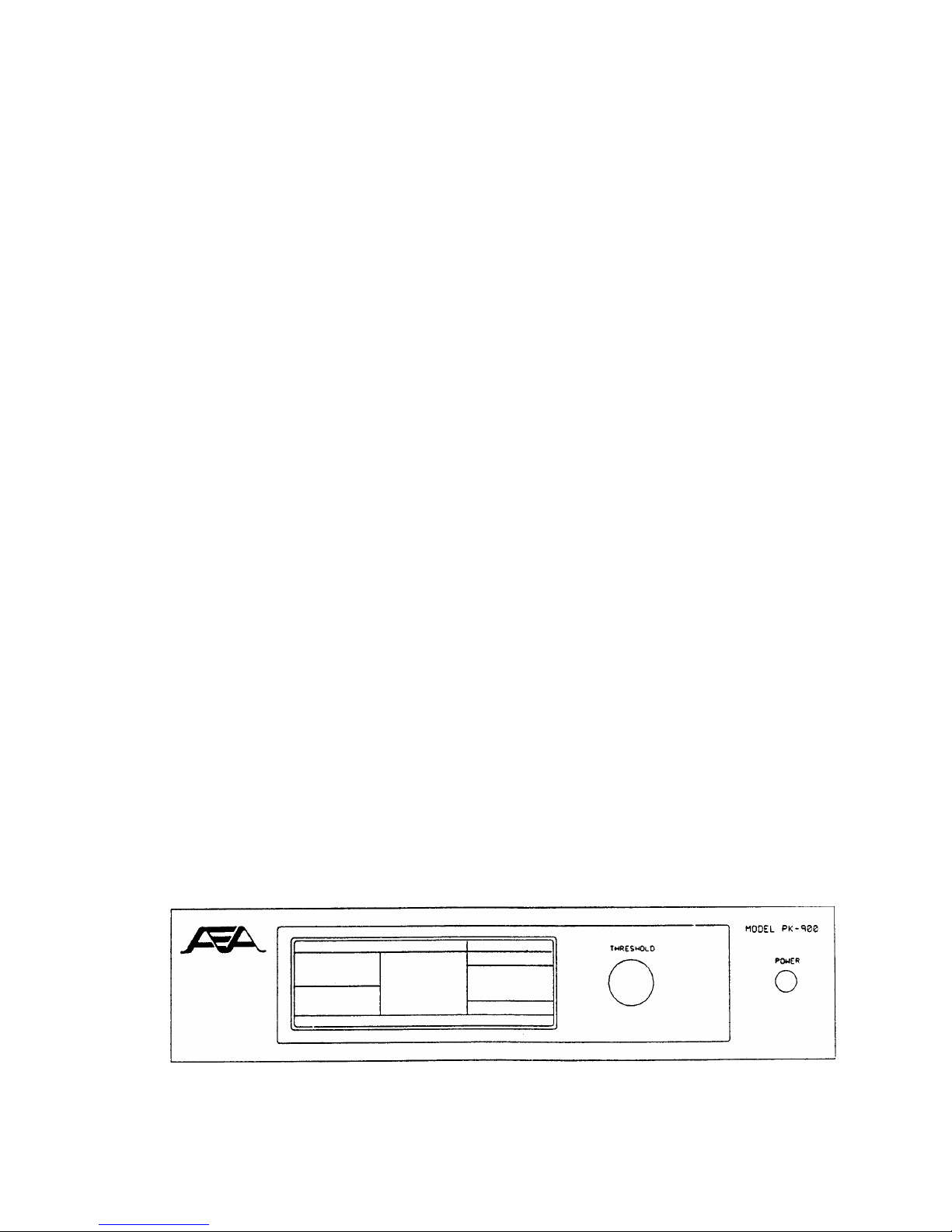
1.4.4 Controls and Indicators
Front Panel Indicators: Twenty-segment, selectable display
type: discriminator, magic eye or
zero center bargraph indicator for
tuning radio port 1.
Power Switch Front panel push-on push-off
Threshold Control Front panel knob controlling DCD
sensitivity of radio port 1 demodulator
Status Display LCD Status Display, with variable
intensity backlight, showing
Mode and data controller status
for both radio ports
1.4.5 General
Power Requirements: +13 VDC (12 to 16 VDC) at 1100 mA (max)
880 mA with LCD back light off
Mechanical: Overall, W 11 13/16" x D 12" x H 3.1/2"
(300 mm X 305 mm X 89 mm)
Weight 6 pounds 4 oz. (2.84
kilograms)
1/93 1-4

CHAPTER 2
COMPUTER INSTALLATION
2.1 Overview
In this chapter we will connect the PK-900 to the RS-232 Serial port
of your Computer or Computer Terminal. After the Serial connection
has been made we will perform a quick check of the internal software.
Finally we will check the PK-900's modem by performing a Packet
"loop-back" test. When you have completed this chapter, you will be
ready to connect the PK-900 to your receiver or transceiver and
begin using it on the air.
2.1.1 Equipment Required
You will need the following for this chapter:
o your PK-900 Data controller;
o a 13.6-volt DC, 1.5-amp (or greater) regulated power supply such
as those sold by Radio Shack (or a Timewave AC-5 or AC-4);
(the power supply must be able to supply at least 13 VDC to the
PK-900 while it is operating under load)
o the included PK-900 DC power cord unless the AC-4 is used;
o your Computer or Computer Terminal;
o a Communications or Terminal Emulation program for your computer;
(not needed if a Computer Terminal is being used)
o the included RS-232 cable with a 25-pin "D" connector on each
end;
o one of the included 5-pin shielded "radio cables";
(note that the radio cables may arrive as a single 10-ft. cable
which should be cut in half producing two 5-ft. cables.)
o The two, wire "Loop-back" jumpers necessary for testing;
o wire cutters and strippers or a small pocket knife, a small
straight-blade screwdriver and a medium Phillips-head screwdriver.
2.2 Unpacking the PK-900
Carefully remove the PK-900 from the box and its plastic bag.
Inspect the unit for signs of damage that may have occurred in
shipping. If there is visible damage, please contact the dealer or
shipper. Do not attempt to install or use a damaged PK-900.
We will be discussing some of the Controls, Indicators and
Connections in this installation so take a few moments to
familiarize yourself with them. The figures on the next pages may
help with their locations.
1/93 2-1
2.2.1 Connecting Power
MAKE SURE YOUR POWER SUPPLY IS OFF AND UNPLUGGED BEFORE WIRING
1. If you are using the AEA AC-4 or Timewave AC-5, skip to 5.
Otherwise, locate the PK-900 Power Cable in the accessory bag
. Strip off just enough insulation from the ends to connect it to
your 13-14 Volt DC regulated power supply.
2. The Center pin of the coaxial power plug is POSITIVE. Connect
the lead with the White stripe to the POSITIVE (+) lead on your
power supply. Check this with an Ohm-meter if you have one.
3. Connect the solid Black (GROUND) lead to the NEGATIVE (-) lead of
your power supply.
4. Connect the power plug to the 13 VDC Power Receptacle on the left
rear of the PK-900. DO NOT CONNECT YOUR COMPUTER YET.
5. Plug in your power supply or AC-4 and turn on power. Turn on
the PK-900 by depressing the Power Switch on the front of the
unit. At power-on, the LCD Status display on the left should
light. At this point, turn OFF the PK-900 and move on to
section 2.3.
If the Status display does not light, then re-check the above steps to
insure that 12-14 VDC is available at the power plug and the center
pin is POSITIVE.
If the Status display lights, and status indicators other than the
DCD indicators are displayed, then the PK-900 has already been
initialized. If the PK-900 has been initialized it is ready to
communicate with a computer or terminal at a specific baud rate
(probably 300, 1200, 2400, 4800 or 9600 baud). If you know what
this baud rate is then you should continue with the installation at
section 2.3 keeping this in mind.
If you do not know the baud rate the PK-900 has been initialized to
then you should reset the PK-900 by holding the rear-panel RESET
switch at the same time you turn on the power switch. After this is
done, no status indicators on the LCD Status display should be on
with the possible exception of either or both of the two DCD
indicators.
If the above did not produce the blank status indication, (ignoring
the DCD indicators) contact the Timewave Technical Support Department
as described in the front of this manual.
Figure 2-1 PK-900 Front Panel Controls and indicators
1/93 2-2
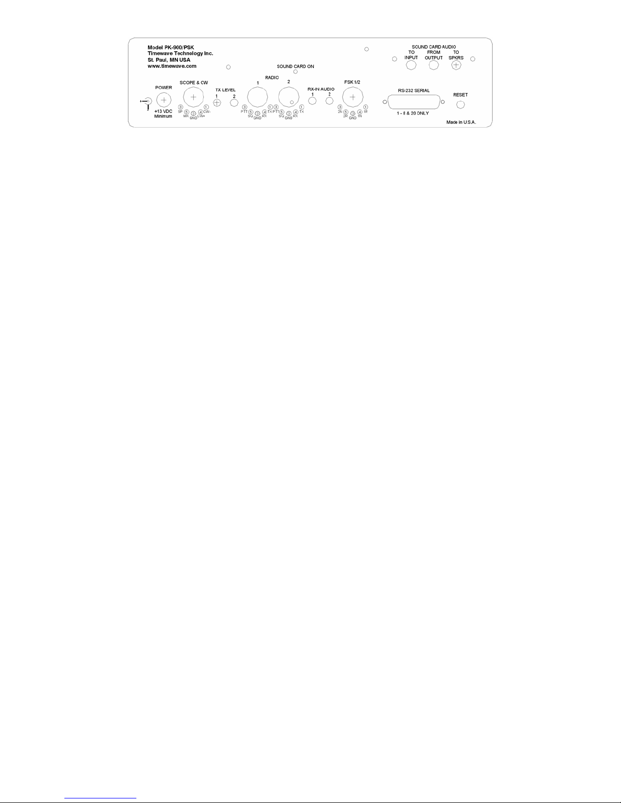
Figure 2-2 PK-900 Rear Panel Connections and Controls
2.3 Connecting Your Computer or Computer Terminal
MAKE SURE THE PK-900 AND YOUR COMPUTER ARE SWITCHED OFF
o Locate the PK-900 Serial Cable. Connect the 25-pin Female
connector to the RS-232 connector on the PK-900 rear panel.
o Connect the other end of this cable (Female DB-25) to the RS-232
Serial Port of your personal computer or Computer Terminal.
Details on connecting to common machines are listed below.
NOTE: This cable was designed to connect directly to a 25-pin IBM-PC
compatible RS-232 port. Many machines on the market today support
this configuration. Some less-common machines are listed in section
2.6. Please be certain you have properly connected the PK-900 to
your RS-232 computer or Terminal then proceed to section 2.4.
2.3.1 IBM-PC/XT/AT and Compatibles
IBM compatible 25-pin RS-232 serial ports should connect directly to
the supplied serial cable. Some IBM compatible machines are equipped
with a 9-pin serial port. For these machines a DB-9 to DB-25 adapter
should be obtained from a Radio Shack store or a computer dealer.
2.3.2 Apple Macintosh Series of Computers
AEA presently sells the program MacRATT with FAX which contains the
serial cable for the newer models of the Macintosh (models Mac + and
later). If you intend to use another communications program with the
PK-900 a Modem adapter cable must be purchased from your Apple
dealer to connect the Mac to your PK-900. For the newer machines
such as the Mac +, Mac SE and Mac II, a mini-8 to DB-25 adapter cable
is required (included with the AEA MACRATT with FAX program). For the
older Mac 128 and 512 machines, a DB-9 to DB-25 adapter cable from
your Apple dealer is needed.
2.3.3 Commodore 64 and 128 Computers
The Commodore 64/128 computers do not have an RS-232 port as standard
equipment. For these machines RS-232 adapters are available from
manufacturers such as Commodore or OMNITRONIX. These may work with
modem or terminal programs for your Commodore. Section 2.4 of this
chapter deals more with programs for personal computers. The AEA
Program COM-PAKRATT With FAX is NOT recommended for the PK-900.
1/93 2-3

2.3.4 Computer Terminal
If you have an RS-232 Computer Terminal, sometimes called a Dumb Terminal, Smart-Terminal or ASCII-Terminal, you may need to change the
gender of the cable provided with your PK-900. This can be
accomplished with an inexpensive double-male RS-232 gender changing
adapter available from Radio Shack and other computer dealers. The
Radio Shack part number is 26-243.
2.4 Setting Up Your Communications or Terminal Software Program
If you will be using your PK-900 with a Computer, you will need to
read parts of this section to set up your Communications or Terminal
Software. If you will be using your PK-900 with a Terminal you will
not need any software and may skip to section 2.5.
Setting up a communications program for your PK-900 is very
important. How your screen looks when you use your PK-900 depends
completely on your Communications program. AEA currently makes
available programs for the IBM-PC and compatibles and the Apple
Macintosh computers. These products are customized for radio
communications and are available at extra cost from your AEA
dealer.
The PK-900 operates in much the same manner as a telephone modem and
most modem Terminal Programs will control a PK-900 quite nicely.
Some of these programs are "Public Domain" which means they are FREE.
Other Terminal Programs are "Share-ware" which means you may get them
from a friend and try them before you buy them. Whether you are using
an AEA program or one of your own choosing, see the section below for
the particular type of computer you plan to use.
2.4.1 Terminal Programs for IBM PCs and Compatibles
Although you can use almost any terminal program with your IBM PC or
close compatible, AEA currently sells the PC-PAKRATT II w/FAX program
which provides many features not available in "telephone modem"
programs. See your AEA dealer for information on PC-PAKRATT II w/FAX.
If you already have the PC-PAKRATT II program, follow the program
manual and install the software on your computer. You should also
read through the PACKET OPERATION chapter of the PC-PAKRATT II manual.
Familiarity with Packet operation of PC-PAKRATT will be necessary for
performing a quick-check of the PK-900 in section 2.5 of THIS
manual.
As we mentioned above, an AEA program is not required to use the
PK-900. Many terminal programs can be found throughout the amateur
radio community or can be downloaded from Compuserve, GEnie and from
many telephone bulletin boards.
A partial list of PC programs tested with the PK-900 includes:
PROCOMM, CROSSTALK-XVI, SMARTCOMM, RELAY, BITCOM, QMODEM, PC-TALK,
CTERM, HAMCOM, HAMPAC, YAPP and the terminal program included with
Microsoft Windows 3.0 (tm).
1/93 2-4

Follow the installation directions that come with the Terminal
program you wish to use. Once installed on the computer, you
should start the program and set the communication parameters for
the following:
Data Rate = 1200 bits per second (Bauds)
Data bits = 7
Parity = EVEN
Stop bits = 1
Once these settings have been achieved and the correct serial
communications port chosen, you may proceed to section 2.5.
2.4.2 Terminal Programs for the Apple Macintosh
Although you can use almost any terminal program with your Macintosh,
AEA presently sells the MACRATT with FAX program which provides many
features not available in "telephone modem" programs. See your AEA
dealer for information on MACRATT with FAX.
If you already have the MACRATT program, please follow the program
manual and install the software on your Mac. You should also read
through the PACKET OPERATION chapter of the MACRATT manual.
Familiarity with Packet operation of MACRATT will be necessary for
performing a quick check of the PK-900 in section 2.5 of THIS
manual.
As we mentioned above, an AEA program is not required to use the
PK-900. Many terminal programs can be found throughout the amateur
radio community and can be downloaded from Compuserve, GEnie and from
many telephone bulletin boards.
A partial list of Mac programs tested with the PK-900 includes:
MAC TERMINAL, RED RYDER, MICROPHONE, SMARTCOMM II and MOCK TERMINAL
Follow the installation directions that come with the Terminal program
you wish to use. Once installed on the computer, you should start the
program and set the communication parameters for the following:
COMPATIBILITY:
1200 bauds, 7 bits/character, even parity, Handshake XON/XOFF,
FULL-DUPLEX, Modem connection, "telephone" port.
Once these settings have been achieved, proceed to section 2.5.
2.4.3 Terminal Programs for the Commodore 64, 64C and 128
Although AEA presently sells the COM-PAKRATT with FAX program package
for the PK-232, this program cannot access all the features of the
PK-900. AEA therefore cannot recommend using the COM-PAKRATT
package with the PK-900. If you already have this package, it will
certainly get you started with the PK-900 by using the "Dumb
Terminal" mode. You may wish to find another program which provides
more features than are available in the COM-PAKRATT program in the
Dumb Terminal Mode. Other ideas for terminal programs for the
Commodore-64 series of computers are listed below.
1/93 2-5

Many terminal programs can be found throughout the amateur community
or can be downloaded from Compuserve and from many telephone
bulletin boards. In addition a BASIC communications program is
listed in the Programmer's Reference Guide published by Commodore.
Use the program listing for "True ASCII". We suggest you operate
your PK-900 at 300 bauds with these computers to avoid possible
speed difficulties.
Follow the installation directions that come with the Terminal program
you wish to use. Once installed on the computer, you should start the
program and set the communication parameters for the following:
Data Rate = 300 bits per second (Bauds)
Data bits = 7
Parity = EVEN
Stop bits = 1
Once these settings have been achieved, proceed to section 2.5.
2.5 System Startup and Loop-back Test
Make sure that you have connected your PK-900 to a 12-14 Volt DC
power source and to the RS-232 port of your computer or Terminal.
If you are using a computer, you must also have a communications
program and be familiar with its operation. You are now ready to
begin the following PK-900 Startup and Loop-back test procedure.
1. Don't connect any cables to your radio yet!
2. Remove the 16 gauge wire "Loop-back" connectors from the
PK-900 accessory bag.
3. Plug these into pins 1 and 4 of each of the radio connectors on
the PK-900's rear panel.
4. Set both AFSK levels on the back panel of the PK-900 to 50%
rotation (straight up and down) using a small screwdriver.
5. Turn on your computer. Load and run your communications program.
If you are using an AEA PAKRATT program, follow the program
instructions to enter the Packet mode, then skip to step 11.
If you are using another Terminal Program or a Computer Terminal,
Set your computer's terminal program to:
o 1200 bauds (if available);
o seven-bit word;
o even parity;
o one stop bit.
NOTE: You may use other terminal baud rates with the PK-900 - we
recommend 1200 baud here to keep this procedure easy and consistent.
6. Press the PK-900's power switch to the ON position.
At power-on, the LCD Status display on the left should light,
1/93 2-6

showing either no status indications or one or both of the DCD
indicators. If the Status display lights and other status
indicators are displayed, then the PK-900 has already been
initialized. If you know the terminal baud rate the PK-900 has
been set to, you may proceed to step 11; otherwise you must
reset the PK-900 as described below.
To reset the PK-900, simply hold the rear-panel RESET switch in
at the same time you turn on the power switch. After this is
done, then the only LCD Status indicators showing may be the DCD
indicators. If your serial port is operating at 1200 bauds as we
recommend, you'll see the "autobaud" message:
Please type a star ( * ) for autobaud routine.
If your serial port is operating at 300, 2400, 4800 or 9600
bauds, you may see some "garbage" characters.
This is normal and you should proceed with step 7.
7. Type an asterisk (*). When the PK-900 has "recognized" your
computer's data rate, the CMD LCD will light. Your screen will
then display the sign-on message:
PK-900 is using default values.
AEA PK-900 Data Controller
Copyright (C) 1986-1993 by
Advanced Electronic Applications, Inc.
Release DD.MMM.YY
cmd:
Make note of the Release date on the first page of this manual.
This is important should you ever call AEA for technical support.
It should match the firmware release sticker on the bottom of
your PK-900.
8. If you are using an AEA program, follow the instructions in the
program manual to enter the packet callsign (MYCALL) of AAA into
the PK-900. Even though this is not your callsign, please do
this for this procedure. You must change it to YOUR OWN CALLSIGN
after completing this procedure.
If you are using a Computer Terminal or a non-AEA terminal
program the following will set your packet callsign to AAA:
Enter MYCALL by typing MY AAA <Enter> (or <RETURN>).
(<RETURN> or <Enter> means type the single key on your keyboard.)
Your monitor should display:
MYcall was PK900/PK900
MYcall now AAA/PK900
9. If you are using an AEA program follow the instructions to
CONNECT in packet mode to AAA. Since you have just entered your
callsign as AAA, you will connect to yourself.
If you are using a Computer Terminal or a non-AEA program,
1/93 2-7

entering the following after the "cmd:" command mode prompt
will cause the PK-900 to Connect to AAA:
C AAA <Enter>
After a few moments, your monitor should display:
*** CONNECTED to AAA
10. Type HELLO SELF <Enter>
After a few moments, your monitor should echo the same message.
If you have gotten this far then the digital section of the
PK-900 and the VHF packet modem of port 1 are both working.
11. We will now check the PK-900's HF modem. If you are using an
AEA program, follow the instructions to select the HF modem by
turning the VHF Parameter OFF; this will automatically set the
radio baud rate HBAUD to 300 for HF packet work.
If you are using a Computer Terminal or a non-AEA terminal
program, the following sets the HF mode of the PK-900:
Type <CONTROL-C>. (Type C while pressing the <Ctrl> key down.)
Your monitor should respond with the command prompt:
cmd:
Then enter VHF OFF <Enter>
Your monitor should respond with:
Vhf was ON/ON
Vhf now OFF/ON
Then enter HB 300 <Enter>
Your monitor should respond with:
HB was 1200/1200
HB now 300/1200
12. If you are using an AEA program type HELLO SELF <Enter>
Your monitor should soon echo the message you've just typed.
If you are using a Computer Terminal or a non-AEA terminal
program, you must first type CONV or K followed by a <Enter>.
Now you may type a few characters. Your monitor should soon echo
the characters you've just typed.
13. If you are using an AEA program, follow the instructions to
DISCONNECT from a Packet station.
If you are using a Computer Terminal or a non-AEA terminal
program the following will cause the PK-900 to DISCONNECT:
1/93 2-8

Enter <CONTROL-C>
Your monitor should respond with the command prompt:
cmd:
Enter D <Enter>
Your monitor should respond with:
cmd:*** DISCONNECTED: AAA
p1 AAA*>AAA (UA)
If all of the above steps were successful, you've completed the quick check and are ready to proceed to Chapter 3. In Chapter 3 you will
connect your PK-900 to your radio and begin using it "on the air".
If you have problems with the steps shown above, go back to Step 1
AFTER checking all cables and connectors. Read each step again
carefully. The most common problems are trying to connect to a call
different from AAA, not having the "loopback" jumpers in the
correct pins, or not setting the AFSK levels to 50% rotation.
If you still have problems, leave your PK-900 ON and contact AEA's
Technical Support Department as suggested in the front of this manual.
2.6 Detailed RS-232 Connections for Other Computers
If the type of computer you plan to use with the PK-900 was not
mentioned in the beginning of this chapter, you may find specific
connection information in the sections below. You will also need a
Communications program to use with your computer which AEA can not
provide. See section 2.7 for information regarding Communication
programs for many of these machines.
Some computers require a serial port adapter card that incorporates
the necessary RS-232-C interface circuitry. The IBM-PC and Apple II
series of computers are good examples of this.
Computers that do not have a serial port or do not permit use of a
suitable adapter or level converter cannot be used with the PK-900.
2.6.1 Apple II Series
The Apple II, II+ and IIe computers require an RS-232 Serial card to
connect to your PK-900. The most popular we know about is the
Super-Serial Card which should be available from your Apple dealer.
2.6.2 Commodore C-64, C-128 and Vic 20
Commodore, OMNITRONIX and other manufacturers sell a signal level
converter that is installed in the User Port Connector on the rear of
the computer. The converter changes the computer's internal TTL
voltage levels to the proper RS-232-C voltage levels and polarities.
2.6.3 IBM PCjr
The PCjr uses standard RS-232-C voltage levels; however, the
1/93 2-9

connector is not standard and is hard to find. Pin-out information
can be found in the IBM PCjr Technical Reference Manual. Some
dealers sell a 'IBM PCjr Adapter Cable for Serial Devices' that
converts the connector on the PCjr to standard RS-232-C. The
cable attaches between the PCjr and the PK-900 Serial Cable.
2.6.4 Tandy Color Computer
The CoCo series (except for the Micro CoCo) uses a four-pin DIN
connector for its serial interface. Wire a cable as shown below. All
necessary parts should be available from your Radio Shack dealer.
CoCo PK-900 (DB25P)
4 ..................... 2
2 ..................... 3
3 ..................... 7
2.6.5 Tandy Model 100/102 and NEC 8201
The Model 100/102 and NEC 8201 have built-in standard RS-232 serial
ports which are compatible with the PK-900. You'll need a DB-25
male-male gender changing adapter to use the supplied PK-900 Serial
Cable.
2.6.6 Other Computers with RS-232-C Ports
If your computer has an RS-232 port, consult your computer manuals to
see which pins are used for Transmit-Data, Received-Data and Signal Ground. Read the manufacturer's recommendations for connecting the
serial port to a modem and connect your PK-900 in the same way.
Your PK-900 is configured as Data Communications Equipment (DCE)
which receives data on pin 2 of the 25-pin DB-25 connector or pin 2
of the 25 pin cable supplied with the unit. Most computers and
terminals are configured as Data Terminal Equipment (DTE)
transmitting data on pin 3 of a DB-9 or pin 2 of a DB-25 RS-232
connector.
o If your computer is configured as DTE:
Use the supplied RS-232 cable with a Gender changing adapter if
necessary. These are available from Radio Shack (Part # 26-243)
and other computer stores.
o If your computer is configured as DCE:
You may want to purchase a Null Modem adapter from Radio Shack
(Part # 26-1496) or other computer store.
You may also wire your own cable directly to the PK-900's DB-25
connector by wiring the Transmit Data (TXD), Receive Data
(RXD), and the Signal Ground (GND) to a DB-25P (Male)
connector as diagramed below:
1/93 2-10

Computer PK-900 (DB25)
TXD .......................... 2
RXD .......................... 3
GND .......................... 7
o As a default the PK-900 provides XON/XOFF software flow-control
to the computer or terminal. The command XFLOW can be
turned OFF to enable hardware handshake if your computer
requires it.
Hardware flow control is achieved with RTS/CTS (pins 4 and 5)
of the 25-pin connector on the PK-900's rear panel.
2.6.7 Other Computers with Non-Standard Serial Ports
Computers with non-standard serial ports must meet the following
conditions:
o The signal levels must be compatible with RS-232-C. The PK-900
requires the voltage levels from the computer be greater than +3
volts in the "asserted" state and 0 volts or less in the "non asserted" state.
o The signal polarity must conform to the RS-232-C standard. The
0 or negative-voltage state must correspond to logical "1" and
the positive-voltage state to logical "0."
o The computer must be able to correctly receive a signal that
meets asynchronous RS-232-C specifications. The PK-900
supplies signals that meet this specification.
Make or buy a cable that provides the following connections:
o The computer's serial port signal ground or common pin must be
connected to pin 7 of the PK-900's 25-pin connector.
o The pin on which the computer SENDS data must be connected to
pin 2 of the PK-900's 25-pin serial connector.
o The pin on which the computer RECEIVES data must be connected to
pin 3 of the PK-900's 25-pin serial connector.
If your computer requires any other signals, you must arrange to
provide them. The PK-900 has the standard hardware handshake lines
available. As a default the PK-900 provides XON/XOFF software flow
control to the computer or terminal. The command XFLOW can be turned
OFF disabling software flow control and enabling hardware handshake if
your computer requires it. The documentation provided with your
computer or serial card should clarify any special requirements.
2.7 Terminal (Modem) Software for Other Computers
Any communications program that enables your computer to emulate or
act as an ASCII terminal with a telephone modem should work with
your PK-900. If you have a familiar program you have used
successfully, use it to communicate with your PK-900.
1/93 2-11

2.7.1 Terminal Programs for the Apple II, II+, IIe and IIC
The PK-900 operates well with the Apple II family of computers using
both Apple-supplied or third-party serial interface cards. Terminal
programs include Modem Manager, ASCII EXPRESS PRO, Hayes SMARTCOMM II,
and DataCapture 4.0.
2.7.2 Terminal Programs for the Commodore Vic 20
A BASIC communications program is printed in the VIC 20 Programmer's
Reference Guide published by Commodore. Use the program listing for
"True ASCII"; Commodore computers internally use a modified ASCII
format. We suggest you operate your PK-900 at 300 bauds with these
computers to avoid possible data speed difficulties.
2.7.3 Terminal Program for the IBM PCjr
The PCjr's BASIC cartridge contains a terminal program. Start the
program by typing TERM. Refer to the PCjr's BASIC manual for
details on the program. For best results with the PCjr do not run the
PK-900's serial port baud rate faster than 1200 bauds.
2.7.4 Terminal Programs for the Tandy Color Computer
Several terminal programs are available for the CoCo. We suggest
that you use a commercial program rather than writing your own. The
CoCo's "software UART" may be difficult to program in BASIC.
2.7.5 Terminal Program for the Tandy 100/102 and NED 8201
The Model 100, 102 and NEC 8201 have built-in terminal programs in
ROM which control the modem and the RS-232C port. Consult the
computer documentation for instructions in their use. Make sure that
you do not use the program to control the built-in telephone modem.
1/93 2-12
 Loading...