

Timewave PK-232SC Operating Manual
PK-232SC
Operating Manual
Note: This manual covers the features added with the SC version of the PK-232.
The main PK-232 manual describes the modes and features found in the
original PK-232 and PK-232MBX. They are marked with an “*”.
The DSP manual supplement describes the DSP board features.
1

WARRANTY TIMEWAVE TECHNOLOGY INC.
LIMITED ONE YEAR WARRANTY
WHO IS COVERED This warranty is extended only to the original purchaser of the A.06118.
WHAT WE WILL DO
If your A.06118 fails in normal use because of a defect in workmanship or materials
within one year of the date of purchase, we will repair or replace (at our option) the
equipment at our factory without charge to you. Timewave will pay for the return of the
warranty-repaired unit to you.
WHAT YOU MUST DO
First, double check your connections and operating procedure. If you're certain that the
unit is faulty, notify Timewave Customer Service immediately. If Timewave is unable to
resolve the problem by telephone or email, we will give you an RMA number and ask
you to return the unit. You must pay all shipping and insurance charges for returning the
unit to our factory.
WHAT IS NOT
COVERED
We cannot be responsible for damage caused by accidents, abuse, misuse, improper
installation, or unauthorized attempts to repair the unit. This warranty does not cover any
parts of the PK-232 except the A.06118.
SERVICE WARRANTY
Timewave service work performed in connection with this warranty is warranted to be
free from defects in materials and workmanship for 30 days from the date of repair. All
other terms of the limited warranty apply to the service warranty.
HOW TO CONTACT TIMEWAVE
Contact Timewave Customer Service by telephone at (651) 489-5080 or by FAX at (651)
489-5066.
Mailing and shipping address is: 27 Empire Drive, Suite 110, St. Paul, MN 55103
email: sales@timewave.com
techsupport@timewave.com
service@timewave.com
web: www.timewave.com
TIMEWAVE MAKES NO OTHER WARRANTY, EXPRESSED OR IMPLIED, INCLUDING BUT NOT LIMITED TO THE
IMPLIED WARRANTIES OF MERCHANTABILITY OR FITNESS FOR A PARTICULAR PURPOSE.
©2001, 2005, 2011 by Timewave Technology Inc., St. Paul, MN USA
2

Table of Contents
Overview ...................................................................................................................................... 4
PK-232SC Block Diagram ............................................................................................................. 5
Front Panel .................................................................................................................................. 6
Rear Panel .................................................................................................................................... 8
Operation .................................................................................................................................. 12
PC USB Connection .................................................................................................................... 12
USB device driver....................................................................................................................... 12
Power......................................................................................................................................... 12
Radio .......................................................................................................................................... 12
PK-232SC Ports .......................................................................................................................... 12
PK-232SC Control ....................................................................................................................... 13
Rig Control ................................................................................................................................. 13
USB Audio Sound Card .............................................................................................................. 13
SC Board Jumper Settings .......................................................................................................... 14
Data Sheet ................................................................................................................................. 15
3

Overview
The PK-232SC is the latest generation of multimode data controllers built upon the solid
foundation of the legendary PK-232. The PK-232SC features an expanded interface to
connect and control your radio transceiver, station accessories and computer.
The key to the new PK-232SC is a single USB cable from your PK-232SC to your
computer. No other connection is necessary. Note the PK-232SC block diagram in
Figure 1. The USB cable from the computer connects to a four port USB hub inside the
PK-232.
Port 1 of the USB hub connects to a dual USB-to-UART bridge.
One of the UART serial ports connects directly to the PK-232SC UART serial port. This
shows up on your computer as a standard COM port. Your software terminal program
connects to this COM port to control the PK-232SC.
The other UART serial port is the rig control port. This optically isolated port supports
Icom CI-V, Yaesu CAT, Kenwood logic level, and RS-232 connections. This shows up
on your computer as an enhanced COM port. Your software rig control program controls
your transceiver.
Port 2 of the USB hub connects to a USB Audio sound card inside the PK-232SC.
The sound card audio is transformer isolated from the USB circuitry. The sound
card/PK-232 switch or a software command selects either sound card transmit audio or
PK-232SC transmit audio. Receive audio from your transceiver is always connected to
both the sound card receive audio and the PK-232 receive audio.
Ports 3 and 4 of the USB hub connect to a dual USB jack on the back panel of the
PK-232SC. Use these jacks for rig control of USB-equipped transceivers and for other
USB station accessories.
A new feature in the PK-232SC is an instant reset switch. A quick flick of the switch
when the power is off resets the PK-232SC to factory default condition.
4
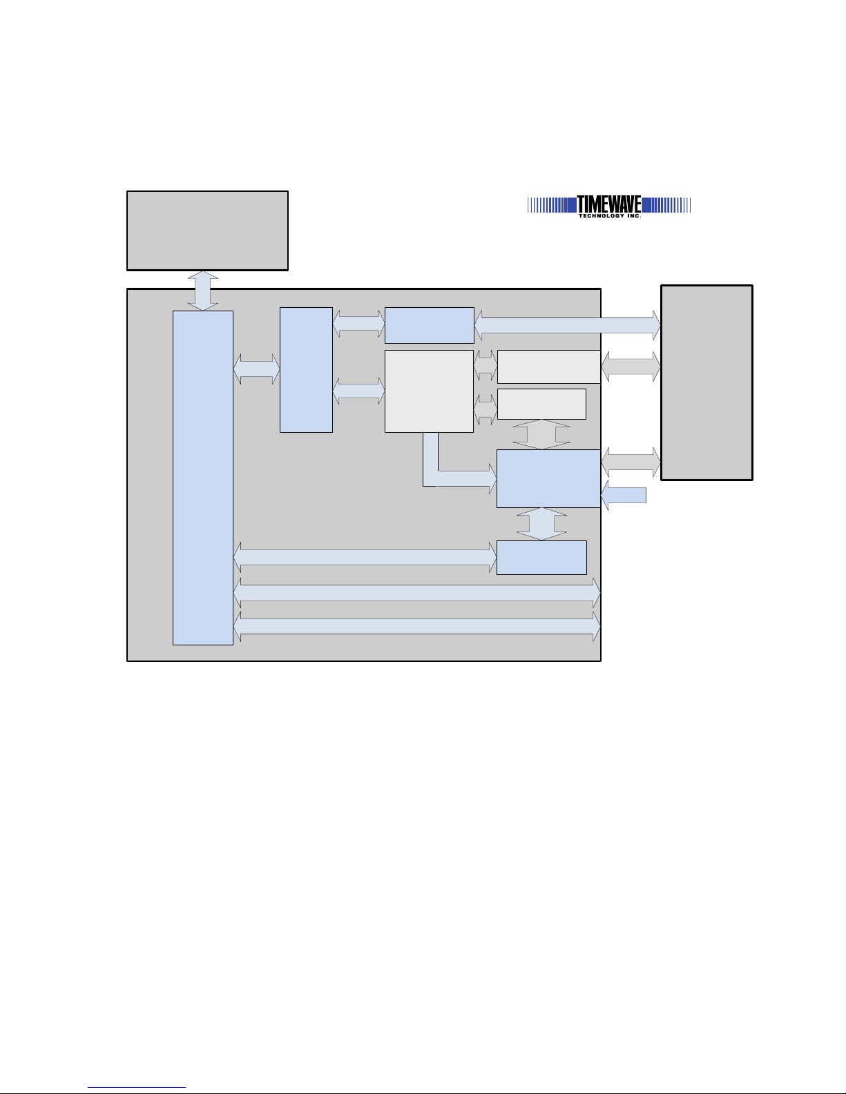
PK-232SC Block Diagram
Radio XCVR
Computer
PK-232 CPU
System Block Diagram
PK-232SC
Multimode Controller
USB
USB-Audio
Sound Card
USB
Audio switching
matrix
Data
Audio
Rig control data
Rig
Control
Serial Data
USB
Rig Control I/O
Serial data
USB
Hub
USB
PTT,
CW, FSK
Input
USB
to
UARTx2
USB
Control
PK-232SC
PK-232 Modem
Audio
SC
Data
Audio
Data Audio
PK-232
Data
Audio
PK-232 PTT, CW,
FSK Output
Aux USB Port
Aux USB Port
SC / TNC
Switch
SC / TNC
Switch
Figure 1
5
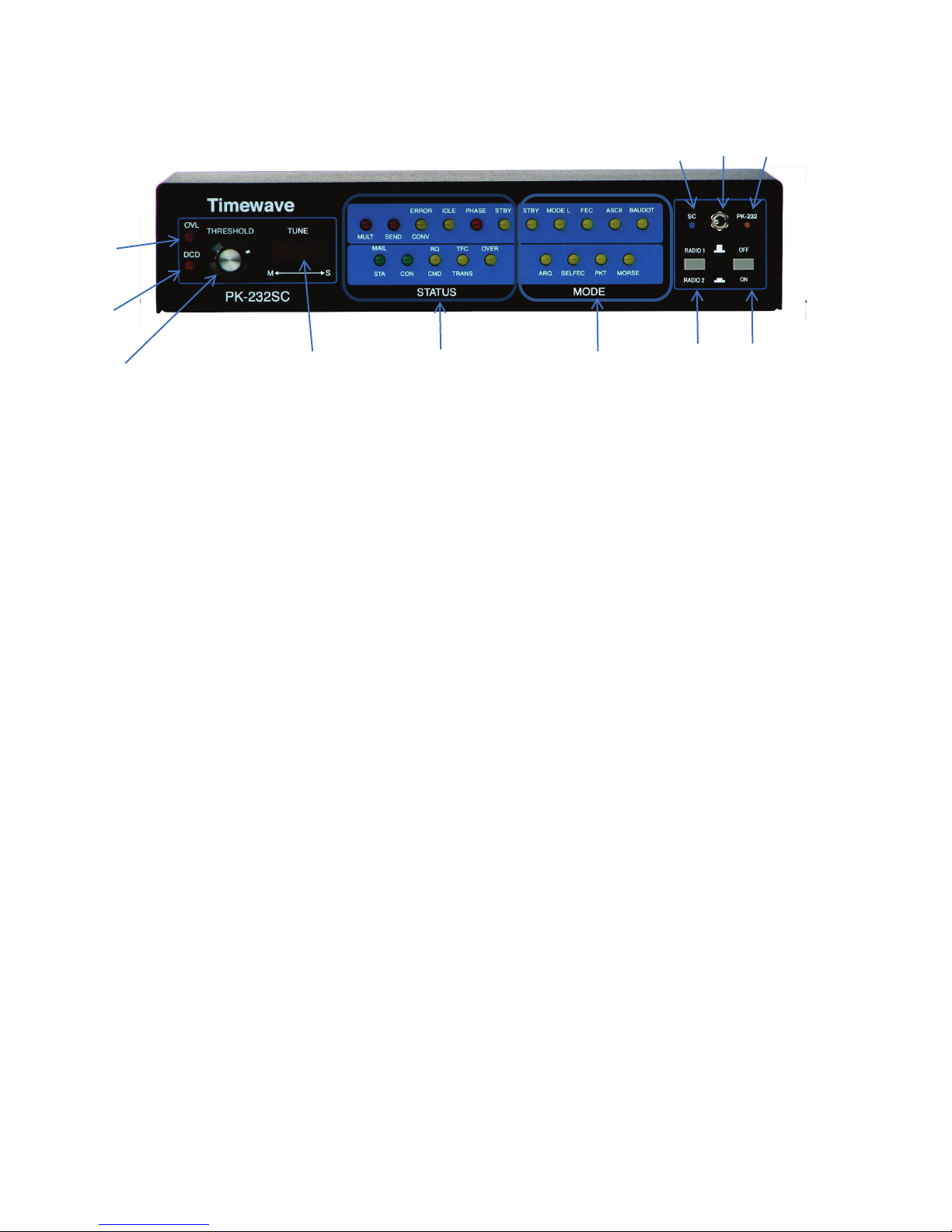
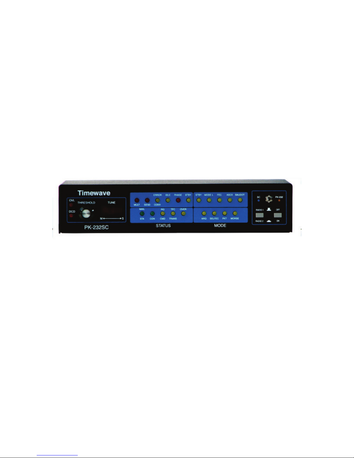
Front Panel
1
2
3
4
5
6
7
8
9
10
11
1. OVL LED
2. DCD LED*
3. THRESHOLD control*
4. TUNE LED bar*
M – Mark
S – Space
5. STATUS LEDs*
6. MODE LEDs*
7. RADIO 1 / RADIO 2 switch*
8. ON / OFF Power Switch*
9. SC LED
10. PK-232 LED
11. SC / PK-232 panel switch
1. Blue SC LED on – The SC mode is on if:
a) the switch is set to left
OR
b) Software has selected the SC mode (using SC command sequence)
6

2. Amber PK-232 LED on – The PK-232 mode is on if the switch is set to the
right.
3. If both blue and amber LEDs are on at the same time, you have selected
the SC mode with software control and have set the panel switch to PK-232
mode.
The sound card mode (blue LED) is active if it is selected with either the panel
switch or the software control. The software control will override the front
panel switch PK-232 mode selection.
7
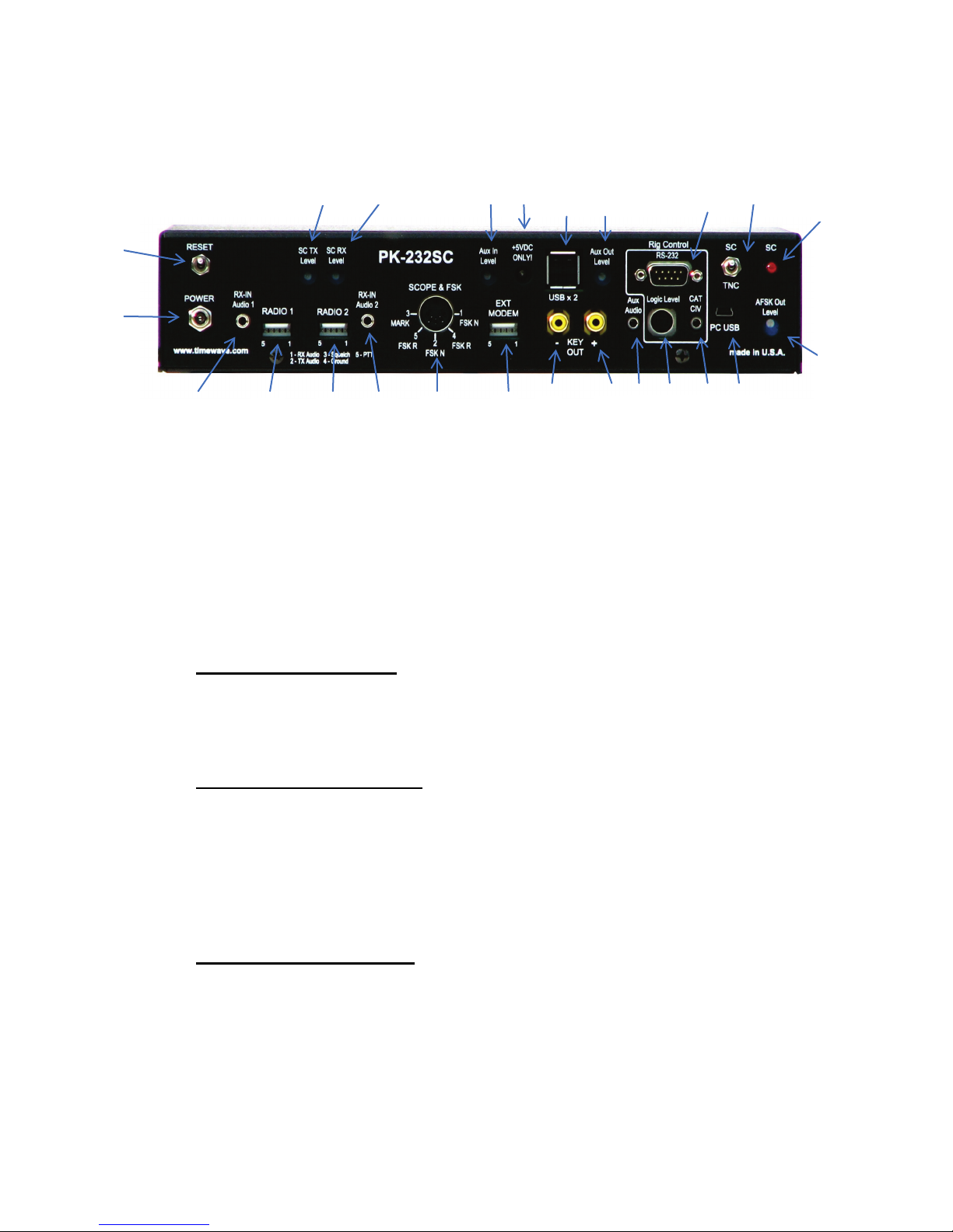
Rear Panel
3
4
5
6
7
8
1
2
10
11
12
13
14
15
16
17
18
19
22
21
20
24
23
9
1) Reset
Press once momentarily with power off.
2) Power
3) RX-IN Audio 1*
3.5 mm mono phone jack
4) Radio 1*
5) Radio 2*
Resets PK-232 to factory default (baudot mode, erases memory)
Power jack for +13.5 VDC @ 750 Ma. (5.5mm x 2.1mm)
Tip – receive audio from radio
Ring & Sleeve – Ground
Five pin IDC flat connectors
1 – receive audio from radio
2 – transmit audio to radio
3 –Squelch
4 – Ground
5 – PTT
Five pin IDC flat connector
1 – receive audio from radio
2 – transmit audio to radio
3 –Squelch
4 – Ground
5 – PTT
Ring – ground/shield
8
 Loading...