

Timewave DSP-9 Operating Manual

DSP-9
Audio Noise Reduction Filter
Operating Manual
Timewave Technology Inc.

Table of Contents
1. Introduction to the DSP-9 ......................................................... 2
2. Specification ............................................................................... 3
3. Installation .................................................................................. 4
4. Operation .................................................................................... 5
5. Troubleshooting .......................................................................... 7
6. Warranty ..................................................................................... 7
7. Schematic Diagram ................................................................... 8
Copyright 1994 Timewave Technology Inc.
St. Paul, MN USA
(612) 452-5939
Rev. 2.00
1

1. Introduction to the DSP-9
The DSP-9 is an audio noise filter for amateur radio voice and CW operation. The DSP9 filters and reduces noise and interference to improve radio reception. The DSP-9 uses
digital signal processing technology to implement algorithms that perform three basic
filter functions: 1) Random noise reduction, 2) Adaptive multi-tone notch filtering
(Tone noise reduction) and 3) Bandpass filtering. Push-button switches permit
simultaneous selection of the three functions.
RANDOM/TONE NOISE REDUCTION
The noise reduction functions of the DSP-9 operate by examining a characteristic of signals and
noise called correlation, and dynamically filtering out the undesired signals and noise. The
degree of correlation is relative. Random noise such as white noise or static is uncorrelated.
Speech is moderately correlated. Repetitive noise such as a heterodyne is highly correlated.
The DSP-9 measures correlation and filters out signals and noise that are outside its correlation
thresholds. There is little degradation of the desired speech signal. The amount of noise
reduction varies according to the correlation characteristics of the noise. Typical noise reduction
ranges from 5 dB to 20 dB for random noise and up to 50 dB for heterodynes.
BANDPASS FILTERS
The DSP-9 has bandpass filters that are used in voice and CW modes. In a typical example of a
voice mode application, a bandpass filter can improve a signal with a poor signal-to-noise ratio.
A bandpass filter removes the high and low audio frequency components that do not contribute
significantly to the speech intelligibility, thus improving signal qualitity. Another common
voice mode example is the improvement of a SSB signal corrupted by adjacent channel
interference (QRM). The steep skirts of the bandpass filters allow the interference to be
eliminated with minimal effect on the desired signal. In the voice mode, two front panel push
buttons select one of three voice bandpass filter bandwidths from two sets of filters. An internal
jumper behind the back panel selects the filter set, either 1.6, 2.0, and 2.4 kHz., or 1.8, 2.4, and
3.1 kHz.
CW signals require Bandpass filters with steep skirts and linear phase response. Linear phase
response maximizes the usable signaling rate for a given bandwidth and minimizes ringing often
heard on extremely sharp filters. The DSP-9 has six different CW filters with skirts so steep that
a signal literally falls off the edge of the pass band as you tune through a CW signal. The
bandwidths of these filters range can be selected at either 500, 200 or 100 Hz. The center
frequency for the CW Bandpass filters can be either 600 or 750 Hz. The narrow filters are
useful for trying to dig out extremely weak signals from the noise and QRM. The wider filters
allow easy tuning and listening to multiple CW signals simultaneously.
2

2. SPECIFICATION
AUDIO INPUT
Impedance 22 Ohms default setting or 10,000 Ohms, jumper slectable
AUDIO OUTPUT
Speaker output power 1.6 watts into 8 ohms at 13.8 VDC
Distortion less than 1% at rated output
VOICE FILTERS
Random Noise Reduction entire freq. range of Up to 20 dB, varies with Adaptive 10 ms max.
Tone Noise Reduction entire freq. range of Up to 50 dB, varies with Adaptive 10 ms max.
(automatic notch) selected Bandpass filter noise characteristics
3.2 watts into 4 ohms at 13.8 VDC
Frequency range Attenuation Type Delay
selected Bandpass filter noise characteristics
Bandpass - Voice 300 Hz - 3.4 kHz, 60 dB at 180 Hz FIR Linear 10 ms max
Note: The random noise reduction, tone notch and voice Bandpass filters can operate simultaneously.
CW FILTERS
Bandpass - CW Bandwidth = 100 Hz, 60 dB at 50 Hz FIR Linear 30 msec max
Random Noise Reduction entire freq. range of Up to 20 dB, varies with Adaptive 10 ms max.
Note: The random noise reduction and CW Bandpass filters can operate simultaneously.
SIGNAL PROCESSING
A-D/D-A Converter 16 bit linear, sigma-delta conversion
Signal Processor 16 bit, 81ns Analog Devices ADSP-2105
CONTROLS
FRONT PANEL REAR PANEL
Volume/power on-off Audio In put Phono jack - RCA style
Bypass switch Speaker Audio Output Phono jack - RCA style
Voice/CW switch Power In 5.5 mm / 2.1 mm power jack (center pin positive +)
Random Noise Reduction
Tone Noise Reduction
Filter bandwidth (2)
Overload LED (red)
Normal LED (yellow)
300 Hz - 2.7 kHz, outside the passband phase
and 300 Hz - 2.1 kHz,
or (jumper selectable)
300 Hz - 2.7 kHz,
300 Hz - 2.3 kHz,
and 300 Hz - 1.9 kHz
200 Hz and 500 Hz. outside the passband phase
Center freq. = 600 Hz. & 750 Hz. ,
or (jumper selectable)
400 Hz. & 500 Hz.
selected Bandpass filter noise characteristics
DIMENSIONS
Size 6.0 in. wide x 6.0 in. deep x 1.75 in. high (153 mm wide x 153 mm deep x 45 mm high)
Weight 2 lb. (0.9 Kg.)
POWER
12-16 VDC @ 1000 ma
3
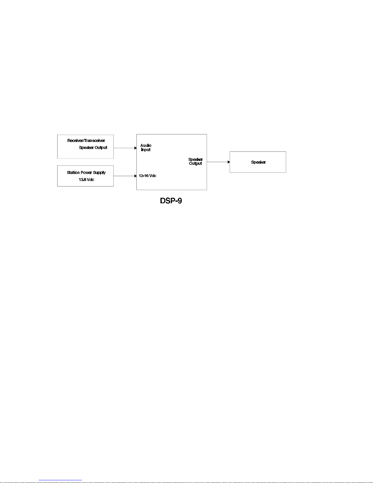
3. Installation
To install a DSP-9 in a station, an operator must provide power to the DSP-9 and make
audio input and output connections to the DSP-9. A typical DSP-9 installation is shown
below in Figure 3.1.
Figure 3.1
POWER SUPPLY
The DSP-9 requires a power source of 12 to 16 Volts dc. at 1.0 Amperes.
of the power connector is POSITIVE (+).
The center pin
Acceptable power sources include:
• 13.8 volt dc. transceiver power supply (recommended power source for the DSP-9
because it is better regulated than most plug-in wall outlet supplies). Note that some
transceivers with internal power supplies have accessory power jacks with insufficient
current output.
• Radio Shack 273-1653 12 V.d.c. @ 1 Ampere plug-in wall supply
Switching power supplies are generally
Connecting Cables
Shielded coaxial cables with RCA phono connectors should be used to minimize the
possibility of RF interference to the DSP-9. Timewave recommends coaxial video cables
with metal adapters to match the connectors on transceivers and speakers.
on the DSP-9 audio input connector must not be connected to the transceiver speaker
ground.
AUDIO INPUT
The audio input of the DSP-9 is an RCA phono connector on the rear panel of the DSP-9.
Matching the output level of the radio to the input level of the DSP-9 is necessary to take
not
recommended.
The center pin
4
 Loading...