

Page 1

DSP-59+
Audio Noise Reduction Filter
Operating Manual
Manual Version 3.1S
Timewave Technology Inc.
Page 2

Table of Contents
1. Introduction to the DSP-59+ 2
2. Description of Controls and Connectors 2
3. Specification 5
4. Installation 7
5. Operation 9
6. Troubleshooting 16
7. Warranty 19
8. Electromagnetic Interference 20
9. Schematic Diagram 20
10. Appendix - Connector Requirements24
Copyright 1994, 1995 Timewave Technology Inc.
St. Paul, MN USA
(612) 452-5939
Manual Rev. 3.1, 27 June 1995
1
Page 3

1. Introduction to the DSP-59+
The DSP-59+ is an audio noise filter for amateur radio voice, data and CW operation.
The DSP-59+ filters and reduces noise and interference to improve radio reception.
The DSP-59+ uses digital signal processing technology to implement algorithms that
perform four basic functions: 1) Random noise reduction, 2) Adaptive multi-tone notch
filtering (Tone noise reduction), 3) Bandpass/Highpass/Lowpass filtering, and 4) RTTY
remodulation.
Random/Tone Noise Reduction
The noise reduction functions of the DSP-59+ operate by examining a characteristic of
signals and noise called correlation, and dynamically filtering out the undesired signals
and noise. The degree of correlation is relative. Random noise such as white noise or
static is uncorrelated. Speech is moderately correlated. Repetitive noise such as a
heterodyne is highly correlated. The DSP-59+ measures correlation and filters out
signals and noise that are outside its correlation thresholds. The amount of noise
reduction varies according to the correlation characteristics of the noise. Typical noise
reduction ranges from 5 dB to 20 dB for random noise and up to 50 dB for heterodynes.
Highpass/Lowpass Filters
The DSP-59+ has 15 highpass and 15 lowpass filters that are independently selectable
from front panel controls. There are many uses for the 225 combinations of highpass and
lowpass filters that the DSP-59+ offers. In a typical example of a voice mode
application, highpass and lowpass filters can improve a signal with a poor signal-to-noise
ratio. The independent highpass and lowpass filters remove the low and high audio
frequency components that do not contribute significantly to the speech intelligibility,
thus improving signal quality. Another common voice mode example is the
improvement of a SSB signal corrupted by adjacent channel interference (QRM). The
steep skirts of the highpass and lowpass filters allow the high side and low side
interference to be eliminated independently with minimal impact on the desired signal.
Although the DSP-59+ has bandpass filters for CW and the most common data modes,
the 225 selectable highpass and lowpass filter combinations also allow precise filtering
for modes such as wideshift RTTY. The DSP-59+ highpass filter adjustment range is
from 200 to 1600 Hz. and the lowpass range is from 1700 to 3400 Hz.
Bandpass Filters
The DSP-59+ has 316 bandpass filters that are used in data and CW modes. Narrow
band signals like CW and RTTY require bandpass filters with steep skirts and linear
phase response. Linear phase response maximizes the usable signaling rate for a given
bandwidth and minimizes ringing often heard on extremely sharp filters. The DSP-59+
has 195 CW filters with skirts so steep that a signal literally falls off the edge of the
passband as you tune through a CW signal. Bandwidths for these filters range from 25
Hz. to 600 Hz., and center frequencies from 400 to 1000 Hz. The narrow filters are
useful for trying to dig out extremely weak signals from the noise and QRM. The wider
filters allow easy tuning and listening to multiple CW signals simultaneously. Three
2
Page 4

optional CW center frequencies may be internally programmed for older Collins KWM-2
and S-Line equipment.
The DSP-59+ also has 12 RTTY, AMTOR, PACTOR, G-TOR and HF packet bandpass
filters centered at 2210 Hz. One of five optional center frequencies may be internally
programmed for other common operating modes such as European standards or 16001800 Hz. HF packet. The selectable bandwidths of the bandpass filters provide optimum
filtering for 170 Hz. and 200 Hz. shift data signals of various baud rates.
The DSP-59+ has individual linear phase fixed bandpass filters with steep skirts for
SSTV, WEFAX and CLOVER. Since the bandwidths for these modes are fixed, the
filters are primarily QRM filters for adjacent channel signals rather than noise reduction
filters for eliminating random noise. The SSTV filter is a dual passband filter with one
passband centered around the SSTV sync pulse at 1200 Hz, and the other passband
around the varying FM picture tones from 1500-2300 Hz.. WEFAX is similar to SSTV
but has no separate sync pulse so the filter bandpass covers 1500-2300 Hz. The
CLOVER filter has a 500 Hz. bandwidth with a center frequency of 2250 Hz.
RTTY Remodulator
The DSP-59+ has a special data function for RTTY only. After passing through the
optimized RTTY bandpass filter, a precision DSP-based FSK detector in the DSP-59+
demodulates the noisy incoming RTTY tones and uses the recovered digital data to drive a
precision DSP-based AFSK generator. This remodulation process takes place entirely in
the DSP-59+. The precise clean tones from the RTTY AFSK remodulator can feed any
analog multimode controller or TU via the DSP-59+ line audio output. Many analog
RTTY demodulators have difficulty with noisy signals of varying amplitude, but virtually
all of them can adequately demodulate the precise DSP AFSK generator output. The
Tone (or Marker on some units) push-button selects either the remodulator with RTTY
filters or the RTTY filters only.
Automatic Gain Control
The DSP-59+ has switch-selectable automatic gain control to optimize the signal levels
for best filter performance and to enhance listening by minimizing audible signal level
variation.
Test Mode
The DSP-59+ has two test modes: a self-test to verify proper operation of the DSP-59+
circuitry, and a audio signal generator mode to test other equipment. The self-test mode
checks the internal digital and analog circuitry, push-button switches, LED indicators and
connectors. The self-test mode not only verifies the operation of the DSP-59+, but also
aids in verifying the proper installation of the DSP-59+. The audio signal generator
mode produces low-distortion, precision frequency sine wave test signals at the
frequency of each highpass and lowpass filter. Also, the Tone or Marker mode produces
low-distortion, precision frequency sine wave signals at the center frequency of each
bandpass filter. The test signals include single sine waves, two-tone signals for SSB
testing, and mark-space tones for modem testing. These precision tones may be used for
calibration and/or trouble shooting of other equipment the user may own.
3
Page 5

2. Quick Description of Controls and Connectors
(See Section 5, Operation for complete details)
Front Panel
1. Overload LED
Red LED indicates too high signal level into DSP-59+.
2. Normal
Yellow LED indicates normal signal level into DSP-59+.
3. Headphone Jack
Stereo headphone jack for 1/8” stereo plug only.
4. Bypass Switch
Press in to Bypass DSP filtering.
5. AGC switch
Press in to activate AGC.
6. HP/LP / BP
Push-button out - Highpass/Lowpass for Voice mode. HP/LP uses blue letters.
Push-button in - Bandpass for Data and CW modes. BP uses red letters.
7. Nrt / Tone Switch
Push-button in - Heterodyne elimination for Voice (HP/LP) mode. HP/LP uses blue
letters.
Push-button in - Marker Tone for CW and Data (BP) modes. Also selects RTTY
Remodulator. BP uses red letters.
8. NRr
Push-button in - random noise on for Voice (HP/LP) mode. HP/LP uses blue letters.
Push-button in - random noise on for CW (BP) mode. BP uses red letters.
9. High Pass / Center Freq Control
Selects the high pass filter in the Voice (HP/LP) mode - use blue letters.
Selects the bandpass filter center frequency for CW and Data modes - use red letters.
10. Low Pass / Bandwidth Control
Selects the low pass filter in the Voice (HP/LP) mode - use blue letters.
Selects the bandpass filter bandwidth for CW and Data modes (BP) - use red letters.
11. Gain / Power On/Off
Turns power on and off, and volume control for speaker output.
Back Panel
12. Power In
12-16 Volts D.C. Use 5.5 mm/2.1 mm matching plug. Center positive.
13. PTTI
Switch to ground to mute speaker output in Voice mode, and to electronically
bypass DSP-59+ in CW and Data modes for sidetone monitoring
14. Audio Input
Audio input from radio speaker output.
15. Line Output
Line level output to multimode data controller. Gain control doesn’t vary this output.
16. Speaker Output
4-8 ohm speaker output.
4
.
Page 6

3. Specifications
AUDIO INPUT
Impedance 2 K ohms or 22 ohms, jumper selectable
AUDIO OUTPUT
Speaker output power 1.6 watts into 8 ohms at 13.8 VDC
Line output -6 dB, referenced to input level, into 10K ohms. Not controlled by gain control
Distortion less than 1% at rated output
NOISE REDUCTION FILTERS
Random Noise Reduction entire freq. range of Up to 20 dB, varies with Adaptive 5 msec max
Tone Noise Reduction entire freq. range of Up to 50 dB, varies with Adaptive 5 msec max
(multiple automatic notch) selected bandpass filter noise characteristics
Note: The random noise reduction and bandpass filters can operate simultaneously.
The random noise reduction, tone notch and highpass/lowpass filters can operate simultaneously.
CW FILTERS
CW filters Bandwidth = 25 Hz to 600 Hz, 60 dB at 50 Hz FIR Linear 30 msec max
2.5 watts into 4 ohms at 13.8 VDC
Frequency range
selected bandpass filter noise characteristics.
15 steps. outside the passband phase
Center freq. = 400 to 1000 Hz.,
50 Hz. steps,
Attenuation Type
Noise reduction aggressiveness
jumper programmable.
Delay
Optional Collins Bandwidth = 25 Hz to 600 Hz, 55 dB at 75 Hz FIR Linear 18 msec max
KWM-2 center freq. = 1350, 1500 or 1750 Hz. outside the passband phase
& S-Line filters
CW Marker Tone Sine wave at center freq. of selected CW filter.
Sine wave distortion less than 1%.
DATA FILTERS
Bandwidth = 100 Hz to 600 Hz, 40 dB at 60 Hz FIR Linear 18 msec max
RTTY,
AMTOR, 12 steps. outside the passband phase
G-TOR, of 1700(default), 1360, 1300, 1530 or
PACTOR, Center freq. = 2210 Hz. plus option
& HF Packet 2125 Hz.
SSTV 1100-1300 Hz & 1500-2300 Hz. 50 dB at 75 Hz Composite 18 msec max
WEFAX 1500-2300 Hz. 55 dB at 75 Hz FIR 18 msec max
CLOVER 2000-2500 Hz. 55 dB at 75 Hz FIR Linear 18 msec max
Note: RTTY, AMTOR and PACTOR (100-350 Hz.) filters have a notch at the center frequency.
FSK Marker Tone Sine waves at mark-space freq. of selected data filter (170 or 200 Hz. shift).
Sine wave distortion less than 1%.
outside the passband FIR
Linear phase
outside the passband Linear phase
outside the passband phase
5
Page 7

VOICE FILTERS
Highpass Corner freq. = 200 to 1600 Hz., 60 dB at 180 hz. FIR Linear 18 msec max
Lowpass Corner Freq. = 1700 to 3400 Hz., 60 dB. at 180 Hz. FIR Linear
AGC
Voice mode 36 dB
CW and Data Modes 18 dB
SIGNAL PROCESSING
A-D/D-A Converter 16 bit linear, sigma-delta conversion
Signal Processor 16 bit, 77ns Analog Devices ADSP-2105
TEST MODE
Self-test Self-test for circuitry, switches, and PTT input. User initiated from front panel.
100 Hz. steps. outside the passband phase for any
combination of
highpass & lowpass
Test tones Single or two-tone. Sine wave at the center freq. of each highpass and lowpass filter.
Sine wave distortion less than 1%.
DIMENSIONS
Size 7.6 in. wide x 8.5 in. deep x 1.9 in. high (193 mm wide x 216 mm deep x 48 mm high)
Weight 2.0 lb. (0.9 Kg.)
POWER
12-16 VDC @ 1A
Note: RTTY, AMTOR, PACTOR, G-TOR and HF Packet data filter bandwidths are
specified at -3 dB points to comply with traditional data filter specification methods. All
other filter bandwidths are specified to comply with conventional DSP FIR filter
parametric descriptions.
6
Page 8

4. Installation
To install a DSP-59+ in a station, the operator must provide power to the DSP-59+ and make
audio input and output connections to the DSP-59+. A typical DSP-59+ installation is shown
below in Figure 3.1.
PTT InputPTT Output
Speaker Output
Receiver/Transceiver
Audio
Input
DSP-59+
Speaker
Output
Speaker
Station Power Supply
13.8 Vdc
12-16 Vdc
Line
Output
Multimode
Controller
Figure 3.1
Power Supply
The DSP-59+ requires a power source of 12 to 16 Volts dc. at 1.0 Amperes.
The center pin of
the power connector is POSITIVE (+), the DSP-59+ chassis is negative. The correct power
plug size is 5.5 mm o.d. and 2.1 mm i.d.
Acceptable power sources include:
• 13.8 volt dc. transceiver power supply (recommended power source for the DSP-59+
because it is better regulated than most plug-in wall outlet supplies).
Note that some
transceivers with internal power supplies have accessory power jacks with insufficient
current output to drive the DSP-59+. Do not use these internal supplies!
• Radio Shack 273-1653 12 V.d.c. @ 1 Ampere plug-in wall supply. Use green tip with center +.
(Switching power supplies are generally noisy and
not
recommended, unless they are
specifically designed to drive amateur radio equipment.)
Connecting Cables
Shielded coaxial cables with RCA phono connectors should be used to minimize the possibility
of RF interference to the DSP-59+. Timewave recommends coaxial video cables with metal
adapters to match the connectors on transceivers and speakers.
The center pin on the DSP-59+
audio input connector must not be connected to the transceiver speaker ground. Check
the connections carefully - this is one of the most common problems in DSP-59+
installations!
7
Page 9

Audio Input
The audio input of the DSP-59+ is an RCA phono connector on the rear panel of the DSP-59+.
Matching the output level of the radio to the input level of the DSP-59+ is necessary to take
maximum advantage of the wide dynamic range of the DSP-59+. The best way to make these
levels match is to use an adjustable audio output of the radio (typically the speaker output) as the
input to the DSP-59+. After connecting the DSP-59+ to the radio, follow this simple procedure
to match the audio levels. First, tune the radio to a strong signal after setting the radio output
level gain control to a convenient midrange position. Then, adjust the output level control on the
radio so the
Normal yellow
the
adjustment ensures optimum signal-to-noise ratio and minimum distortion. Adjust the radio
output level only to maintain the proper input level to the DSP-59+. Use only the
on the DSP-59+ to control the listening volume.
The factory default input impedance of the DSP-59+ is 22 ohms. This impedance is appropriate
for most radios when driven by the speaker output of the radio. The DSP-59+ can be configured
for a high input impedance by removing a shorting jumper (position 1). This jumper is accessed
by removing the back bezel and the back panel of the DSP-59+.
Audio Output
The DSP-59+ has three audio outputs:
1) On the lower left hand corner of the DSP-59+ front panel is a 3.5 mm headphone jack
connected for stereo headphones.
adapter.
and may damage the DSP-59+. The DSP-59+ speaker output is muted when a headphone plug
is inserted. Headphone sensitivity may vary substantially among different types. If your
headphones seem too sensitive, a useful accessory is an adjustable inline attenuator (Radio Shack
P/N 42-2459).
Overload red
indicator LED always flashes with the normal audio input levels. Proper
Direct connection of mono headphones will short the DSP-59+ audio power amplifier
indicator LED on the front panel of the DSP-59+ rarely flashes and
Gain
control
Use of mono headphones requires a monaural-to-stereo
2) The Speaker Output RCA phono jack on the rear panel of the DSP-59+ provides adequate
output to drive a 4 or 8 ohm speaker. The front panel gain control adjusts the audio level from
this output. The maximum output power is approximately 2.5 watts into a 4 ohm speaker, or 1.6
watts into an 8 ohm speaker.
3) The Line Output RCA phono jack on the rear panel of the DSP-59+ provides adequate output
power to drive a 600 ohm or greater load.
audio level from this output.
59+ when driving a 10 kohm or greater load. When the DSP-59+ power is switched off, the
Line Output is attenuated 6 dB (this keeps the TNC level constant whether the DSP-59+ is on or
off.) in level if it is driven from a low impedance source such as a receiver speaker output.
PTTI Input
The Push-To-Talk Input electronically bypasses the DSP-59+ in the CW and data modes, and
mutes the DSP-59+ in the voice mode. Use the PTTI bypass in the CW mode to hear a fixed
frequency sidetone which may be different from the frequency of the selected CW bandpass
filter.
The output level is 6 dB below the audio input level to the DSP-
The front panel gain control does not adjust the
8
Page 10

Use the PTTI bypass in the voice mode to prevent unwanted transmit audio from the transceiver
from causing audible interference. Many transceivers do not mute their audio outputs
completely during transmit. The 36 dB extra gain from the DSP-59+ with the AGC on makes
the incompletely muted transmit audio audible and may even cause oscillation by acoustic
feedback from the speaker to the microphone.
A contact closure operates the PTTI circuit. No external power is required. The return (shield)
side of the PTTI jack is connected to the DSP-59+ circuit and chassis ground.
Some linear amplifiers have 115 volt supplies for their transmit-receive relays.
PTT line is used to drive both the DSP-59+ and an linear amplifier, an isolation relay
and/or isolation diode may be required to prevent damage to the DSP-59+ (and any other
solid state equipment connected to the PTT line).
If a transceiver
5. Operation
Introduction
Three knobs and five push-button switches on the front panel control the DSP-59+. Eight
internal jumpers located on the circuit board near the back panel preset options for some of the
front panel controls. One knob controls power and sets the speaker and headphone audio output
level of the DSP-59+. The other two knobs select the filter and test generator frequencies of the
DSP-59+, and control random noise reduction aggressiveness. The push-buttons select the
operating modes of the DSP-59+. Note that
indicated
controls will have no effect on the operation of the DSP-59+.
Power Switch/Gain Adjust Control
The gain knob on the front panel of the DSP-59+ is the power switch/gain adjust control. Rotate
the gain control clockwise to turn on the DSP-59+ and increase the volume. Rotate the gain
control counter-clockwise to turn off the DSP-59+ and decrease the volume. Turning off or
removing power from the DSP-59+ automatically de-energizes a bypass relay and forces the
DSP-59+ into the bypass mode.
below
the push-button. Also note that if the Bypass push-button is depressed, other
depressing
a push-button always selects the mode
5.1 Voice and Wideband Data - Highpass/Lowpass
HP/LP
In
combination of highpass filters and lowpass filters, adaptively reduces random noise, and
adaptively eliminates multi-tone noise (heterodynes). These three functions can operate
simultaneously or independently as outlined below.
To activate the highpass/lowpass filter mode, place the red
position. Turn the
around the
blue
the
response of the DSP-59+.
mode, the DSP-59+ conditions the audio response of the DSP-59+ using a
High Pass
High Pass
numbers around the
control. Turn the
HP/LP
control to the desired frequency indicated by the
Low Pass
Low Pass
control. These two settings customize the frequency
control to the desired frequency indicated by
9
push-button in the out
blue
numbers
Page 11

Noise Reduction and Heterodyne Elimination
To activate heterodyne/tone elimination and random noise reduction, depress the push-buttons
marked "
highpass/lowpass filtering can operate simultaneously or independently. Just depress the desired
combinations of push-buttons. One highpass/lowpass filter combination is always active in the
highpass/lowpass mode, so set the filters for the widest bandwidth for the best frequency
response.
NRt
" and "
NRr
", respectively. Tone elimination , random noise reduction and
To activate Variable Noise Reduction (
already in the random noise reduction mode. Then turn the
the 6 o’clock position so that a tone is audible. Then turn the
amount of random noise reduction. The
mode. The
The DSP-59+ will stay in the VNR mode until the High Pass control is moved from the 6
o’clock position. When
reduction aggressiveness will remain at its last setting until it is changed or the DSP-59+ is
turned off.
Voice Bypass Mode
Depressing the
relay connects the audio input jack of the DSP-59+ directly to the speaker and headphone output
jacks. The relay also connects the audio input jack of the DSP-59+ to the line output jack via a 6
dB attenuator. The
bypass, the settings of the gain control and the parameter select push buttons do not affect the
signal. Turning off or removing power from the DSP-59+ automatically de-energizes the relay
and forces the DSP-59+ into the bypass mode.
SSB Operating Hint
Set the Highpass Filter to 300 Hz. and the Lowpass filter to 2.7 kHz. for normal sideband
operation. Adjust the Highpass filter up to 500 or 600 Hz. to eliminate heavy QRM, if
necessary. Adjust the Lowpass filter down to 1.9 kHz. to eliminate heavy QRM. Of course you
may set them anywhere you wish, but remember that extremely narrow bandwidths will affect
intelligibility, so keep the bandwidths wide, if possible.
Low Pass
Bypass
Bypass
filter frequency remains at its last setting before entering the VNR mode.
High Pass
push-button places the DSP-59+ into a bypass mode. In this mode, a
mode has precedence over the voice mode. When the DSP-59+ is in
VNR
), depress the “NRr” button if the DSP-59+ isn’t
High Pass control
Low Pass
High Pass
control is moved to turn off the VNR mode, the noise
filter setting is fixed at 300 Hz in the VNR
control to adjust the
straight down to
10
Page 12

Wideband Data Operating Hint
The DSP-59+ can simulate almost any filter necessary for wideband signals such as wide shift
RTTY. If you know the upper and lower audio frequency limits of the signal you are using,
simply set the Highpass and Lowpass filters to pass those frequencies. The linear phase response
and steep skirts of DSP-59+ will help reject QRM and improve S/N ratio. If you don't know the
frequency limits, tune in a strong signal with the Highpass and Lowpass filters set to 300 Hz.
and 2.7 kHz., and then tighten up the filters until the copy from the signal begins to degrade.
Then back off the filters one step or until the copy is acceptable. Note these highpass and
lowpass settings and use them when you operate that mode. You will have optimum QRM
rejection and the best signal-to-noise ratio.
5.2 CW Bandpass
In the CW Bandpass mode, the DSP-59+ tailors the audio input using one of 195 bandpass
filters, and will also adaptively reduce random noise. These two functions can operate
simultaneously or independently. The DSP-59+ also provides a marker tone at the center
frequency of the selected CW bandpass filter.
To activate the bandpass filter mode, depress the red
Frequency control to the desired frequency indicated by the red numbers around the Center
Frequency control. Turn the Bandwidth control to the desired bandwidth indicated by the red
numbers around the Bandwidth control. One bandpass filter is always active in BP mode.
To activate random noise reduction, depress the push-button marked "NRr". Random noise
reduction and bandpass filtering can operate simultaneously or independently. Just depress the
desired combinations of push-buttons.
CW Operating Hint
The extremely narrow linear phase filters in the DSP-59+ will allow you to copy very weak and
closely spaced CW signals. Use 25, 50, 75, and 100 Hz. bandwidths, but tune very slowly.
Since many radios are difficult to tune slowly, use the bandpass center frequency control to help
pick out the weak and closely spaced signals. If you are not interested in working very weak
signals, tune with the bandwidth set at 150 to 600 Hz. and decrease it if you need to eliminate
QRM. Use the 25 Hz. bandwidth if you are trying to copy a very slow CW signal (10 words per
minute or less). EME (Moonbounce) is a typical application for the 25 Hz. filter. Random noise
reduction (NRr) is especially helpful when listening to CW in the 400-600 Hz. bandwidth.
Use the
receiver is at maximum gain. Some CW signals seem to magically pop out of the noise.
NRr
and
AGC
combination to boost the level of very weak CW signals when your
BP
push-button. Turn the Center
CW Marker Tone
To activate the marker tone for CW, depress the Tone (or Marker on some units) push-button.
The DSP-59+ generates an audio tone at the center frequency of the selected bandpass filter for
all filters from 400 Hz. through 1000 Hz. and for the optional Collins CW filters.
11
Page 13

CW Bypass Mode
Depressing the Bypass push-button places the DSP-59+ into a bypass mode. In this mode, a
relay connects the audio input jack of the DSP-59+ directly to the speaker and headphone output
jacks. The relay also connects the audio input jack of the DSP-59+ to the line output jack via a 6
dB attenuator. The Bypass mode has precedence over the CW modes. When the DSP-59+ is in
bypass, the settings of the gain control and the parameter select push buttons do not affect the
signal. Turning off or removing power from the DSP-59+ automatically de-energizes the relay
and forces the DSP-59+ into the bypass mode.
5.3 Data Bandpass
RTTY, AMTOR, PACTOR, G-TOR, HF Packet, WEFAX, SSTV, CLOVER.
In the data bandpass mode, the DSP-59+ tailors the audio input using one of 76 bandpass filters.
The filters include a standard 2210 Hz. center frequency data bandpass filter set for RTTY,
AMTOR, PACTOR, G-TOR and HF Packet, an optional data bandpass filter set for other center
frequencies (preset by four internal jumpers), and 3 fixed bandpass filters for SSTV, WEFAX
and CLOVER. The DSP-59+ also provides marker tones at the mark-space frequencies of the
selected bandpass filter for data frequencies.
To activate the data bandpass filter mode, depress the red BP push-button. Turn the
Freq
control to the desired frequency indicated by the red numbers around the
control. Turn the
around the
The random noise reduction mode was not designed to aid data signals, but DSP-59+ users have
found it helpful under some conditions. Generally, do not use the
for data. If noise conditions are severe, and you have tried all other filter combinations, then try
NRr
the
button marked "
Data Operating Hint - FSK Primer
RTTY, AMTOR, PACTOR, G-TOR and HF Packet all use Frequency Shift Keying (FSK).
FSK is also called AFSK Audio Frequency Shift Keying when frequency shifted audio tones are
used to modulate a transmitter. There are three important parameters used to describe an FSK or
AFSK signal - the frequency shift, the center frequency, and the keying or baud rate. The
combination of frequency shift and baud rate determine the spectrum of the FSK signal. The
goal of a filter is to reject everything in the spectrum except the desired signal while minimizing
the degradation of the desired signal.
Frequency shift
The frequency shift is specified in one of two ways. The most common specification in amateur
radio is total shift or the difference between the low (Mark) and high (Space) tones. In the
technical literature, the shift from a center frequency is more commonly specified. For example,
a 170 Hz. shift RTTY signal is the same as a +/- 85 Hz. shift. Note the frequency shift remains
the same whether it is shifting an RF signal or an audio frequency signal. Fortunately, in
amateur radio, there are only two common frequency shifts - 170 Hz. and 200 Hz. 170 Hz. is
the standard RTTY frequency, while 200 Hz. is the standard for AMTOR, PACTOR and G-
Bandwidth
and BP mode simultaneously. To activate random noise reduction, depress the push-
Bandwidth
control. One bandpass filter is always active in BP mode.
NRr
".
control to the desired bandwidth indicated by the red numbers
NRr
mode with the BP mode
Center
Center Freq
12
Page 14

TOR. Unfortunately, some data converters use 200 Hz. shift for RTTY, which adds to the
problem of optimally filtering data signals.
Center Frequency
The center frequency of a FSK signal is independent of the frequency shift or the baud rate. In
the audio spectrum, either before an AFSK signal modulates a RF signal or after the RF FSK
signal is demodulated, there are several common center frequencies. In the North America,
2210 Hz. is the standard center frequency for RTTY, PACTOR, AMTOR and G-TOR, while
both 1700 Hz. and 2210 Hz. share the standard for HF packet. In Europe and some other parts
of the world, lower center frequencies of 1300, 1360 and 1530 Hz. are more common.
Baud Rate
Baud rates vary from 45.5 baud for RTTY to 300 baud for HF packet.
For a more complete discussion of data modes, see the latest edition of the ARRL Handbook.
.
RTTY, AMTOR, PACTOR, G-TOR, HF Packet
Normal operation for RTTY, AMTOR, PACTOR and G-TOR uses a 2210 Hz. center frequency
filter (marked 2.21k in red letters by the
select the appropriate bandwidth for each mode (RTTY - 250 Hz., AMTOR - 350 Hz., PACTOR
- 450 Hz., G-TOR - 550 Hz., HF Packet - 550 Hz.).
Center Freq
control). Use the
Bandwidth
control to
The Option position of the
has been preset by the internal Back Panel Jumpers. There are five optional data center
frequencies - 1700 Hz. (factory setting), 1300 Hz., 1360 Hz., 1530 Hz., and 2125 Hz. There is
only one Option position on the
the entire option set (data and CW filters).
RTTY Remodulator
To select the RTTY remodulator, first chose a RTTY filter by setting the
to 2.21k (red letters) or Option (red letters) to select a RTTY filter center frequency and setting
Bandwidth
the
button to enable the remodulator. To switch the remodulator off, release the
The selected filter will remain on. The remodulator mode is easily recognized by a lack of any
receiver background noise - only the pure audio RTTY tones are audible when the remodulator
is on and a RTTY signal is present. The DSP-59+ mutes the audio output when it doesn’t detect
a RTTY signal. Normally 250 Hz. is the recommended bandwidth for RTTY; however, other
bandwidths from 200 Hz. to 350 Hz. may improve copy under some band conditions.
HF Packet
HF packet signals are usually centered at 1700 Hz. or 2210 Hz., depending upon the modem
manufacturer. The frequency shift is 200 Hz. in both cases. If you are using 2210 center
frequency (2110-2310 Hz. mark-space frequencies), select 2.21k (red letters control) and 550 (red letters (1600-1800 Hz. mark-space frequencies), select the DSP-59+ Option filter (red letters -
Freq
control) of 1700 Hz. (factory setting) and 550 (red letters -
control to 250 Hz.. Then, depress the
Center Freq
Center Freq
Bandwidth
control selects a bandpass filter center frequency which
control, so only one preset filter is available from
Center Freq
Tone
control). If you are using 1700 Hz. center frequency
(or
Marker
Bandwidth
in some units) push-
Tone
Center Freq
control).
control
push-button.
Center
13
Page 15

The mark-space frequencies of the modem, receiver and DSP-59+ must match.
Default mark-space frequency shifts and center frequencies vary among modem and radio
manufacturers, and in different parts of the world. Some modems have default HF Packet
mark-space center frequencies different from their RTTY, AMTOR, and PACTOR markspace center frequencies. The DSP-59+ standard mark-space center frequency is 2210 Hz.
for RTTY, AMTOR, and PACTOR data modes (use the 2.21k (red letters) position of the
Center Freq. control). The DSP-59+ Option mark-space center frequency factory setting is
1700 Hz. for HF Packet mode. Use the Option (red letters) position of the Center Freq.
control.
match.
modem and radio default to different mark-space center frequencies, you must change the
modem or radio mark-space center frequencies to match the DSP-59+ or change the DSP59+ mark-space center frequencies to match the modem and radio mark-space center
frequencies. See your radio or modem instruction manual, and the DSP-59+ Back Panel
Jumper table on page 16 of this manual.
Note that some receivers do not have specific provisions to use their narrow (200 - 600 Hz
wide) filters for data. Operate these radios in their SSB voice filter bandwidth. Other
receivers may have fixed or variable mark-space frequencies - check your operating
instructions carefully!
The mark-space center frequencies of the modem, receiver and DSP-59+ must
Some modems and radios have programmable mark-space frequencies. If your
The Kantronics KAM+ usually has the HF Packet mark-space center frequency set to 1700
Hz. (1600-1800 Hz. mark-space frequencies). See the KAM+ manual for the procedure to
change the KAM+ mark-space center frequency setting via software.
See the Back Panel Jumper Function Table on page 16 for DSP-59+ filters and settings.
Jumpers 7 and 8 set the mark-space center frequencies.
Data Operating Hint
Choosing the correct bandwidth for the baud rate and shift of a data signal is critical to reject
QRM while minimizing the bit error rate from noise. If there is no QRM, wide bandwidths may
be acceptable on a strong signal, but could cause increased bit errors on a weak signal. Use the
following settings for the best trade-off between bit error rate and QRM rejection.
Mode Shift Speed DSP-59+
Bandwidth
RTTY 170 Hz. 45.5 baud 250 Hz.
AMTOR 200 Hz. 100 baud 350 Hz.
PACTOR 200 Hz. 100/200 baud 450 Hz.
G-TOR 200 Hz. 100/200/300 baud 550 Hz.
HF Packet 200 Hz. 300 baud 550 Hz.
14
Page 16

Data Marker Tones
To generate a pair of marker tones for data, set the
(red lettering). Set
shift. Depress the
space frequencies center around the selected center frequency. The two pairs of frequencies are
the filter center frequency +/- 85 Hz. (170 Hz. shift) or the filter center frequency +/- 100 Hz.
(200 Hz. shift).
CLOVER, SSTV, and WEFAX
These three modes use individual fixed bandpass filters specifically designed for the each mode.
Select the desired filter using the
2.21k
to
CLOVER, 50 for SSTV, and 75 for WEFAX. (The 25, 50 and 75 Hz. bandwidth filters cannot
be used for RTTY, AMTOR, PACTOR, G-TOR, or HF packet, so that use of these 25, 50 and
75 switch positions does not interfere with those modes.)
or
Option
Bandwidth
Tone
(or
(red letters) in the BP mode. Set the
control to 100-150 for 170 Hz. shift or 400-600 for 200 Hz.
Marker
) push-button to generate two continuous tones at the mark-
Bandwidth
Center Freq
control when the
Bandwidth
control to
Center Frequency
2.21k
control to 25 for
Option
or
control is set
Depressing the
Releasing the
to normal operation.
Data Bypass Mode
Depressing the
the bypass mode routes the signal through an allpass DSP filter which has precisely the same
delay as the normal narrow band filter. When switching from data mode to bypass mode, this
prevents a time discontinuity which can cause an AMTOR or PACTOR link to lose
synchronization. The bypass mode has precedence over the Data mode. When the DSP-59+ is
in bypass, the settings of the parameter select push buttons do not affect the signal.
Turning off or removing power from the DSP-59+ automatically de-energizes the bypass relay
and forces the DSP-59+ into the relay bypass mode. In this mode, a relay connects the audio
input jack of the DSP-59+ directly to the speaker and headphone output jacks. The relay also
connects the audio input jack of the DSP-59+ to the line output jack via a 6 dB attenuator.
Tone
Tone
Bypass
Marker
(or
push-button immediately restores the CLOVER, SSTV, and WEFAX filters
push-button places the DSP-59+ into a bypass mode. In the data mode,
) push-button mutes the CLOVER, SSTV, and WEFAX filters.
Back Panel Jumper Access
Several options on the DSP-59+ may be preset by internal jumpers located behind the back
panel. Remove the back bezel and the back panel to reach the internal jumpers. Do not remove
the front metal panel or the circuit board from the DSP-59+.
15
Page 17

Back Panel Jumper Table
Internal Jumper (JH1)
Function 12345678 Setting
Audio Input Resistance on xxxxxxx 22 ohms
Audio Input Resistance off xxxxxxx 2k ohms
Voice Noise Reduction
Aggressiveness (NRr)
Voice Noise Reduction
Aggressiveness (NRr)
Voice Noise Reduction
Aggressiveness (NRr)
Voice Noise Reduction
Aggressiveness (NRr)
reserved x x x on xxxx
reserved x x x off xxxx
Option 1 xxxxonononon1700 Hz. Center Freq.
Option 2 xxxxoffononon1360 Hz. Center Freq.
Option 3 xxxxonoffonon1300 Hz. Center Freq.
Option 4 xxxxoffoffonon1530 Hz. Center Freq.
Option 5 xxxxononoffon2125 Hz. Center Freq.
Option 6 xxxxoffonoffon 1350 Hz.
Option 7 xxxxonoffoffon 1500 Hz.
Option 8 xxxxoffoffoffon 1750 Hz.
Option 9 xxxxonononoff 300 - 2700 Hz.
Option 10 xxxxoffononoff 300 - 2700 Hz.
Option 11 xxxxonoffonoff 300 - 2700 Hz.
Option 12 xxxxoffoffonoff 300 - 2700 Hz.
Option 13 xxxxononoffoff 300 - 2700 Hz.
Option 14 xxxxoffonoffoff 300 - 2700 Hz.
Option 15 xxxxonoffoffoff 300 - 2700 Hz.
Option 16 xxxxoffoffoffoff Reserved
xononxxxxx Least Aggressive
xoffonxxxxx Less Aggressive
xonoffxxxxx Normal
xoffoffxxxxx Most Aggressive
Data
Data
Data
Data
Data
CW - Collins
CW - Collins
CW - Collins
Marker = 1.0 kHz.
Marker = 1.0 kHz.
Marker = 1.0 kHz.
Marker = 1.0 kHz.
Marker = 1.0 kHz.
Marker = 1.0 kHz.
Marker = 1.0 kHz.
1. "x" indicates the jumper does not affect the function or setting on its row.
Note:
2.
type indicates default factory setting.
BOLD
16
Page 18

6. Troubleshooting
SELF-TEST
The DSP-59+ has a complete self-test feature that verifies proper hardware and firmware
operation. The test has three different parts:
1. Push-To-Talk (PTT) input test.
2. Audio circuitry test
3. Front panel switch test
PTT Input Test
1. Connect the DSP-59+ power input jack to a 12-16 VDC @ 1 Amp. power supply.
2. Connect a normally open switch to the PTT input jack.
3. Place all the front panel push-button switches in the out position and rotate both rotary
switches to the six o'clock position. Turn on the power with the power/Gain switch.
4. The “normal” and “overload” lights will flash on and off alternately.
5. Momentarily close the PTT switch. Both the “normal” and “overload” lights will stay on
while the switch is pressed. The “normal” and “overload” lights will flash on and off
alternately when the PTT switch is released.
6. The PTT test is complete.
Audio Circuitry Test
1. Temporarily remove the internal jumper in position 1. This removes the 22 ohm load
resistor from the DSP-59+ input. (Remove the back bezel and the back panel to reach the
internal jumpers (located behind the back panel). Do not remove the front metal panel or
the circuit board from the DSP-59+.)
2. Connect a RCA phono plug to RCA phono plug jumper cable from the audio input jack to
line output jack.
3. Connect the DSP-59+ power input jack to a 12-16 VDC @ 1 Amp. power supply.
4. Connect a 4 - 8 ohm speaker to the speaker output jack. Alternatively, connect mono
headphones to the front panel headphone jack.
5. Place all the front panel push-button switches in the out position and rotate both rotary
switches to the six o'clock position. Turn on the power with the power/Gain switch.
6. The “normal” and “overload” lights will flash on and off alternately until a switch position
is changed.
7. Depress any push-button. The DSP-59+ will produce a 500 Hz. tone.
8. Depress a second push-button. The tone will change to 2000 Hz.
9. If the audio circuitry is operating correctly, the “normal” LED will be on and the
“Overload” LED will be off for the duration of both the 500 Hz. tone and the 2000 Hz.
tone.
10. The audio circuitry test is complete. Replace the back panel internal jumper in position 1
if it was removed in step 1.
Front Panel Switch Test
17
Page 19

1. Connect the DSP-59+ power input jack to a 12-16 VDC @ 1 Amp. power supply.
2. Connect a 4 - 8 ohm speaker to the speaker output jack. Alternatively, connect stereo
headphones to the front panel headphone jack.
3. Place all the front panel push-button switches in the out position and rotate both rotary
switches to the six o'clock position. Turn on the power with the power/Gain switch.
4. The normal overload lights will flash on and off alternately.
5. Depress the by-pass push-button. The DSP-59+ will produce a 500 Hz. tone.
6. Depress the AGC push-button. The tone will change to 2000 Hz.
7. Release the AGC pushbutton. The tone will change back to 500 Hz. The tone will change
to 2000 Hz. when any other push-button is depressed. Repeat this test until all the buttons
have been tested.
8. The front panel switch test is complete.
Self Test End
To end the self test , turn the power off with the volume control, rotate the rotary switches from
the six o’clock position, and turn the power back to normal operating mode.
Common Problems and Solutions.
"Normal" LED does not flash on audio peaks
1. Check power connection to DSP-59+.
2. Increase audio input level with receiver audio output level control until the "Normal" LED
flashes.
3. Bypass the DSP-59+ by turning it off. Verify the audio level out of the radio by listening
to the speaker. If nothing is heard, plug a set of
headphone jack. If no audio is heard in the headphones or speaker, check audio input
connections from the receiver’s external speaker output to the DSP-59+. Make sure the
cable polarity is correct. See the audio input installation section.
"Overload" LED flashes on audio peaks
1. Check power connection to DSP-59+.
2. Reduce audio input level with receiver’s audio output volume control, audio levels into the
DSP-59+ are very important for distortion-free reception.
No audio output
1. Check power connection to DSP-59+.
2. Increase audio input level with receiver audio output level control until the "Normal" LED
flashes.
3. Turn the DSP-59+’s front panel audio level control clockwise.
4. Bypass the DSP-59+ by turning it off. Verify the audio level out of the radio by listening
to the speaker. If nothing is heard, plug a set of
headphone jack. If audio is heard in the headphones, check the speaker connections. If no
audio is heard in the headphones or speaker, check audio input connections to the DSP-59+
from the receiver.
5. Check audio output device (speaker or headphones).
.
stereo
.
stereo
headphones into the front panel
headphones into the front panel
18
Page 20

If the DSP-59+ does not seem to work correctly after carefully following the installation,
operation and troubleshooting instructions in this manual, call, write or FAX the Timewave
Customer Service Department for additional help.
Timewave Technology Inc.
2401 Pilot Knob Road
St. Paul, MN 55120
U.S.A., North America
Phone 612-452-5939
FAX 612-452-4571
7. Product Warranty
Timewave Technology Inc. products carry the following warranty:
Timewave hardware products are warranted against defects in materials and workmanship. If
Timewave receives notice of such defects during the warranty period, Timewave shall, at its
option, either repair or replace hardware products which prove to be defective.
Timewave software and firmware products which are designated by Timewave for use with a
hardware product are warranted not to fail to execute their programming instructions due to
defects in materials and workmanship. If Timewave receives notice of such defects during the
warranty period, Timewave shall, at its option, either repair or replace software media or
firmware which do not execute their programming instructions due to such defects. Timewave
does not warrant that operation of the software, firmware, or hardware shall be uninterrupted or
error free.
The warranty period for each product is one year from date of shipment.
Limitation of Warranty: The foregoing warranty shall not apply to defects resulting from:
1. Improper or inadequate maintenance by the Buyer;
2. Buyer-supplied software or interfacing;
3. Unauthorized modification or misuse;
4. Operation outside the environmental specifications of the product;
5. Improper site preparation and maintenance.
Exclusive Remedies:
The remedies provided herein are the Buyer's sole and exclusive remedies. In no event shall
Timewave be liable for direct, indirect, special, incidental or consequential damages (including
loss of profits) whether based on contract, tort, or any other legal theory.
19
Page 21

8. Electromagnetic Interference
To maintain the integrity of the EMI prevention measures in this unit, it is important to
replace all hardware if the unit is reassembled after opening the housing. This includes the
3 star washers around the audio input, line output and PTTI back panel jacks, the ground
lugs at the sides of the PC board, and all the panel screws.
This unit has been tested by an independent testing laboratory to verify compliance with
EMI requirements of FCC rules part 15. The following notice is required by the FCC.
NOTE: This equipment has been tested and found to comply with the limits for a Class B digital
device, pursuant to part 15 of the FCC rules. These limits are designed to provide reasonable
protection against harmful interference in a residential installation. This equipment generates,
uses and can radiate radio frequency energy and, if not installed and used in accordance with the
instructions, may cause harmful interference to radio communications. However, there is no
guarantee that interference will not occur in a particular installation. If this equipment does
cause harmful interference to radio or television, which can be determined by turning the
equipment off and on, the user is encouraged to try to correct the interference by one or more of
the following measures:
- Reorient or relocate the receiving antenna.
- Increase the separation between the equipment and the receiver.
- Connect the equipment into an outlet on a circuit different from that which the receiver is
connected.
- Consult the dealer or an experienced radio/TV technician.
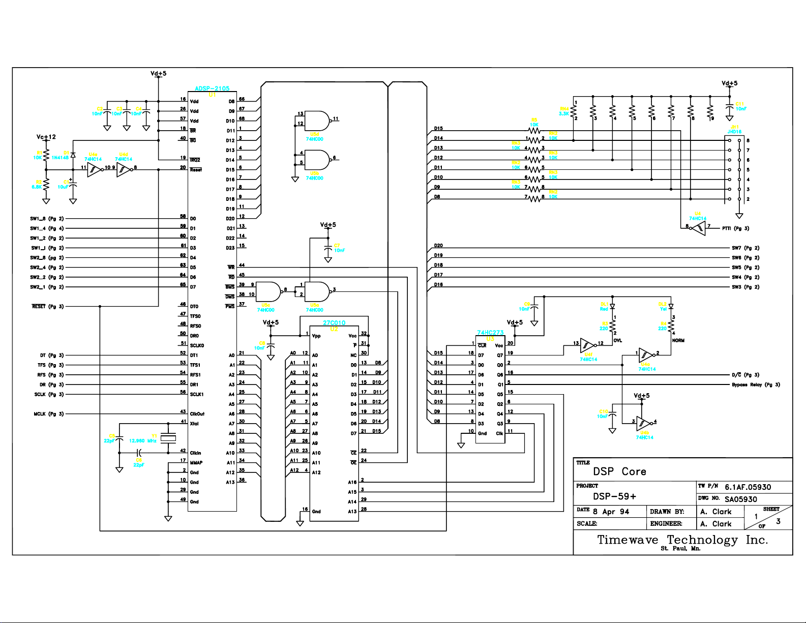
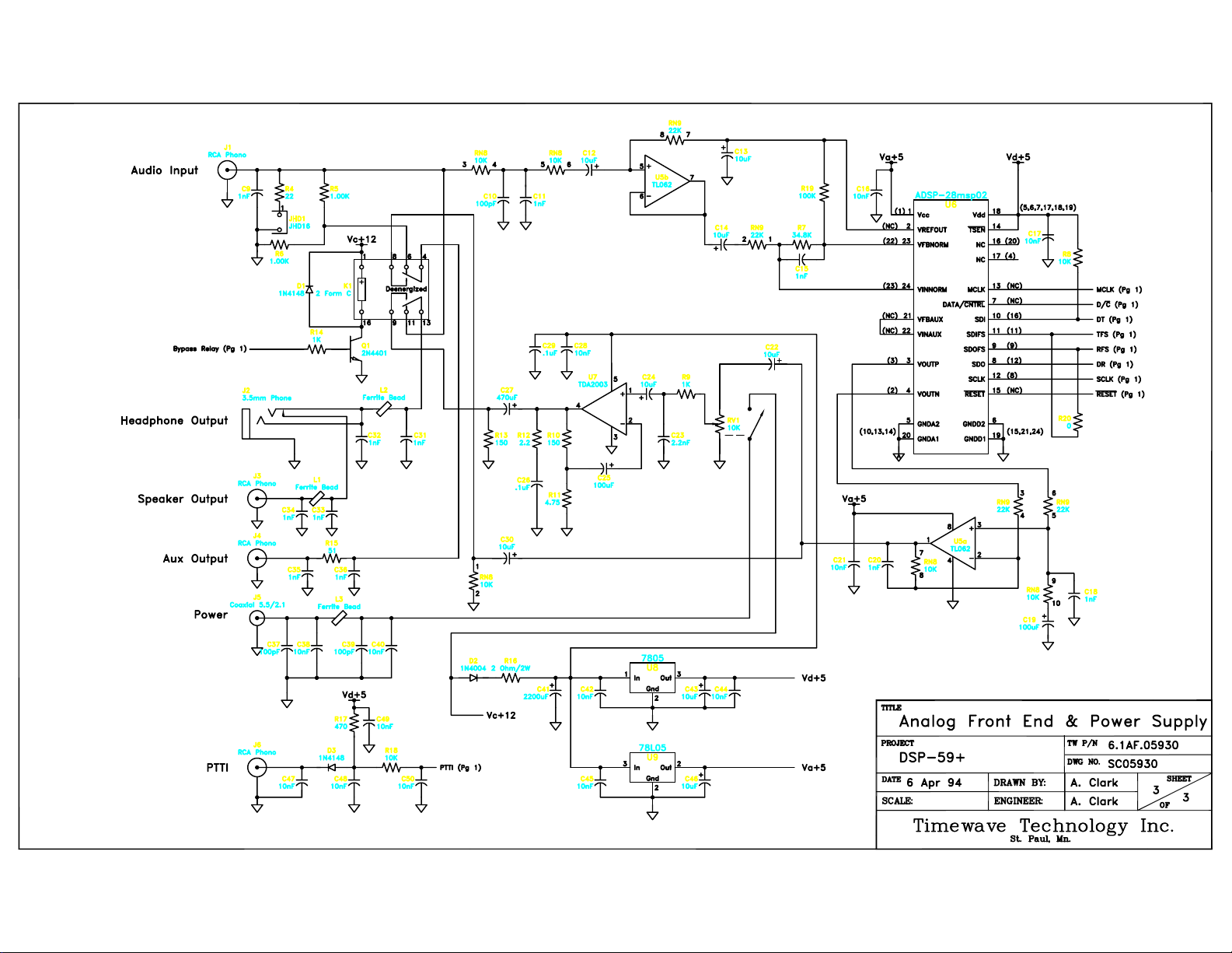
9. Schematic Diagrams
The schematic diagrams in this manual may differ slightly from any particular DSP-59+.
Timewave reserves the right to make changes in the DSP-59+ at any time.
20
Page 22
Page 23

Page 24
Page 25

APPENDIX
Read before attempting to connect your filter.
Wiring information for your Timewave Audio Noise Reduction Filter model DSP-59+
This information is to help you determine which connectors you need for your receiver or transceiver.
Connector requirements vary widely. Check your radio owner’s manual for exact details.
DSP-59+ Inputs and Outputs
The DSP-59+ uses 4 RCA phono jacks on the back of the filter for audio input, audio output, PTTI
switch, and line output. Use cables with RCA phono plugs on one end to connect to the DSP-59+. The
connectors on the other end of the cables are determined by the other devices.
Transceiver Speaker Output
Most receivers and transceivers use a 1/8” mono phone jack for the speaker output. Use a cable with a
1/8” mono phone plug. The other connector is determined by the external speaker input. The most
common external speaker connectors are a RCA phono jack, a 1/8” phone plug, or bare tinned wires.
Multimode Data Converter and Terminal Units (TU)
Data devices use a wide variety of connectors including phone jacks, RCA phono connectors, DIN
connectors, D-subminiature, screw terminals and others. Consult your owner’s manual.
Transceiver PTT and T-R Outputs
Transceiver PTT and T-R outputs use a wide variety of connectors including phone jacks, RCA phono
connectors, DIN connectors, screw terminals and others. Consult your owner’s manual.
Figure 1 shows a RCA phono plug and Figure 2 shows a 1/8” mono plug.
The list of pre-made cables are from the Radio Shack Store.
1. Part #42-2444 - 1/8” phone plug to RCA phono plug (DSP-59+ audio input to transceiver speaker
output).
2. Part #42-2370 - phono plug to split bare tinned wire (DSP-59+ speaker output to external speaker,
or DSP-59+ PTTI from a transceiver PTT output connector).
3. Part #42-2366 is a RCA phono plug to RCA phono plug.
4. Part #42-2459 Add-on volume control for lightweight stereo headset cord with a stereo 1/8” plug.
For more information see your ARRL Handbook on connectors.
Figure 1 Figure 2
24
 Loading...