

Page 1
ANC-4
ANTENNA NOISE CANCELLER
for Reducing
Locally-Generated Noise
Instruction Manual
Revision 2.2a March 17, 2011
Page 2

WARRANTY
TIMEWAVE TECHNOLOGY INC.
LIMITED ONE YEAR WARRANTY
WHO IS COVERED
WHAT WE WILL DO
WHAT YOU MUST DO
WHAT IS NOT
COVERED
SERVICE WARRANTY
HOW TO CONTACT
TIMEWAVE
This warranty is extended only to the original purchaser of the ANC-4.
If your ANC-4 fails in normal use because of a defect in workmanship or materials
within one year of the date of purchase, we will repair or replace (at our option)
the equipment at our factory without charge to you. Timewave will pay for the
return of the warranty-repaired unit to you.
First, double check your connections and operating procedure. If you're certain
that the unit is faulty, notify Timewave Customer Service immediately. If
Timewave is unable to resolve the problem by telephone or email, we will give
you an RMA number and ask you to return the unit. You must pay all shipping
and insurance charges for returning the unit to our factory.
We cannot be responsible for damage caused by accidents, abuse, misuse,
improper installation, or unauthorized attempts to repair the unit.
Timewave service work performed in connection with this warranty is warranted
to be free from defects in materials and workmanship for 30 days from the date
of rerpair. All other terms of the limited warranty apply to the service warranty.
Contact Timewave Customer Service by telephone at (651) 489-5080 or by FAX
at (651) 489-5066.
Mailing and shipping address is 23 Empire Drive
St. Paul, MN 55103-1892
email: [email protected]
TIMEWAVE MAKES NO OTHER WARRANTY, EXPRESSED OR IMPLIED, INCLUDING BUT NOT LIMITED
TO THE IMPLIED WARRANTIES OF MERCHANTABILITY OR FITNESS FOR A PARTICULAR PURPOSE.
web: www.timewave.com
©2002, 2003, 2007 by Timewave Technology Inc., St. Paul,
MN USA
Page 3

CONTENTS
SECTION 1
SECTION 2
SECTION 3
BRIEF DESCRIPTION ............................................................... 1
QUICK OPERATION ................................................................. 3
Connect Power ................................................................................ 3
Connect Noise Antenna .................................................................. 3
Connect Outside Antenna ............................................................... 3
Connect Unit to Receiver Antenna Connector ................................ 3
Connect to Station Ground ............................................................. 3
Turn On Power ............................................................................... 3
Control Settings .............................................................................. 3
Tune in Noise on the Receiver........................................................ 3
Adjusting for Minimum Noise ........................................................ 4
High Frequency Operation (Over 20 MHz) .................................... 5
Reducing Hang Time For Break-In CW Or
AMTOR/PACTOR Use ......................................................... 5
Broadcast Station Notch ..................................................................5
Broadcast Band Filter.......................................................................5
CONNECTIONS .......................................................................... 8
Power Requirements ....................................................................... 8
Vehicular Operation ....................................................................... 8
Main Antenna Input ........................................................................ 8
Radio Input ..................................................................................... 8
Noise Antenna ................................................................................ 8
SECTION 4
SECTION 5
SECTION 6
SECTION 7
SECTION 8
CONTROLS & INDICATORS ................................................... 9
NOISE PHASE Control .................................................................. 9
PHASE RANGE pushbutton .......................................................... 9
FREQ RANGE pushbutton ............................................................. 9
NOISE GAIN Control .................................................................... 9
OPERATION .............................................................................. 10
Local Noise ................................................................................... 10
Active Antenna ............................................................................. 10
General Operating Hints ............................................................... 11
TECHNICAL INFORMATION ............................................... 12
Specifications................................................................................ 12
TROUBLESHOOTING ............................................................. 13
GENERAL THEORY OF OPERATION ................................ 15
Page 4

FIGURES
FIGURE 1
FIGURE 2
FIGURE 3
FIGURE 4
FIGURE 5
FIGURE 6
FIGURE 7
Front Panel Controls ....................................................................... 6
Rear Panel Connectors.................................................................... 6
Connection Diagram ....................................................................... 7
Printed Circuit Board Parts Placement ......................................... 16
Principle of Operation .................................................................. 16
Block Diagram .............................................................................. 17
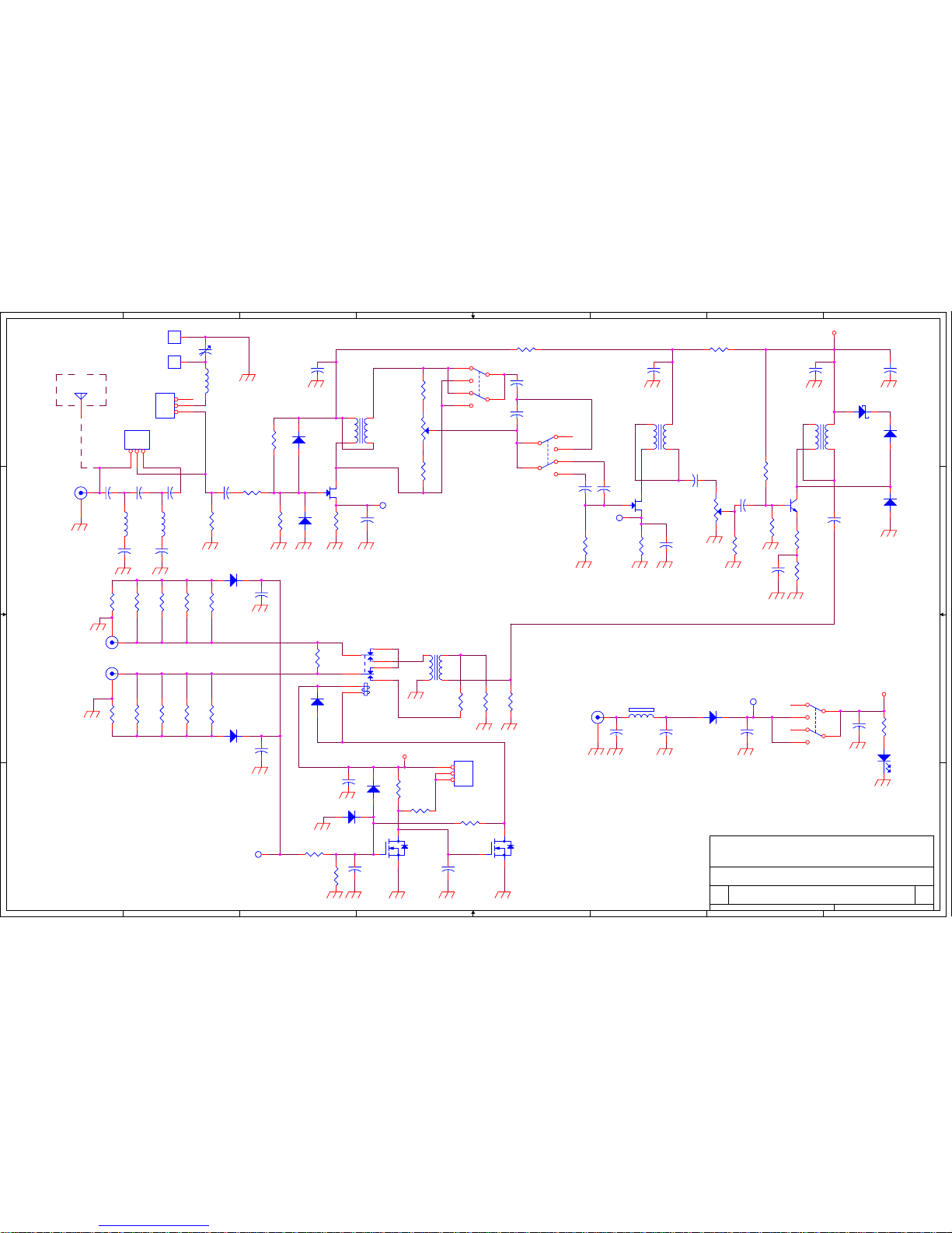
Schematic Diagram ....................................................................... 18
Page 5

SECTION 1
BRIEF
DESCRIPTION
The ANC-4 is an rf device which is designed to provide cancellation of
locally generated noise from signals received by a primary antenna. This
unit is employed right at the antenna connector of the receiver or
transceiver to cancel locally generated noise, such as power line noise,
computer noise, TV-generated interference, etc., before it gets into the
receiver and affects the receiver AGC circuits. This will allow the
reception of signals well below the noise level induced by the local
interference.
To cancel locally generated interference, the interference signal must be
detected and its phase and magnitude adjusted so that it matches the
offending interference, but is 180 degrees out of phase, effectively
cancelling the interference. This scheme is particularly effective at
reducing local power line noise or other locally generated noise types.
This unit may be used with any receiver or transceiver with rf power
output of 250 Watts PEP or less. An rf detector built into the unit
automatically bypasses the network whenever transmit rf is detected.
The unit is NOT designed to be used at the output of a high power linear
power amplifier, but must be installed at the lower rf level of the
transceiver, if transmitting is anticipated. In other words, if you use a
linear amplifier, place the ANC-4 between the transceiver and the linear
amplifier.
Controls are provided on the front panel to allow adjustment of both the
phase and magnitude of the local interference, providing extremely deep
cancellation of the offending interference.
The unit connects between the main station antenna and the receiver
antenna connector. The DC power mating connector for the ANC-4 is
supplied with each unit. UHF (SO-239, which mates with a PL-259 plug)
connectors are used for the outside antenna and the output to the
receiver. A short wire antenna
pickup antenna. This will generally be satisfactory for eliminating
noises generated around the operating position or in the house, but are
generally not large enough to eliminate noises generated outside the
home, such as power line noise. For noises generated outside the home,
we recommend that you mount a small noise dipole (6 feet of wire each
side of center) outside perhaps down in the shrubs or some other area a
foot or two above ground, and broadside to the noise source, such as
parallel to power lines. Feed the noise probe at the center with coaxial
cable, shielded wire or even lampcord and connect it to the NOISE
ANTENNA connector J1, located on the rear of the ANC-4, using an
RCA plug. (Connect the center conductor of shielded wire or one side
of the lampcord to the center pin of the RCA phono plug, and the shield
or other dies of the lampcord to the ground side of the RCA plug.) The
short wire antenna supplied connects to an RCA jack on the rear panel
of the unit. Any noise antenna that works, including combinations of
horizontal and vertically polarized antennas, may be used.
The ANC-4 can be used to cancel ignition noise, alternator whine or
other noise types found in an automobile. To provide sufficient noise
signal to the unit, it may be necessary to run a wire from the NOISE
ANTENNA connector into the engine compartment to act as a noise
pickup. It will probably be necessary to readjust the NOISE PHASE and
NOISE GAIN controls when changing from one band to another, but the
settings should hold over an entire Amateur band.
is supplied with each unit to act as a noise
1
Page 6

The ANC-4 may be used as an active antenna by plugging the noise antenna
(or a longer wire antenna) into the noise antenna jack and using the NOISE
GAIN control to increase the antenna output. See Section 5 ACTIVE
ANTENNA. The unit may also be used as a diversity combiner to null
interfering signals. See Section 5.
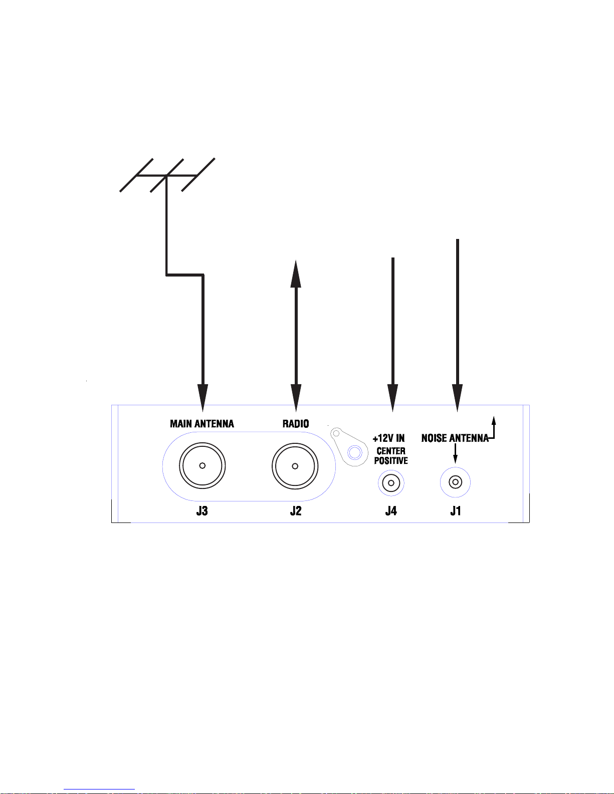
This section lets you get “on the air” with the ANC-4 as quickly and as simply
as possible. Refer to the Connection Diagram Figure 3. See the following
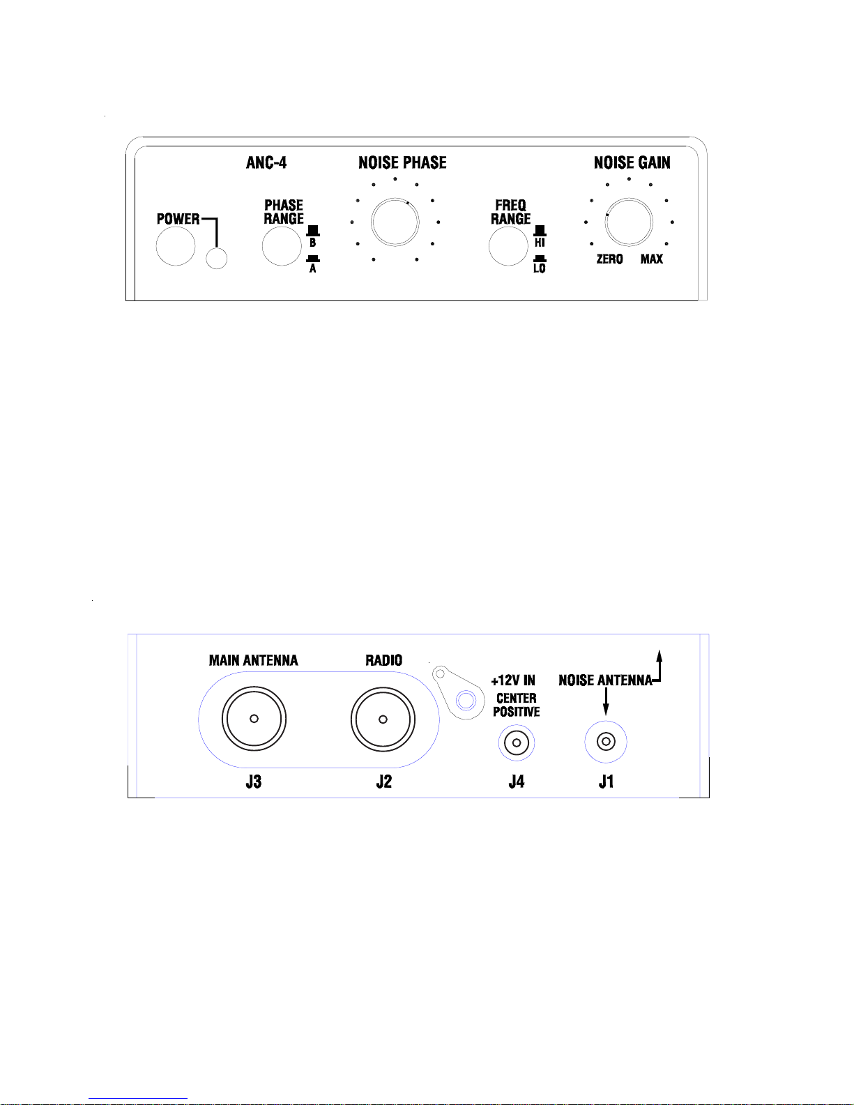
sections of this manual for more detailed information. Refer to Figures 1 and
2
Page 7

SECTION 2
2 for location of front and rear panel connectors and controls.
QUICK
OPERATION
CONNECT POWER
CONNECT NOISE
ANTENNA
The ANC-4 operates from a nominal +12VDC power source. Plug an
AC to 12VDC adapter into the ANC’s DC IN (J4) jack on the rear panel.
The unit is protected for reverse polarity, so no damage will result if the
correct polarity is not observed, but the unit will not operate. If you solder
on your own power plug, be sure to check for the correct polarity - center
terminal is positive - before connecting to the ANC-4. Use the Timewave
AC-1 or similar AC-to-DC adapter with at least 300 mA current
capacity. The power input mating connector is coaxial, 2.1mm ID and
5.0 to 5.5mm OD, center positive. A mating plug is included with the
unit. (Older JPS ANC-4 units use a 2.5 mm ID power connector).
Connect the Noise Antenna, using either the short wire antenna (supplied
with the unit) or your own noise antenna, to the unit. NOTE: The noise
antenna supplied with the unit is likely to be effective only for noise
generated within the operating area or room and will not be
adequate for reducing power line or other noises generated outside
the home. See Section 3 for outside noise antenna suggestions. The
wire antenna comes with an RCA phono plug and plugs into the phono
jack (J1) on the rear of the unit. This jack is also used to connect your
own noise antenna, if desired. The RCA phono connector provided with
the wire antenna may be used to connect your own outside noise antenna
by unsoldering the wire and connecting the coax center conductor to the
center pin of the RCA connector and the coax shield to the outside of the
RCA connector. Use the shortest length for the noise antenna that will
provide a good null with the NOISE GAIN control in its mid range.
CONNECT OUTSIDE
ANTENNA
CONNECT UNIT TO
RECEIVER ANTENNA
CONNECTOR
CONNECT TO
STATION GROUND
TURN ON POWER
CONTROL SETTINGS
Using a UHF connector, connect the outside antenna to the MAIN ANT
connector (J3) on the rear of the unit.
Using a UHF connector and coaxial cable, connect the unit from the
RADIO connector (J2) on the rear of the unit to the receiver or
transceiver rf input or ANTENNA connector.
Connect the rear panel ground connector to your station ground. This
will reduce the effect of hand capacitance on the settings as you null out
the local noise.
Turn on the ANC-4’s POWER switch. The yellow LED next to the
switch should be illuminated.
Set the NOISE PHASE control to the full CCW position. Set the PHASE
RANGE pushbutton in the “IN” (“A”) position. Set the FREQ RANGE
pushbutton in the “IN” (LO) position. Turn the NOISE GAIN control
fully CCW to ZERO.
Tune your receiver to a frequency in the 3 to 4 MHz band (80 Meters).
Find a spot where you hear only the noise level. If the noise is generated
locally, such as close-by power lines, computers, TV, etc., you should be
able to adjust the NOISE PHASE and NOISE GAIN controls to reduce
the noise level considerably. If the noise you receive is not generated
locally, the unit will probably have little effect on your noise level.
TUNE IN NOISE ON
THE RECEIVER
Turn the NOISE GAIN control slowly CW (clockwise) while observing
the receiver “S” meter. Note when the noise level changes, either
3
Page 8

ADJUSTING FOR
MINIMUM NOISE
4
increase or decrease. Now adjust the NOISE PHASE control until you
see the “S” meter dip. If you do not see a dip or rise in the “S” meter
reading, try changing the PHASE RANGE pushbutton to the “OUT”
(“B”) position and readjust the NOISE PHASE control. One position of
the PHASE RANGE pushbutton provides a NOISE PHASE range from
0 to 180 degrees, while the other position provides a NOISE PHASE
range from 180 to 360 degrees. One of the settings of the PHASE
RANGE button will provide the proper phase so that a good null can be
attained. Readjust the NOISE GAIN and NOISE PHASE controls
alternately until the local noise has been cancelled. If you cannot obtain
a null, follow the procedure given in the following paragraphs to
determine if adequate noise is being picked up by the noise antenna. If
you obtain a null of the noise, but it is not as deep as you believe it should
be, try changing the polarity of the noise antenna to agree with the
polarity of your main station antenna. Although the vertical whip may
do a good job of cancelling the noise regardless of the main antenna
polarity, better performance (deeper nulls) can be obtained in some
cases when the main antenna and the noise antenna have the same
polarity. When a null has been reached, you now hear the noise level you
would have if no local noise was present, because you have just
cancelled the locally-generated noise. Now you will hear signals that
you didn’t know were there before. Or you’ll get good copy on signals
that you couldn’t quite hear because they were in the noise level.
If your receiver does not have an “S” meter, listen carefully to the noise
level. When you hear the noise level increase with noise from the noise
antenna, switch to the NOISE PHASE control and listen for the null in
the noise. Switch between the NOISE PHASE and NOISE GAIN
controls to attain the local noise null. The null obtained is normally good
for most of, if not the entire band in which you’re listening. If you go to
a new frequency, you will probably have to readjust the settings on the
NOISE PHASE and NOISE GAIN controls to recancel the local noise.
If you cannot obtain a satisfactory null in the noise, make the following
check to determine if adequate noise is being picked up by the noise
antenna.
(1) Turn both NOISE PHASE and NOISE GAIN controls fully CCW.
(2) Note the S meter reading on noise received from the main antenna.
Also listen to the character of the noise.
(3) Disconnect the main antenna and increase the NOISE GAIN in a CW
direction until the S meter reads the same as it did with noise from the
main antenna. Listen to the noise to be sure it sounds the same as it did
in step 2 above. If you cannot get the S meter reading high enough to
equal the reading taken in step 2, the noise antenna length must be
increased to pick up enough noise to properly cancel that received by the
main antenna.
(4) If the character of the noise is not the same in step 3 as it was in step
4, you may need to place an outside noise dipole to pick up the noise.
Feed the output from this outside probe through shielded wire or coaxial
cable to the NOISE ANT connector on the rear of the ANC-4.
For operation at frequencies above 20 MHz, the FREQ RANGE
pushbutton should be in the “OUT” ( HI) position. This centers the
network so that it will operate properly at these higher frequencies. If you
have trouble getting a good null at high frequencies, try placing the
FREQ RANGE switch in the LO position and readjust the NOISE
PHASE and NOISE GAIN controls. All other adjustments should be
made as noted above to cancel the local noise. The unit will cancel local
noise down to about 100 KHz and up to about 80 MHz.
Page 9

HIGH FREQ
OPERATION
(Over 20 MHz)
REDUCING HANG
TIME FOR BREAK-IN
CW OR AMTOR/
PACTOR USE
BROADCAST
STATION NOTCH
BROADCAST BAND
FILTER
To reduce the Time to Return to Receive Mode When RF is Not Present,
parallel resistor R29 with 22k, 1/4W. This can easily be done internally by
changing jumper J1 (DELAY) from position 1-2 (NORMAL), to position 23 (FAST). This will decrease the relay hang time from 500 msec to
approximately 7 msec.
If a local broadcast station overloads the NOISE ANTENNA amplifiers, it can
be sharply attenuated with a tunable trap, C27 and L2. To activate the trap,
connect the jumper JP2 to position 1-2. By adjusting the variable capacitor,
station frequencies in the 1000 to 1600 kHz range can be trapped. To trap a
station with a frequency between 800 kHz and 1000 kHz, install a 22 pF
capacitor between E1 and E2 on the printed circuit board. If the offending
station has a frequency below 800 kHz, install a 47 pF capacitor between E1
and E2. To deactivate the tunable trap, place the jumper JP2 in position 2-3.
To attenuate signals from local broadcast stations that are picked up by the
external noise antenna, place Jumper JP3 for the BCB Filter in position 1-2.
This places a high pass filter with at least 50 dB attenuation in the stop band
in series with the noise antenna. If one particular station is so strong that it still
comes in despite the high pass filter, use the BCB TRAP to notch it out. See
paragraph above. To deactivate the BCB Filter, place jumper JP3 in position
2-3.
This section gives detailed information on the connections to the ANC-
4. The unit is quite simple to connect and use, but for best results, follow the
guidelines in this manual. See Figure 2 for Rear Panel Connections.
The ANC-4 operates from +11VDC to +16VDC and requires about 300 mA.
5
Page 10
TIMEWAV E
Figure 1
Front Panel Controls
6
Figure 2
Rear Panel Controls
Page 11
OUTSIDE
MAIN
ANTENNA
TO
RADIO
ANTENNA
INPUT
+12VDC
FROM
POWER
SUPPLY
NOISE
ANTENNA
Figure 3
Connection Diagram
7
Page 12

SECTION 3
Power can be supplied from any filtered DC source. An AC to 12VDC
adapter is available from JPS Communications at slight additional cost.
CONNECTIONS
POWER
REQUIREMENTS
VEHICULAR
OPERATION
MAIN ANTENNA
INPUT
RADIO INPUT
NOISE ANTENNA
The ANC-4 may be operated directly from the power system of any
12VDC negative ground vehicle.
The MAIN ANT input (J3) connector is a UHF (SO-239) type for use
with coaxial rf cables, such as RG-8 or RG-58. This connector serves as
the rf input from the outside or station antenna system.
The RADIO (J2) connector is also a UHF (SO-239) type for use with
coaxial rf cables, such as RG-8 or RG-58. This connector provides the
output from the antenna to the receiver. When the ANC-4 power is off,
the MAIN ANT is bypassed directly to the RADIO connector.
The NOISE ANTENNA connector on the rear panel (J1) is an RCA
phono jack for connecting the short wire noise antenna or your own noise
antenna to the ANC-4. This antenna picks up locally generated noise to
the exclusion of desired long distance signals, and is used as a reference
signal which can be varied in magnitude and phase for cancellation of the
local noise. Keep in mind when selecting which noise antenna to use that
you may get deeper noise nulls by having the same polarization on both
the noise antenna and the main antenna. In either case, the noise antenna
should be kept as short as possible to provide a good noise null with the
NOISE GAIN control in its mid range.
If sufficient noise cannot be picked up by the noise antenna supplied
with the unit, it may be necessary to install a noise dipole or noise
probe outside to more clearly pick up the noise. A noise dipole of 3
to 6 feet either side of center, fed with shielded wire or coaxial cable, will
generally suffice. The dipole should be turned broadside (parallel) to the
noise source and should be located 2 to 4 feet above ground, perhaps in
shrubs around the house, but where it can "see" the power lines or other
noise source. This will prevent it from receiving much if any of the
desired signal. After installation, perform the test in the SECTION 2,
ADJUSTING FOR MINIMUM NOISE to be sure that adequate noise
pickup is available from the noise antenna. It is most desirable to have
the matching noise level occur when the NOISE GAIN control is
somewhere in its middle range. Otherwise, the null may be obscured if
it occurs too close to either end of the control.
8
Page 13

SECTION 4
CONTROLS &
INDICATORS
This section explains the operation of the ANC-4 controls. See Figure 1
for the location of Front Panel Controls.
NOISE PHASE
CONTROL
PHASE RANGE
PUSHBUTTON
FREQ RANGE
PUSHBUTTON
NOISE GAIN
The NOISE PHASE control adjusts the phase angle of the signal from the
noise antenna to 180 degrees for maximum cancellation of the local noise.
The PHASE RANGE pushbutton provides two different networks to
allow greater range of adjustment of the NOISE PHASE control to achieve
the deepest null of local noise interference. When the button is pushed in,
the phase network is in the “A” position, which is used for most situations.
When the button is out, the phase network is in the “B” position. No
position on this switch is more “right” than the other. The proper or “right”
position is that which gives the best null. The FREQ RANGE button can
be used in conjunction with this pushbutton to give even greater phase
nulling range at low frequencies by placing it in the HI position.
The FREQ RANGE pushbutton extends the frequency range over which
the NOISE PHASE and NOISE GAIN controls are effective. In the “IN”
position (LO), the network is set for frequencies below 20 MHz. In the
“OUT” position (HI), the network is set for frequencies above 20 MHz.
Note that the HI position is also usable for low frequencies and may be
required if a satisfactory phase null cannot be obtained with the switch in
the LO position.
The NOISE GAIN control adjusts the level of the signal picked up by the
noise antenna so that the magnitude of the offending interference can be
cancelled. When the ANC-4 is used as an active antenna, this control
adjusts the gain of the antenna.
9
Page 14

SECTION 5
OPERATION
LOCAL NOISE
This section describes the operating procedure for best results with the
ANC-4.
When the unit is connected as shown in Figure 3, locally generated noise
can be cancelled, in many cases completely. The controls and switches
should be manipulated as follows: (Refer to Figure 1).
1. Use your receiver “S” meter as a noise level indicator.
2. Set the NOISE PHASE control initially fully CCW and turn the NOISE
GAIN control fully CCW. Set the PHASE RANGE pushbutton “IN” to
the A position, and the FREQ RANGE pushbutton “IN” to the LO
position for frequencies below 20 MHz, or release it to the “OUT” or
HIGH position for frequencies above 20 MHz. (See "adjusting for
Minimum Noise" in Section 3 for further discussion.)
3. Slowly increase the NOISE GAIN control clockwise until a change,
increase or decrease, in the “S” meter reading is just noted.
4. Now adjust the NOISE PHASE control until a null is noted on the “S”
meter.
ACTIVE ANTENNA
10
5. Alternately adjust the NOISE GAIN and NOISE PHASE controls until
the best null is obtained. If interaction due to hand capacitance is noted,
ground the case of the ANC-4 to your system ground.
6. If a good null cannot be obtained with the PHASE RANGE pushbutton
in the A (in) position, release the pushbutton to the B position and
readjust. A null should be obtained in one of the two PHASE RANGE
switch positions. Remember that the “right” switch position is that which
gives the best null.
7. For the deepest noise nulls, it may be necessary to change the noise
antenna polarity (horizontal or vertical) to be the same as that of the main
antenna.
8. When changing bands, it will probably be necessary to readjust the
network to reduce the noise on the new band. Normally, the adjustment
will hold over a frequency range of several kilohertz without requiring
readjustment. So if you adjust the noise cancellation in any one ham band,
it will generally hold throughout that band. However, different noise
sources may be present in different parts of the same band, so that some
readjustment may be required if this occurs.
9. If a null cannot be obtained using the noise antenna supplied with the
unit, you may have to install an external noise antenna. SECTION 2,
ADJUSTING FOR MINIMUM NOISE provides a test which will
determine if adequate noise is being provided by the noise antenna.
SECTION 3, NOISE ANTENNA gives some hints for an external noise
antenna and where it should be physically located.
The ANC-4 can be used as an active antenna. The NOISE GAIN control can then
be used to provide amplification of the signals received by the antenna.
Page 15

For active antenna use, do not connect an antenna to the MAIN ANTENNA
connector.
Use a wire antenna can be connected to the rear panel NOISE
ANTENNA connector, J1. Best results will be obtained by using the longest practical
length of wire for this antenna.
GENERAL
OPERATING HINTS
When used as an active antenna, set the NOISE PHASE control fully clockwise for
best results. Set the FREQ RANGE pushbutton to agree with the frequency band in
which you are operating. The position of the PHASE RANGE pushbutton is not
important.
Following are some helpful hints for operating with the ANC-4:
To prevent damage to the ANC-4 when an antenna tuner is used,
simply turn off the power on the ANC-4 until the tuning process
is complete.
If the PHASE GAIN control is too close to either the CCW or CW
end,merely adjust the noise antenna length to center the control. In
other words, keep the noise antenna length to the minimum required
to get a good null while keeping the NOISE GAIN control in its mid
range.
If you use an antenna tuner, wait until the antenna has been properly matched
before adjusting the ANC-4 for local noise null.
If the local noise is not stronger in the noise antenna than it is in the main antenna,
adjusting for a null will likely reduce the desired signal as well. It is desirable
to have the noise antenna as close to the noise source as possible for best
performance, so an external noise antenna may be required.
DO NOT connect the noise antenna to a high gain outside antenna unless a series
attenuator is used. Unless the signal is attenuated, the received signals will
overload the internal amplifier and will cause intermodulation distortion. The
loss in signal strength through the attenuator can be made up by adjusting the
NOISE GAIN control.
You will likely find that the ANC-4 will make operation of a DSP noise reducer,
such as the Timewave DSP-599zx., much more effective because the ANC-4
will eliminate noise before it gets into the receiver and affects the receiver AGC
circuits.
If you are situated close to an AM broadcast station, you may need to trap the BC
signal to prevent overload of the noise amplifier in the ANC-4. A tunable trap
is included on the pc board to eliminate BC station interference. See Section 2,
BROADCAST BAND NOTCH for further information. If more than one station
is involved, merely place jumper JP3 in position 1-2. This engages a highpass
filter which attenuates the broadcast band by at least 50 dB.
NOTE: If the NOISE GAIN is set too high, the ANC-4 will introduce noise
instead of removing it. Noise cancellation is dependent upon a good balance
between the NOISE PHASE and NOISE GAIN controls.
If two antennas are available and located with space diversity, you can use the
ANC-4 to null interfering stations as shown in figure below.
In order to obtain the best noise null, it may be necessary to change the noise
antenna polarization (horizontal or vertical) to be the same as that of the main
station antenna.
11
Page 16

SECTION 6
TECHNICAL
INFORMATION
SPECIFICATIONS
Operating Frequency Range 500 kHz to 80 MHz
(usable down to 100 kHz)
Signal Loss, Main Ant. to Radio 6 dB
Rf Input Level, Main Antenna 3 Vrms maximum
Maximum Transmit Rf Power 250 W PEP or Average
Through Unit
Time to Switch to Bypass When 7 mSec, typical
Transmit Rf is Detected
Time to Return to Receive Mode Approx. 500 msec or 7 msec, typical
When Rf is Not Present intenally selectable, (hang time)
Typical Local Noise Types Power Line Noise, Computer Noise,
TV Noise, etc.
Noise Cancellation Typically 40 dB or greater
Front Panel POWER switch, POWER LED,
PHASE RANGE switch, NOISE
PHASE control, FREQ RANGE
switch, NOISE GAIN control.
12
Rear Panel Power Input, Noise Antenna Input,
Main Antenna Input, Radio Output
Input Power +11 VDC to +16 VDC @ 150 mA,
reverse polarity protected
Size 1.7"H x 6"W x 4.3"D
(4.3cm x 15.2cm x 10.9cm)
Weight 2 pounds (.91 kG)
Temperature Ranges Operating: -20oC to +55oC
Storage: -40oC to +85oC
Humidity Up to 95% @ +55oC
Page 17

SECTION 7
TROUBLE-
SHOOTING
Symptom Possible Fault
POWER ON LED Check AC power source, polarity and power line connections.
does not light. Check for proper seating of plug in DC power jack
Unit comes on, but Check all antenna connections on rear panel. Make sure
no signals heard cables go to correct connectors in Receiver
Noise received cannot Received noise may not be locally generated. Follow nulling
be nulled instructions carefully. Make sure you try both settings of PHASE
RANGE switch and the FREQ RANGE switch when nulling if
difficulty is noted. If frequency is above 20 MHz, set the FREQ
RANGE switch to the HI position. NOISE GAIN control may be set
too high initially. The noise antenna length may be too great,
particularly if the noise is severe. Shorten the noise antenna length
until a satisfactory null can be obtained with the NOISE GAIN
control in its mid range. Change the noise antenna
polarization (horizontal or vertical) to agree with that of the main
station antenna. If you can approximate the location of the noise
source, place a short external noise antenna as close to the source
as you can, or use a short dipole facing toward the noise source as
a noise antenna. NOTE: The short wire noise
antennas supplied with the unit are not adequate to cancel
local power line noise or other noise generated outside the
home. You will need to install an outside antenna. See
Section 3, NOISE ANTENNA for suggestions on antenna size
and location. If problem persists, contact Timewave Customer
Service Department.
Noise received cannot
be nulled.
Noise received on noise antenna is too low. Noise received on noise
antenna is different from that received by main antenna. To determine
if this is the case, perform the following procedure:
(1) Connect up the unit as described in the manual. Turn the unit
power on.
(2) Turn both the NOISE PHASE and NOISE GAIN controls fully
CCW.
(3) Now with the main antenna connected, note the S meter reading
and listen to the character of the noise (is it a "buzz" or a "crackle",
etc.?)
(4) Disconnect the main antenna from the ANC-4.
(5) Turn the NOISE GAIN control CW until it is somewhere in its
mid-range and observe the S meter reading. Is it as high as the
reading obtained in step 3? Is the character of the noise the same as
that heard in step 3? If the answer to both questions is "YES", you
13
Page 18

should be able to arrive at a satisfactory null of the noise. (Hint: When you
reach the same S meter reading as before, leave the GAIN where it is,
reconnect the main antenna and try to null with just the NOISE PHASE
control. You may have to alternate between PHASE and GAIN a few times
to get the deepest null.) If the answer to either question is "NO", then a null
probably cannot be achieved.
(6) If the noise sounds the same in steps 3 and 5, but you can't get a high
enough S meter reading from the noise antenna alone, you need a longer
noise antenna or need to locate the noise antenna closer to the noise source.
(7) If you can get a similar S meter reading, but the noise sounds different in
step 5 from what it sounds like in step 3, your noise antenna is picking up
noise that is not being heard by the main antenna and the noise antenna must
be relocated so that it DOES pick up the noise appearing on the main antenna.
(For instance, your outside antenna may be receiving noise from power lines,
while the indoor noise antenna may be picking up noise from a nearby
computer, noise which is not heard by your main antenna). In most cases, a
simple short dipole can be placed outside in shrubs or some other low area,
but in view of the noise source, if possible. The noise antenna is then fed to
the ANC-4 NOISE ANTENNA jack (rear of the unit) with shielded wire.
Repeating the above tests will let you determine if you will be able to null the
main antenna noise or not. Some adjustment of noise antenna length or
position may improve the null.
14
Page 19

SECTION 8
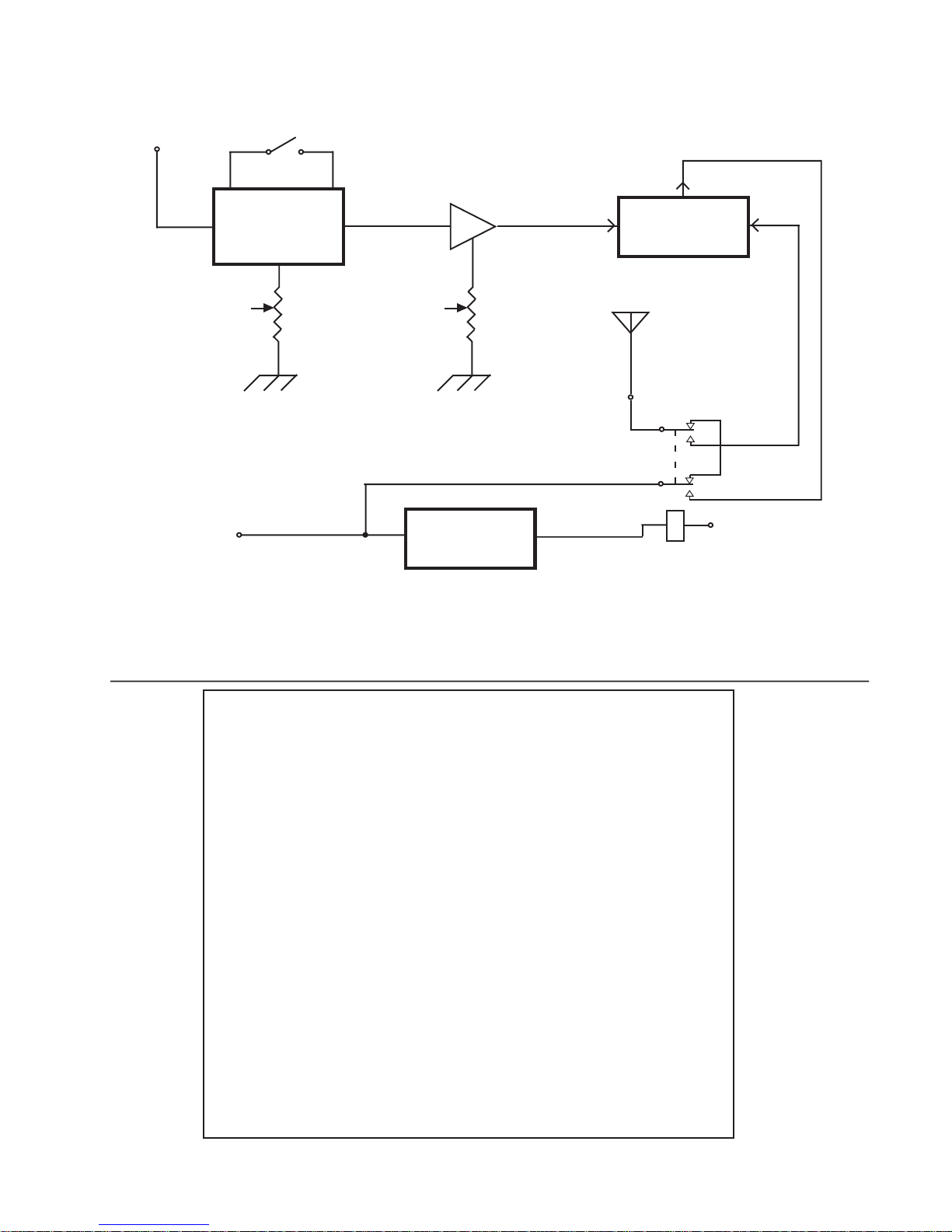
Figure 6 is a block diagram of the ANC-4 showing the elements that are used to cancel
locally generated noise from the signal received by the station main antenna system.
GENERAL
THEORY OF
OPERATION
(See Figure 5)
The station antenna picks up noise, both locally and remotely generated, as well as desired
signals and passes everything directly to the receiver. If the noise level is strong enough,
it will take over the receiver AGC system and reduce the receiver gain for weaker desired
signals, masking them. The detected audio output then contains mostly noise information
unless the desired signal is of sufficient strength to overcome the noise signal amplitude.
This reduces the number of signals actually heard by the operator to those stronger than
the received noise level. When the noise level from local sources, such as power lines,
computers, etc., is strong enough to give high “S” meter readings on the receiver, the
number of intelligible signals received by the operator is greatly reduced when compared
to what could be heard if the local noise level could be overcome. Now DSP noise
reduction devices can allow the operator to improve the intelligibility of signals close to
or in the noise level, but cannot “dig out” those signals which have been masked by the
local noise. The ANC-4 provides a means to allow the operator to cancel the local noise
and let him hear those signals previously masked by that noise.
The signal from the MAIN antenna is combined in a special network with a signal from
the NOISE antenna. The MAIN antenna signal contains desired information as well as
noise. The NOISE antenna signal, which contains mostly the local noise, is amplified and
passed through a phase shift network so that its phase can be adjusted to 180 degrees
compared to the MAIN antenna signal. Front panel controls, NOISE PHASE and NOISE
GAIN, let the operator adjust the NOISE antenna phase and gain to just equal the noise
signal magnitude picked up by the MAIN antenna, but shifted 180 degrees in phase. Two
phase shift networks (PHASE) are incorporated to give maximum flexibility and cover
most local noise situations. A switch (FREQ RANGE) is also provided to tailor the noise
cancellation network for operation at frequencies above 20 MHz. The HI range on this
switch is also usable at lo frequencies and provides an additional phase shift network
which may be required if a satisfactory phase null cannot be obtained with either PHASE
switch position. The combined signals, with the local noise cancelled, are passed on to
the receiver via the RADIO connector on the rear panel. The networks in the ANC-4 allow
cancellation of local noise up to an operating frequency of about 80 MHz or so.
Desired Signal + Atmospheric Noise + Local Noise - Local Noise =
Desired Signal + Atmospheric Noise
When properly adjusted, 50 dB reduction of the locally generated noise is possible,
leaving only the normal atmospheric noise level existing on the band. (Observing the “S”
meter readings before and after local noise cancellation will make this apparent.) Signals
that were masked by the local noise can now be heard. Now that the local noise has been
removed from the received signal, a DSP noise reducer is much more effective when
operating at the audio end of things. Just by eliminating or reducing noise, listening
fatigue can be greatly reduced.
15
Page 20
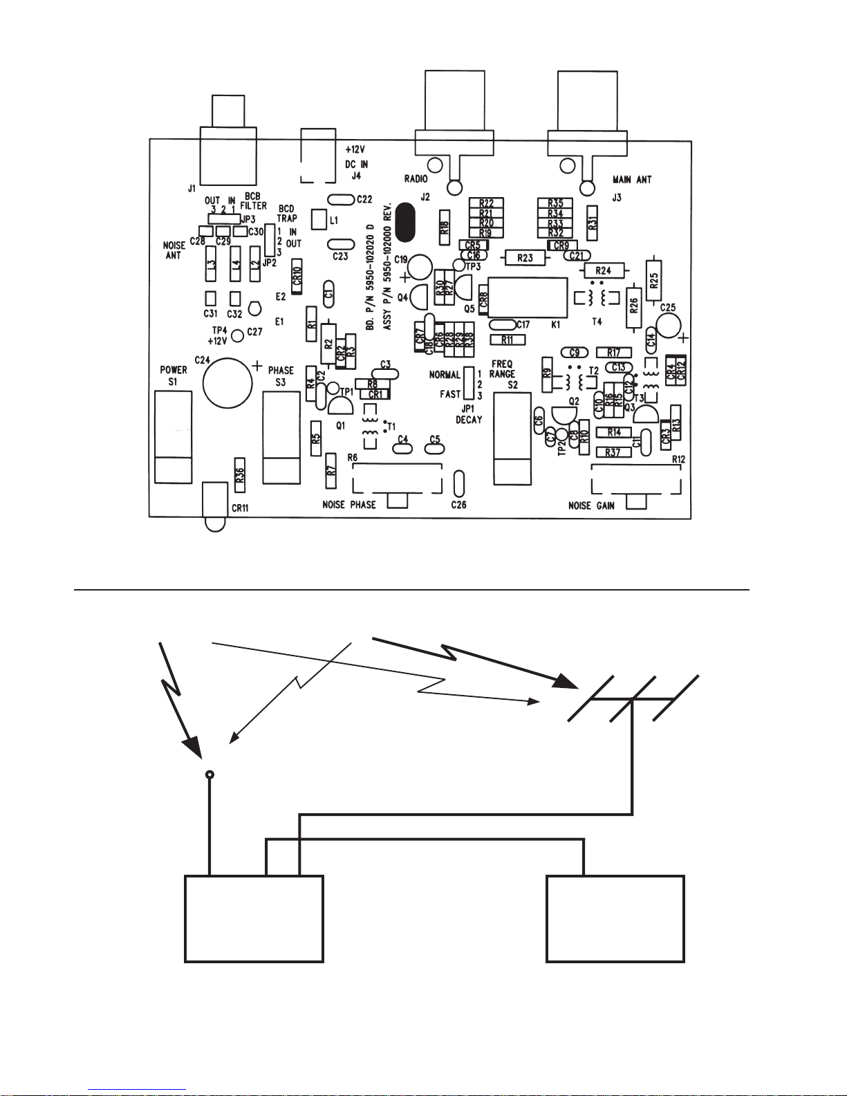
Figure 4
Printed Circuit Board Parts Placement
LOCAL NOISE
Strong
16
Weaker
Noise
Ant
J1 J2 J3
ANC-4
Figure 5
Principle of Operation
DESIRED SIGNAL
Strong
Weaker
Main
Ant
RADIO
Page 21
NOISE
ANTENNA
J1
S2
Phase A/B
Phase
Shift
Network
NOISE
AMP
Hybrid
Combiner
To Radio
R6
NOISE
PHASE
R12
NOISE
GAIN
MAIN
ANTENNA
(or Linear Amp)
J3
J2
RF
K1
Detector
Note:
Relay shown in
transmit/power off
Figure 6
position
Block Diagram
For those who have access to the Internet, Timewave may be contacted at
+12
Timewave also has a Home Page on the World Wide Web
Here you may register a product, view a specification sheet and photo,
request the latest product catalog, view product FAQs, and
read about product upgrades when available.
Feel free to email us if you have technical questions
or comments about your Timewave product.
Email: [email protected]
http://www.timewave.com
17
Page 22
8
8
7
7
6
6
5
5
4
4
3
3
2
2
1
1
D D
C C
B B
A A
+12V
+12V
+12V
Title
Size Document Number Re v
Date: Sheet
of
A.05300
ANC-4 Antenna Noise Canceller
Timewave Technology Inc.
St. Paul, MN 55117
B
11Wednesday, March 12, 2003
FREQ
HI
LO
A
B
ANT
RADIO
MAIN
DC IN
+12V
+
POWER
+
SOURCE
PHASE
YELLOW
GAIN
RANGE
HI
LO
NOISE
PHASE
USE JP1 TO ADJUST DEC AY TIME AFTER KEY-UP:
JUMPER PINS 1 & 2 FOR NORMAL DECAY
JUMPER PINS 2 & 3 FOR FAST DECAY
USE JP2 FOR BC BAND TRAP
JUMP 1 & 2 TOGETHER FOR BC BAND TRAP
JUPM 2 & 3 TOGETHER TO DISABLE TRAP
USE JP3 FOR BCB FILTER
JUMP 1 & 2 TOGETHER FOR BC BAND FILTER
JUMP 2 & 3 TOGETHER TO DISABLE FILTER
1W
NOISE
NOISE
ANT
1W 1W 1W
R29
1M
C2
.1u
L3
47uH
CR5
1N5711
R38
22k
C30
150pF
T1
C29
100pF
C28
120pF
R15
22
Q3
4124
R14
2.2K
+
C25
100uF
C32
270pF
C11
.1u
C31
560pF
R13
4.7K
R31
3K
R6
500
1 3
2
NOISE ANT
J3
E1
1
JP3
BCB
FILTER
OUT IN
123
R183KR19
47K
C26
.1u
R20
47K
R21
47K
R22
47K
T3
K1
DS2Y-DPDT
4
6
8
13
11
9
1
16
CR3
4148
CR4
4148
C14
.1u
CR9
1N5711
C21
1n
R17
10
L2
820uH
T2
R12
500
1 3
2
L1
BEAD
Q2
J310
R10
51
R37
1K
R9
1K
C8
.1u
C7
47p
C6
.1u
E2
1
TP4
R23
51
R24
51
CR12
1N5231B
S2
T4
JP2
BCB
TRAP
OUT
IN
1
2
3
R26
51
C4
100p
R11
10
C27
5-25pF
C5
10p
S3
R25
51
L4
47uH
R7
39
R5
39
TP2
J2
CR7
4148
C17
.1u
S1
SW DPDT
CR6
4148
J4
R27
10K
C22
10n
R28
100K
C23
10n
C18
1n
Q4
2N7000
CR10
4004
C24
1000u
CR11
POWER
R36
1K
R30
10M
Q5
2N7000
TP1
C19
2.2u
C16
1n
C10
.1u
JP1
DECAY
FAST
NORM
1
2
3
R16
100
C12
.1u
C13
.1u
C9
.1u
J1
C3
.1u
R1
100K
C1
1n
CR8
4148
R2
100 1W
Q1
J310
R32
47K
TP3
R33
47K
R4
300
R34
47K
R3
270K
CR2
4148
R35
47K
CR1
4148
R8
1M
 Loading...