

Page 1

Operators & Installation
Manual
Page 2
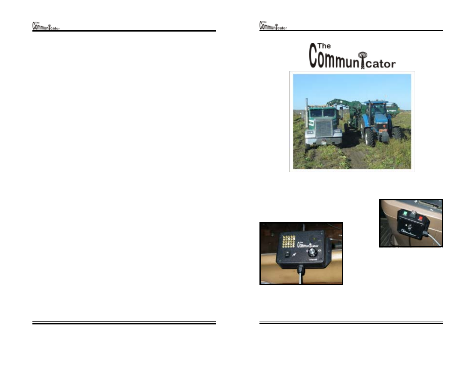
Model 201 Version 1.0
Disclaimer
LIMITED WARRANTY LIMITED WARRANTY
LIMITED WARRANTY
LIMITED WARRANTY LIMITED WARRANTY
This product is warranted against defects for one (1) yearThis product is warranted against defects for one (1) year
This product is warranted against defects for one (1) year
This product is warranted against defects for one (1) yearThis product is warranted against defects for one (1) year
from date of purchase. Within this period TIME TRONICS INC.from date of purchase. Within this period TIME TRONICS INC.
from date of purchase. Within this period TIME TRONICS INC.
from date of purchase. Within this period TIME TRONICS INC.from date of purchase. Within this period TIME TRONICS INC.
will repair or replace the product without charge, providedwill repair or replace the product without charge, provided
will repair or replace the product without charge, provided
will repair or replace the product without charge, providedwill repair or replace the product without charge, provided
the product is returned to TIME TRONICS INC. prepaid.the product is returned to TIME TRONICS INC. prepaid.
the product is returned to TIME TRONICS INC. prepaid.
the product is returned to TIME TRONICS INC. prepaid.the product is returned to TIME TRONICS INC. prepaid.
Warranty does not cover freight or transportation charges,Warranty does not cover freight or transportation charges,
Warranty does not cover freight or transportation charges,
Warranty does not cover freight or transportation charges,Warranty does not cover freight or transportation charges,
nor does it cover misuse or damage to the product. Except asnor does it cover misuse or damage to the product. Except as
nor does it cover misuse or damage to the product. Except as
nor does it cover misuse or damage to the product. Except asnor does it cover misuse or damage to the product. Except as
provided herein, TIME TRONICS INC. makes no warranties,provided herein, TIME TRONICS INC. makes no warranties,
provided herein, TIME TRONICS INC. makes no warranties,
provided herein, TIME TRONICS INC. makes no warranties,provided herein, TIME TRONICS INC. makes no warranties,
express or implied, including warranties of merchantabilityexpress or implied, including warranties of merchantability
express or implied, including warranties of merchantability
express or implied, including warranties of merchantabilityexpress or implied, including warranties of merchantability
and fitness for a particular purpose. We reserve the right toand fitness for a particular purpose. We reserve the right to
and fitness for a particular purpose. We reserve the right to
and fitness for a particular purpose. We reserve the right toand fitness for a particular purpose. We reserve the right to
make improvements, and additions in the design of the productmake improvements, and additions in the design of the product
make improvements, and additions in the design of the product
make improvements, and additions in the design of the productmake improvements, and additions in the design of the product
without notification.without notification.
without notification.
without notification.without notification.
Model 201 Version 1.0
Installation
Manual
COPYRIGHT 2005COPYRIGHT 2005
COPYRIGHT 2005
COPYRIGHT 2005COPYRIGHT 2005
Page 3
Operators
Manual
The Communicator is a wireless communicating device that makes it easy to direct
truck or tractor drivers into position for efficient non-spill loading on the go.
Placed in the harvester cab, beside your other
controls, the transmitter works off a small finger
operated joystick, which the harvester operator
uses to guide
the driver.
Activating
the joystick
sends a signal to the receiver which then
turns on LED's indicating directional
arrows corresponding to the joystick
direction. In addition to the directional
arrows, there's also a stop and go function.
All the signals are accompanied by a unique beep sequence for audio alertness.
After mounting the transmitter it can be programmed so that the joystick's forward
activation is correct for direction of travel.
Installation
Manual
Page 4
Operators
Manual
Page 3
Model 201 Version 1.0
Model 201 Version 1.0
Mounting the Transmitter
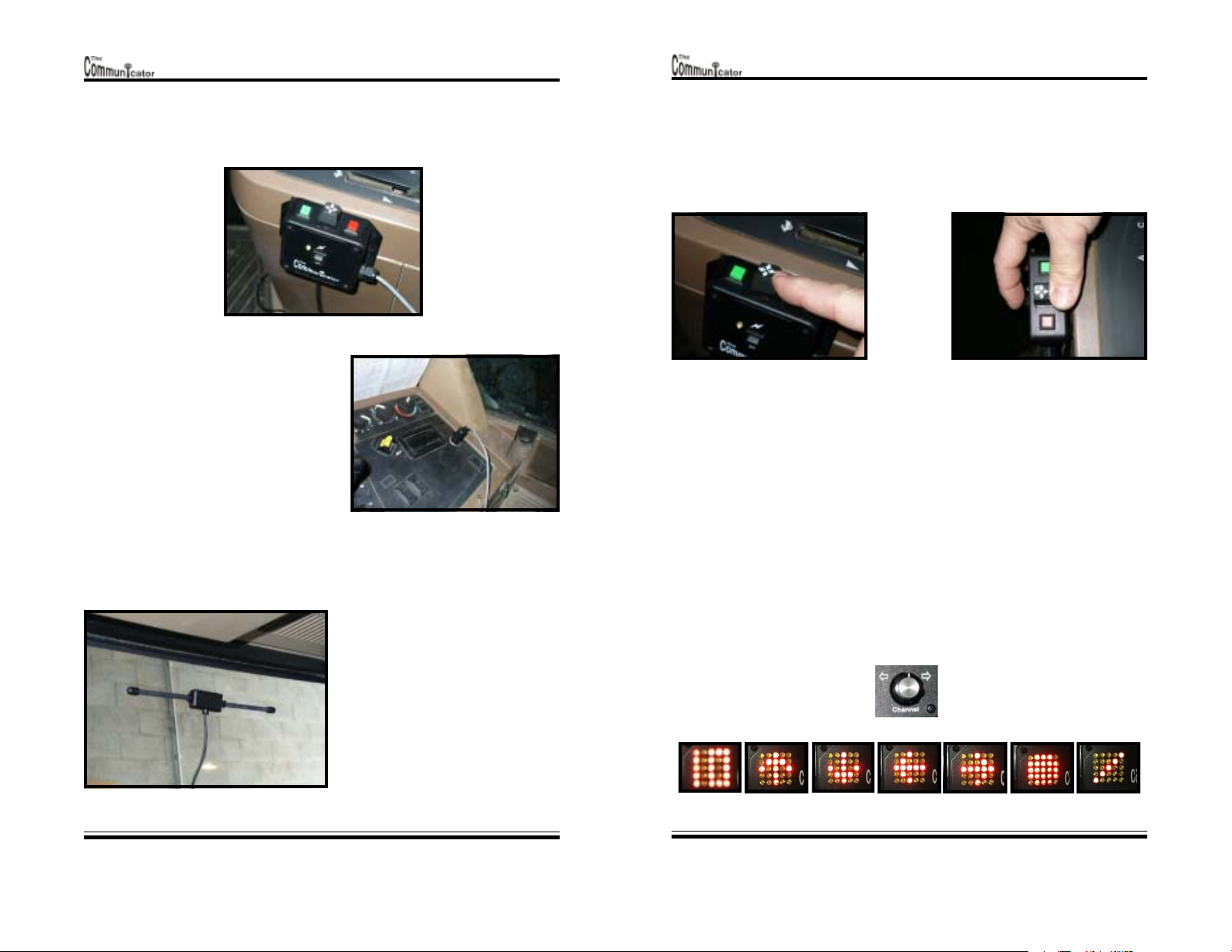
Mount the transmitter at a convenient
location so as to give the operator easy
access to the joystick and switches. Plug the
power cable into a 12vdc lighter adapter. If
no lighter adapter is available cut the
adapter off and connect directly to a 12vdc
power source. The RED wire is positive(+)
and the BLACK wire is ground(-).
Mounting the Antenna
Programming the Mounting
Direction
To program the mounting direction, press and hold the JOYSTICK in the forward
direction of travel while turning on the power switch. Hold the JOYSTICK until
the LED changes the blink sequence. (Approximately 3 seconds). The transmitter
will automatically store this direction as the forward position. All other joystick
directions will be adjusted automatically.
Turn the power off and then on again without pressing any buttons for normal
operation.
Installation
Manual
Page 5
Connect the antenna cable and route
the cable safely to a spot on the window
where it would be in the best line of
site with the truck or tractor. Remove
the sticker from the antenna and
attach it to a clean spot on the window.
Operators
Manual
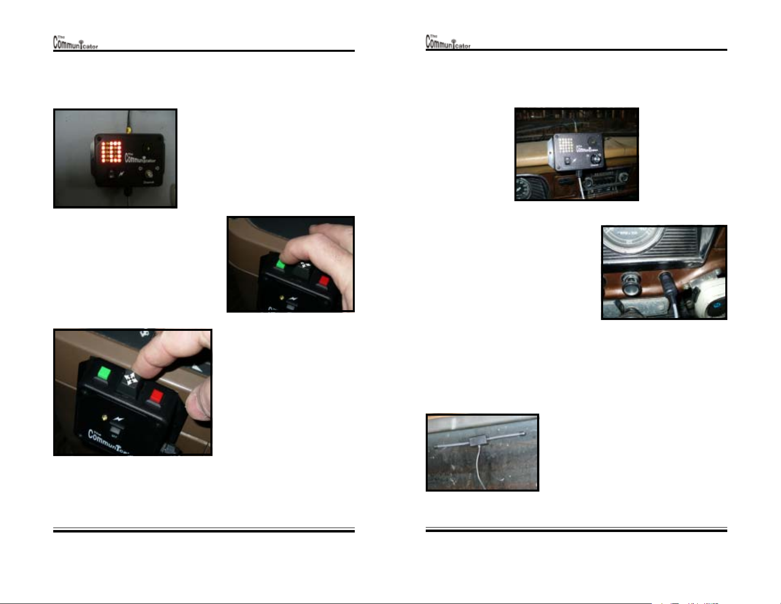
Testing the Receiver LEDs
Press the CHANNEL button on
the receiver within 1 second of
turning on the power. The receiver
Installation
Manual
Page 6
will sequence through the different
display symbols such as channel
numbers, directional arrows, etc.
Operators
Manual
Page 4
Model 201 Version 1.0
Model 201 Version 1.0
Programming the Channel
Each transmitter needs to be programmed to 1
of the 19 channels before using. The default
channel is 1 from the factory. Program each
transmitter to a different channel in a multitransmitter environment. To program the
channel of a transmitter, turn on and watch a
receiver for indication of the correct channel.
1) Press and hold the GREEN button while
turning on the power.
2) Hold the GREEN button until LED starts
to blink. (Approximate. 3 seconds)
3) Release the GREEN button.
4) Press the RED button to transmit the
current channel of the transmitter.
(Observe the channel on the receiver.)
5) Activate the JOYSTICK switch to
change to the next channel. Activate
the JOYSTICK only once for each
channel change. Each subsequent
activation of the JOYSTICK will
change to the next channel. Activating
and HOLDING the JOYSTICK will
change to the next channel, and
continuously transmit that channel.
Releasing the joystick will stop the
transmission. To retransmit see # 4.
8) Press the GREEN button to store the channel.
9) LED changes blink sequence to indicate the channel is stored.
10) Turn the power off and then on again without pressing any buttons for normal
operation.
Mounting the Receiver
Mount the receiver at a convenient location
so as to give the operator a good view. Plug
the power cable into a 12vdc lighter adapter.
If no lighter adapter is available cut the
adapter off and connect directly to a 12vdc
power source. The RED wire is positive(+)
and the BLACK wire is ground(-).
Mounting the Antenna
Connect the antenna cable and route the cable
safely to a spot on the window where it would be
in the best line of site with the harvester. Remove
the sticker from the antenna and attach it to a
clean spot on the window.
Installation
Manual
Page 7
Operators
Manual
Installation
Manual
Page 8
Operators
Manual
Page 5
Model 201 Version 1.0
Operating the Receiver
Changing Channels
1) Press the CHANNEL button.
2) The display shows the channel of the receiver for approximately 3 seconds.
3) Turn the channel button up or down to change channels.
4) The channel can only be changed while it is displayed.
5) The receiver automatically stores the new channel after the display goes blank.
Model 201 Version 1.0
Use the Communicator for combine harvestingUse the Communicator for combine harvesting
Use the Communicator for combine harvesting
Use the Communicator for combine harvestingUse the Communicator for combine harvesting
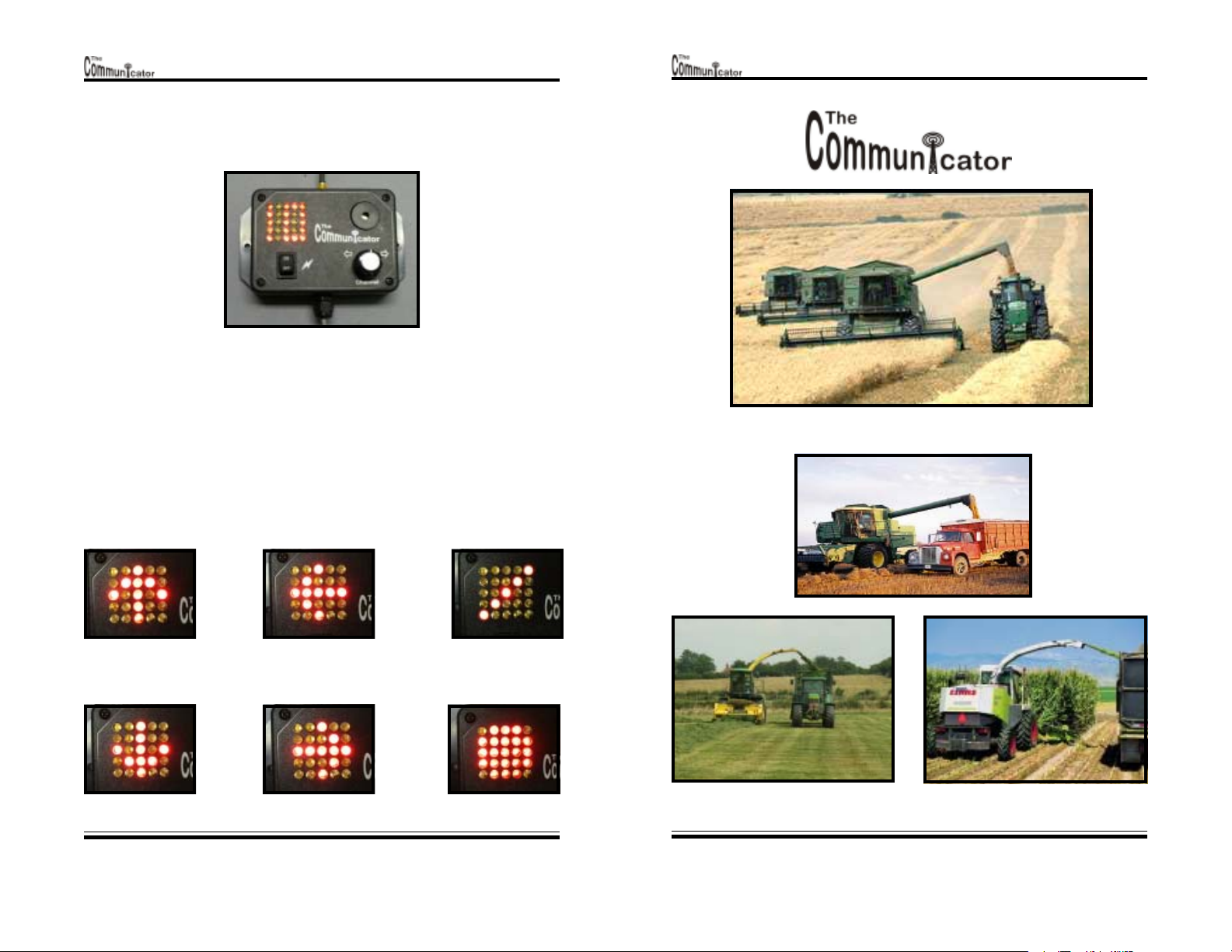
Operational Symbols
ForwardForward
Forward
ForwardForward
BackBack
Back
BackBack
Installation
Manual
LeftLeft
Left
LeftLeft
RightRight
Right
RightRight
Page 9
Go =Go =
Go =
Go =Go =
Rotating LineRotating Line
Rotating Line
Rotating LineRotating Line
StopStop
Stop
StopStop
Operators
Manual
Use the Communicator for silage harvestingUse the Communicator for silage harvesting
Use the Communicator for silage harvesting
Use the Communicator for silage harvestingUse the Communicator for silage harvesting
Installation
Manual
Page 10
Operators
Manual
Page 6

Model 201 Version 1.0
FCC Warning
This equipment has been tested and found to comply with the limits for a class B
digital device, pursuant to part 15 of the FCC Rules. These limits are designed to
provide reasonable protection against harmful interference in a residential
installation. This equipment generates, uses and can radiate radio frequency
energy and if not installed and used in accordance with the instructions, may cause
harmful interference to radio communications. However, there is no guarantee
that interference will not occur in a particular installation. If this equipment does
cause harmful interference to radio or television reception, which can be determined
by turning the equipment off and on, the user is encouraged to try to correct the
interference by one or more of the following measures:
-Reorient or relocate the receiving antenna.
-Increase the separation between the equipment and receiver.
-Connect the equipment into an outlet on a circuit different from that to which the
receiver is connected.
-Consult the dealer or an experienced radio/TV technician for help.
In order to maintain compliance with FCC regulations, shielded cables must be
used with this equipment. Operation with non-approved equipment or unshielded
cables is likely to result in interference to radio and TV reception. The user is
cautioned that changes and modifications made to the equipment without the
approval of the manufacturer could void the user's authority to operate this
equipment.
Industry Canada Compliance Statement
ICES-003 This Class B Digital apparatus complies with Canadian ICES-003
“Operation is subject to the following two conditions: (1) this device may not cause
interference, and (2) this device must accept any interference, including interference
that may cause undesired operation of the device.”
“To reduce potential radio interference to other users, the antenna type and its gain
should be so chosen that the equivalent isotropically radiated power (EIRP) is not
more than that required for successful communication”.
Installation
Manual
Page 11
Operators
Manual
Time Tronics Inc.
Box 580
Pincher Creek, AB. T0K1W0
Bus: 403-627-2100
Fax: 403-627-5557
Model IDF-201 Ver 1.0 January 2006
 Loading...