

Timespace X300 Instruction Manual

Timespace Technology Ltd Blackstone Road Huntingdon Cambridgeshire PE29 6TT UK
t: +44 (0)1480 414147 f: +44 (0)1480 414146 e: mail@tspace.co.uk www.tspace.co.uk
®
X300
Instruction Manual
Designed and Manufactured in the UK
The latest version of the X300 Manual is available online; www.tspace.co.uk
X200 Operating Software V2.0.1
X300 Operating Software V1.3.2
V400 Operating Software V1.2.3
PCLink Suite V7.5
PCLink200 V1.8.2
PCPlayer V1.8.2
RemoteLink V1.8.2
X-Communicate V1.8.2
Kstation V1.0.0.4
SafetyLink V1.0
ImageLink V1.0
LANLink V4.0
© 30th April 2015

2
Contents
SAFETY ..................................................................................................................................................... 5
ENVIRONMENTAL ................................................................................................................................... 5
SHOCK AND VIBRATION ..................................................................................................................... 5
EMC ....................................................................................................................................................... 5
CONFORMITY ...................................................................................................................................... 5
RECYCLING .......................................................................................................................................... 5
EC DECLARATION OF CONFORMITY ............................................................................................... 6
E11 TYPE APPROVAL ......................................................................................................................... 7
SYSTEM OVERVIEW ............................................................................................................................. 10
X300 Front Panel ................................................................................................................................ 11
SD Card Compatibility ......................................................................................................................... 11
X300 Rear panel, common connections ............................................................................................. 13
X300-4 Rear Panel .............................................................................................................................. 15
X300-16 Rear Panel ............................................................................................................................ 16
X300 DIGITAL RECORDER ................................................................................................................... 18
INSTALLATION ................................................................................................................................... 19
T408 VEHICLE KIT ............................................................................................................................. 20
SERVICE AND FAIL LED ................................................................................................................... 25
PROGRAMMING................................................................................................................................. 26
HELP SCREENS ................................................................................................................................. 26
SOFTWARE UPDATES ...................................................................................................................... 26
SOFTWARE UPDATES - PCLink ....................................................................................................... 27
LANGUAGE SELECTION ................................................................................................................... 28
VIDEO STANDARD - PAL / NTSC...................................................................................................... 28
FILE SYSTEM ..................................................................................................................................... 28
VIDEO COMPRESSION ..................................................................................................................... 29
AUDIO ................................................................................................................................................. 30
PC ACCESS PRECAUTIONS ............................................................................................................. 31
PC NETWORK ACCESS .................................................................................................................... 31
WATERMARK ..................................................................................................................................... 32
SEQUENCING .................................................................................................................................... 32
WATERMARK FILE ............................................................................................................................ 32
GPS ..................................................................................................................................................... 33
REMOTE OPERATION (GSM / LAN / Wifi / 3G) ................................................................................ 34
RS232 EXTERNAL CONTROL ........................................................................................................... 36
X300 MENU SYSTEM ............................................................................................................................. 42
MAIN MENU ........................................................................................................................................ 43
NORMAL RECORDING ...................................................................................................................... 44

3
ALARM RECORDING ......................................................................................................................... 46
ALARM INPUTS .................................................................................................................................. 47
ALARM OUTPUT ................................................................................................................................ 48
ALARM CYCLER................................................................................................................................. 49
SD CARD ............................................................................................................................................ 50
SD CARD RECORDING ..................................................................................................................... 51
SD CARD FILE COPY ........................................................................................................................ 52
SHOT RECORDING ........................................................................................................................... 53
MOTION DETECTION ........................................................................................................................ 54
PRE-MOTION RATE RECORDING .................................................................................................... 55
AUDIO RECORDING .......................................................................................................................... 55
RECORDED FILES ............................................................................................................................. 57
VIDEO OUTPUT.................................................................................................................................. 58
MAIN VIDEO SWITCHER ................................................................................................................... 58
AUX VIDEO SWITCHER ..................................................................................................................... 59
TIME AND DATE ................................................................................................................................. 60
CAMERA SETTINGS .......................................................................................................................... 61
FILE SYSTEM ..................................................................................................................................... 62
SYSTEM INFO .................................................................................................................................... 63
PASSWORD ........................................................................................................................................ 64
POWER OPTIONS .............................................................................................................................. 65
RESET ................................................................................................................................................. 66
EXTERNAL EQUIPMENT ................................................................................................................... 67
LAN ...................................................................................................................................................... 68
GPS ..................................................................................................................................................... 69
GSENSOR ........................................................................................................................................... 70
GSM / REMOTE .................................................................................................................................. 71
SMS MESSAGES ............................................................................................................................... 72
HEALTH OVER SMS .......................................................................................................................... 73
IMAGES OVER SMS .......................................................................................................................... 74
PTZ ...................................................................................................................................................... 75
SMTP EMAIL ....................................................................................................................................... 76
WEB SERVER..................................................................................................................................... 77
ADVANCED ......................................................................................................................................... 78
LOAD SYSTEM UPGRADE ................................................................................................................ 80
TIMESPACE REVIEWER ....................................................................................................................... 81
FUNCTION ...................................................................................................................................... 81
MENU NAVIGATION CONTROLS .................................................................................................. 82
PLAYBACK & RECORDING ........................................................................................................... 83

4
CAMERA SWITCHER ..................................................................................................................... 84
PTZ CONTROLS ............................................................................................................................. 85
SETTING PTZ PRESETS ............................................................................................................... 85
PTZ MODES .................................................................................................................................... 86
USB INTERFACE KIT ............................................................................................................................. 87
PCLINK SUITE ........................................................................................................................................ 88
WARNINGS ............................................................................................................................................. 89
APPEXDIX 1 – Health SMS Message Format ........................................................................................ 90
APPEXDIX 2 – Splash Screen ................................................................................................................ 93
APPEXDIX 3 – Transport for London IBUS diagnostic interface ............................................................ 94

5
SAFETY
The X300 is designed to be powered from an external power source which complies with the Low
Voltage Directive (73/23/EEC).
The X300 is designed for indoor use in the temperature range 0° to 50°C, 20% to 80% RH (noncondensing).
ENVIRONMENTAL
The X300 may be operated in ambient temperatures from 5°C to 40°C. This specification applies in still
air, with the X300 mounted horizontally and ambient temperature measured 15cms above the centre of
X300.
If the X300 is to be mounted in an enclosure is important that the internal temperature inside the
enclosure does not exceed the specification above and any new enclosure design should be tested.
SHOCK AND VIBRATION
Due to the nature of hard disk drives it is essential that the X300 is isolated from vibration and shock as
much as possible. Consideration should be paid to the mounting position so that the levels of shock and
vibration that may be encountered are minimized.
In situations where some exposure to shock and vibration are unavoidable it is strongly advised that the
T406 Anti-Vibration System is used. This system is specifically designed to isolate the X300 from
shock and vibration. Further details and fitting instructions can be found in the Anti-Vibration Kit section
of this manual.
EMC
The X300 complies with the relevant EEC, Automotive „E‟ Mark and EMC standards for this type of
product.
CONFORMITY
EMC Conformity (CE Mark); Meets the European Council Directive 89/336/EEC (EMC Directive)
relating to EMC Emissions - EN61000-6-3(2001) and EMC Immunity – EN61000-6-1(2001).
EMC Conformity (E Mark); Meets the Type Approval requirements of European Commission Directive
95/54/EC.
CFR47:2009 Class A, Part 15 - Radiated Emissions and Conducted Emissions.
RECYCLING
When the product has reached its end of life and requires disposal, recycling instructions are available
upon request.

6
EC DECLARATION OF CONFORMITY
EC Declaration of Conformity (CE)
We Timespace Technology Ltd
Blackstone Road
Huntingdon
PE29 6TT
United Kingdom
declare that the
X300 Digital Video Recorder
Meets the intent of the European Council Directive 89/336/EEC referred to as the
Electromagnetic Compatibility (EMC) Directive. The product conforms to the following
standards which have been listed in the Official Journal of the European Union.
EMC
Emissions - EN55022:2006 + A1
Information technology equipment – Radio disturbance characteristics – Limits and methods
of measurement.
Conducted - EN55024:1998 +A1 +A2
Information technology equipment – Immunity characteristics – Limits and methods of
measurement.
…………………………………………………………………
Dr ROBERT HEYLEN
TECHNICAL DIRECTOR
1st December 2010

7
E11 TYPE APPROVAL
VCA Headquarters
1 The Eastgate Office Centre
Eastgate Road Bristol, BS5
6XX United Kingdom
Switchboard: +44 (0) 117 951 5151
Main Fax: +44 (0) 117 952 4103
Email: enquiries@vca.gov.uk Web:
www.vca.gov.uk
THE UNITED KINGDOM VEHICLE APPROVAL AUTHORITY
COMMUNICATION CONCERNING THE TYPE-APPROVAL (1), EXTENSION OF TYPEAPPROVAL (1), REFUSAL OF TYPE-APPROVAL(1), WITHDRAWAL OF TYPEAPPROVAL
(1), OF A TYPE OF COMPONENT/SEPARATE TECHNICAL UNIT(1) WITH REGARD TO
RADIO INTERFERENCE SUPPRESSION DIRECTIVE 72/245/EC, AS LAST AMENDED
BY DIRECTIVE 2009/19/EC.
Type Approval No: e11*72/245*2009/19*5917*00
Reason for Extension: Not applicable EC type-approval
mark to be affixed on ESA: e11 03 5917
EAL231520 An executive agency of the Department for Transport December
2009 Issue 1
SECTION I
0.1.
Make (trade name of manufacturer): Timespace Technology Limited
0.2.
Type and general commercial description(s): X300 Digital Video Recorder
0.3.
Means of identification of type, if marked on the
vehicle/component/separate technical unit (1) (2): Self adhesive label
containing the part number
0.3.
1.
Location of that marking: Top left of the digital video recorder
0.5.
Name and address of manufacturer:
Timespace Technology Limited
Blackstone Road
Huntingdon
Cambridgeshire
PE29 6TT
United Kingdom
Name and address of authorised representative, if any; Not applicable

8
72/245/EC AS LAST AMENDED
0.7. In the case of components and separate technical units, location and method
of affixing of the EEC approval-mark: Self adhesive label on the bottom of the digital
video recorder
0.8. Address(es) of assembly plant(s): As 0.5 above
SECTION II
1. Additional information (where applicable): See Appendix
2. Technical service responsible for carrying out the tests: MIRA, Nuneaton
3. Date of test report: 22 June 2011
4. Number of test report: 1029232#03
5. Remarks (if any): See Appendix
6. Place: BRISTOL
7. Date: 10 JULY 2011
8. Signature:
A. W. STENNING Head of
Technical and Quality Group
9. The type approval file deposited at the Administrative Service having delivered
the type approval may be obtained on request
(1) Delete where not applicable.
(2) If the means of identification of type contains characters not relevant to describe
the vehicle, component or separate technical unit types covered by this typeapproval certificate such characters shall be represented in the documentation by
the symbol „?‟(e.g. ABC??123??).
(3) As defined in Annex IIA to Directive 70/156/EEC.
EAL231520 An executive agency of the Department for Transport December
2009 Issue 1

9
72/245/EC AS LAST AMENDED
APPENDIX
of EC Type Approval Certificate No: e11*72/245*2009/19*5917*00 concerning
the type approval of an electric/electronic subassembly with regard to Directive
72/245/EEC as last amended by Directive 2009/19/EC
1. Additional information:
1.1. Electrical system rated voltage: 12 V dc
1.2. This ESA can be used on any vehicle type with the following restrictions:
Negative earth vehicles only
1.2.1. Installation conditions, if any: Manufacturer‟s instructions to be followed
1.3. This ESA can only be used on the following vehicle types: Not applicable
1.3.1. Installation conditions, if any: Not applicable
1.4. The specific test method(s) used and the frequency ranges covered to
determine immunity were: (please specify precise method used from Annex IX): Not
applicable
1.5. Laboratory accredited to ISO 17025 and recognised by the Approval
Authority (for the purpose of this Directive) responsible for carrying out the test.
MIRA, Nuneaton, United Kingdom
5. Remarks: None
EAL231520 An executive agency of the Department for Transport December
2009 Issue 1
10
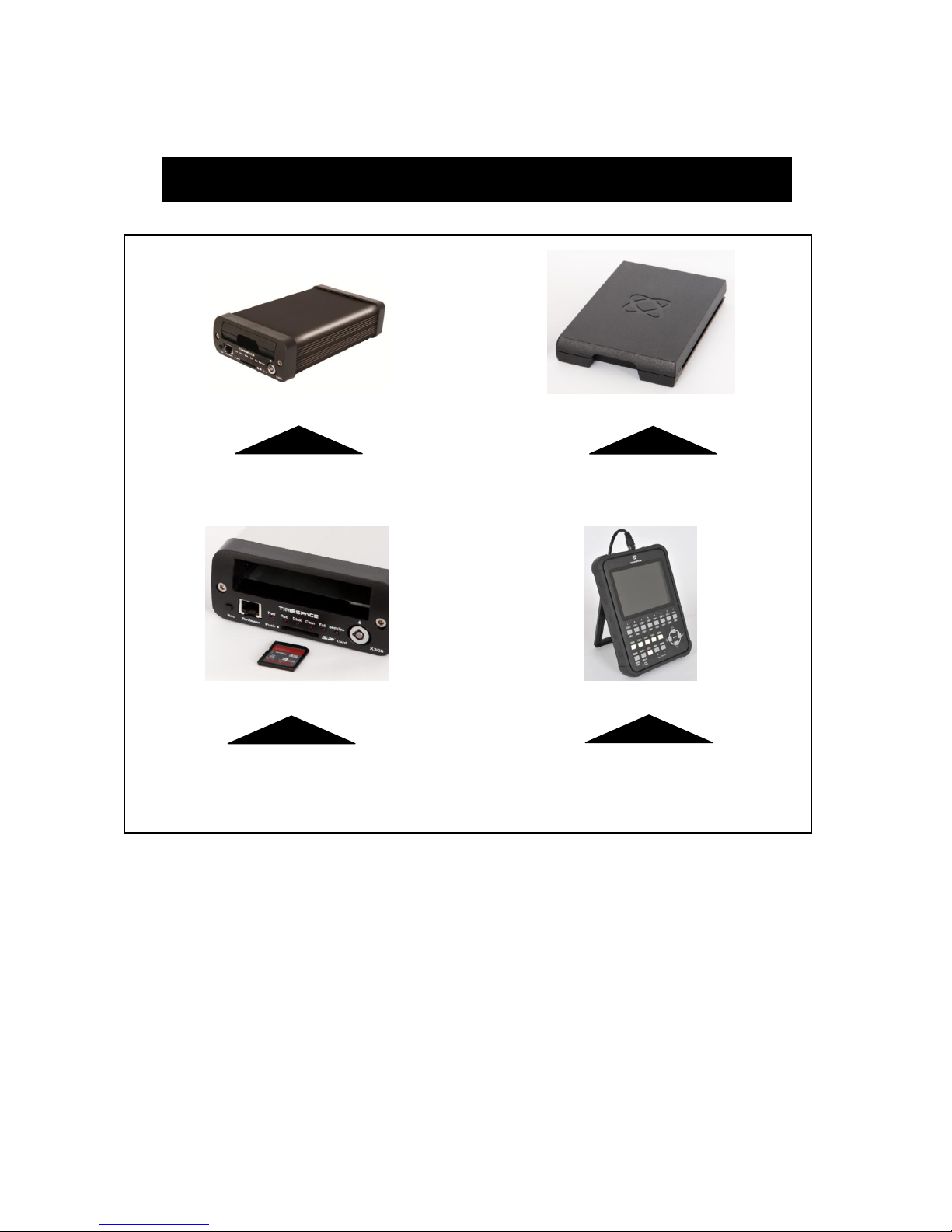
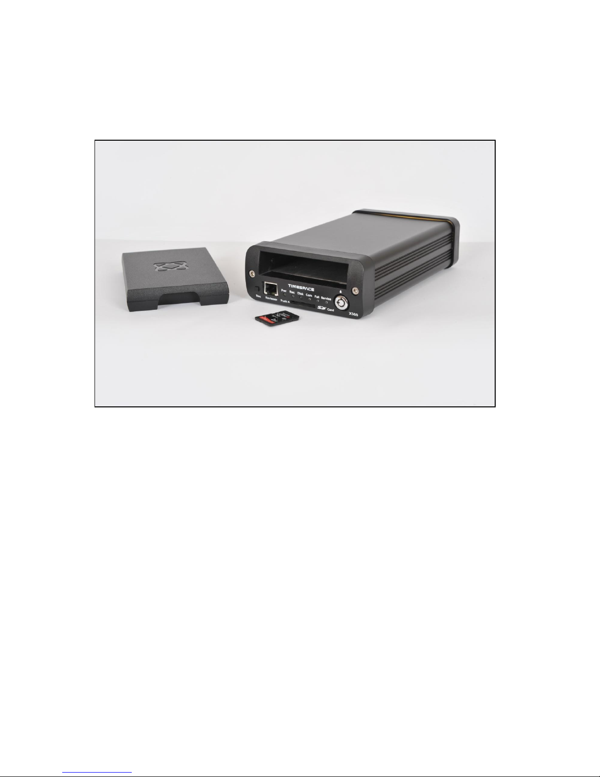
SYSTEM OVERVIEW
X300 DIGITAL VIDEO / AUDIO RECORDER
REMOVABLE HARD DISK CARTRIDGE
REMOVABLE SD CARD FOR DUAL
RECORDING & DOWNLOAD (OPTIONAL)
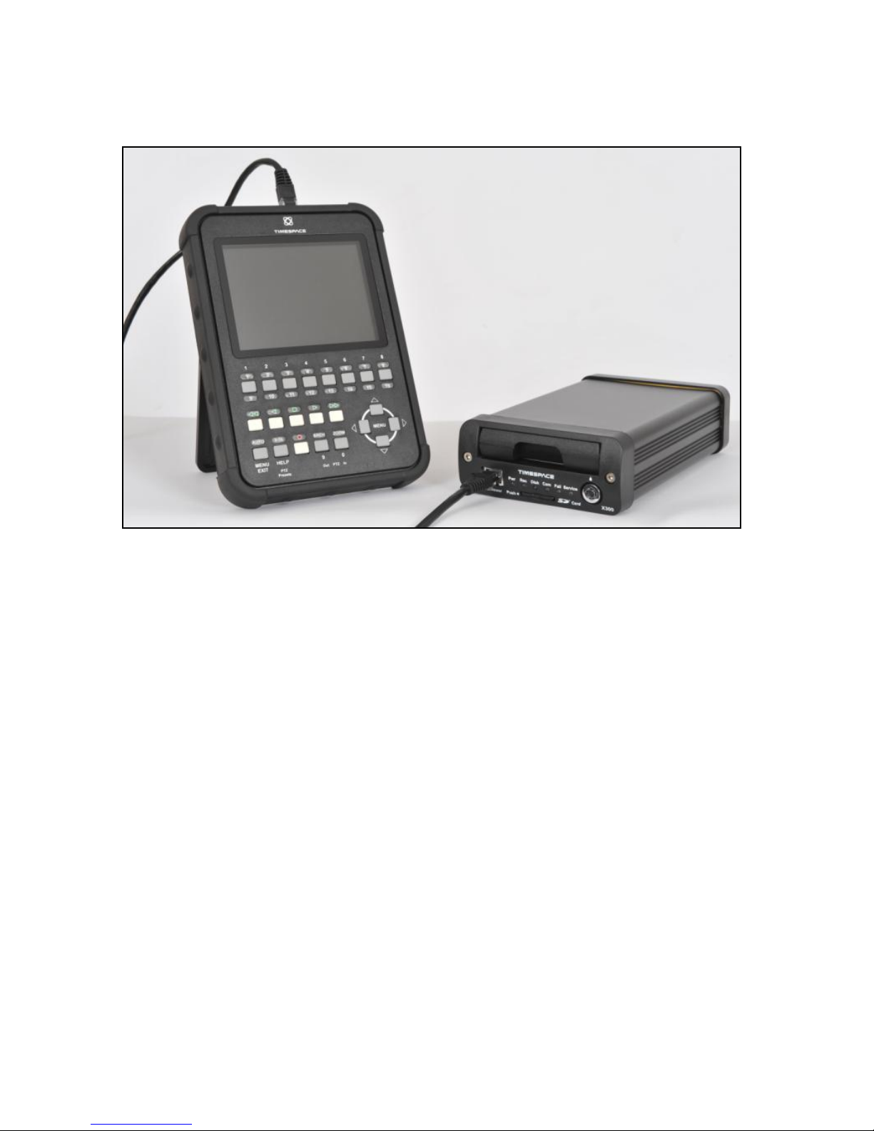
TIMESPACE REVIEWER / PROGRAMMER
The X300 is a digital video/audio surveillance recorder for use in covert, portable and mobile
applications.
Recordings are made on a removable hard disk cartridge inserted in the X300. Optionally recordings
can be written to a removable SD card.
The recordings can be accessed by connecting the cartridge to a PC using the USB interface kit.
Timespace PCLink200 application is a proprietary reading and archiving software package.
The Timespace Reviewer is used to program the menu settings on X300, to check camera views and to
review recordings on the installed X300 Hard Disk Cartridge. Recording can continue during this
reviewing process.
X300 DIGITAL VIDEO/AUDIO RECORDING SYSTEM
11
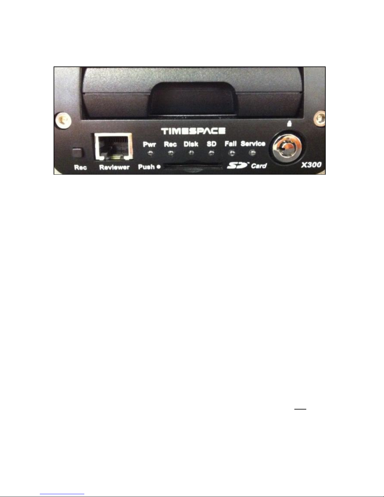
X300 Front Panel
RECORD BUTTON
Turns configured recording mode on and off. Button can be disabled within menu settings.
LED’s
Pwr - Illuminated when the X300 is powered (Green LED).
Record - Illuminated Red when the X300 is recording (flashing when in Motion Detect mode).
Disk - Pulses Green/Red when the X300 is reading/writing to/from the Cartridge or SD card.
SD - Pulses Orange when the X300 is reading/writing to/from the SD card.
Fail - Illuminated Red when any of the Fail conditions are met (refer to Service / Fail page).
Service - Illuminated Orange when any of the Service conditions are met (refer to Service / Fail
page)
At Power On - All LED‟s will illuminate whilst the X300 initialises and will remain lit during system
check (menu disabled) until the unit is operational. Once operational only the Pwr LED will remain
illuminated unless recording is taking place.
CARTRIDGE LOCK
Locked - Securely locks the removable cartridge in place and enables it for use.
Unlocked - Turns off the cartridge, releasing it for removal.
SD CARD
The X300 supports a single SD card for two configurable functions:
Dual Recording - The X300 menu settings can be configured to record up to 25 images per second to
the SD card in addition to primary images per second being recorded to the cartridge.
All additional data for example audio and gps are also included within the SD recorded
files.
File Download - Files that are recorded on the X300 Cartridge can be selected and copied to the SD
card for review on a PC.
SD Card Compatibility The X300 supports SanDisk SDHC Ultra or Extreme cards only. Sizes
include 4GB, 8GB, 16GB and 32GB. Both 15 and 30MB/s SD cards are compatible however for best
Audio playback results, 30MB/s is recommended.
12
TIMESPACE REVIEWER CONNECTOR
Connect the Timespace reviewer to X300 Reviewer socket using a standard RJ45 Ethernet cable.
Signals for this connector are as follows:
1 Video out
2 Video ground
3 Audio ground
4 RS232 Rx
5 RS232 Tx
6 Audio out (line level)
7 Power ground
8 12V
The 12V is supplied to the Reviewer from the X300. NB using greater than 12V may damage both the
X300 and the Reviewer. Never connect a laptop or PC to the front panel Reviewer socket, this will
damage the laptop/PC.
13
X300 Rear panel, common connections
RS232 CONNECTOR
9 way male D-type connector (DB9) which can be used to support 1 or 2 RS232 peripherals.
PIN TYPE I/O TYPE
3 TD, Transmit Data > Serial Data
2 RD, Receive Data < Serial Data
7 RTS, Request to send > Handshaking
8 CTS, Clear to send < Handshaking
4 DTR, Data terminal ready > X300 outputs 5V
6 DSR, Data set ready < Ignored by X300
1 DCD, Data carrier detect < Detect modem status
9 RI, Ring Indicator < Ignored by X300
5 GND, Ground
> X300 output
< X300 input
Using a conventional cable (DB9 male to DB9 female straight through (1-1, 2-2, 3-3 etc.)) the X300 can
be connected to a modem. Alternatively, two RS232 peripherals such as GSM modem and GPS device
can be connected simultaneously. Here is an example of the wiring;
PIN TYPE I/O TYPE
Device 1 (Modem)
3 TD, Transmit Data > Serial Data
2 RD, Receive Data < Serial Data
7 RTS, Request to send > Handshaking
8 CTS, Clear to send < Handshaking
1 DCD, Data carrier detect < Detect modem status
5 GND, Ground
Device 2 (GPS)
4 5V, Supply (500mA max) > Power
9 RD, Receive Data < Serial Data
5 GND, Ground
> X300 output
< X300 input
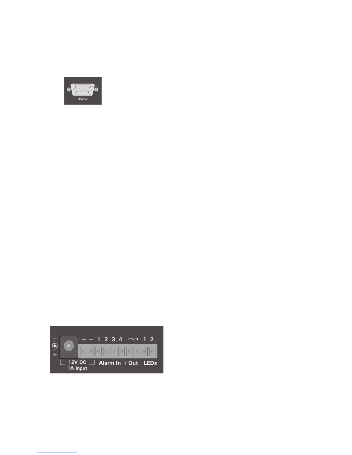
INPUT/OUTPUT CONNECTOR
10 way screw terminal block.
The X300 requires 12V regulated power. This can be applied to either via 12V DC jack socket or 12V
screw terminals. NB: Do not use both power inputs simultaneously.
Connect alarm inputs 1, 2, 3 and 4 to - terminal if closed or for open circuit leave open.
Connect alarm output to Out terminal pair.
Connect LED 1 between + and terminal LED 1, including a series resistor to limit current.
14
Connect LED 2 between + and terminal LED 2, including a series resistor to limit current.
Terminals LED 1 and LED 2 are high impedance (LAMP/LED off) or 0V (LAMP/LED on)
LED outputs 1 and 2 can be menu assigned to duplicate any of the 4 front panel LEDs (power, record,
service and fail).
ETHERNET CONNECTOR
Connect via a standard RJ45 Ethernet cable (straight i.e. pins 1-1, 2-2, 3-3 etc.) to Ethernet hub,
switch, router, wireless LAN adaptor or 3G modem.
Internal Connections: 1 Tx+, 2Tx-, 3 Rx+, 4 NC, 5 NC, 6 Rx-, 7 NC, 8 NC
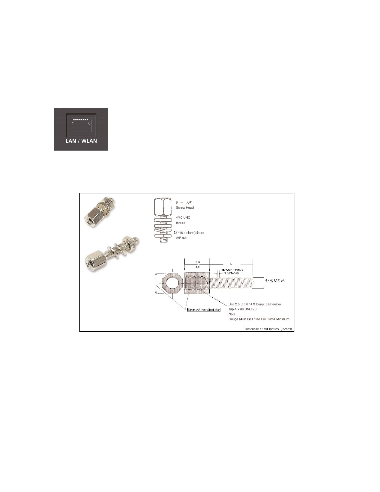
The RS232 and 25 way D-type connectors use a 4-40 UNC Thread type Jack Posts. Farnell PN:
1099010:
15
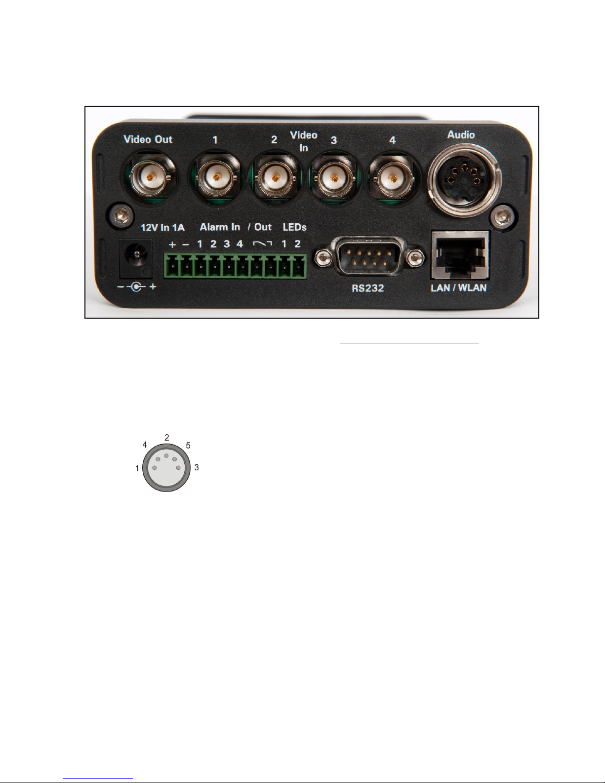
X300-4 Rear Panel
Power, I/O, RS232 and LAN connections are described under Rear panel Common connections.
VIDEO CONNECTORS
1 BNC video output
4 BNC video inputs
AUDIO CONNECTOR
5 pin 180° female DIN connector (DIN 41524)
Pin
1 Audio input 1 (left)
4 Audio input 2 (right)
2 Audio GND
5 Audio output 2 (right)
3 Audio output 1 (left)
The audio signals are at line level. A 5 pin DIN to 4 way RCA phono harness can be readily purchased
from a number of suppliers. A locking connector could be used to secure the DIN in place.
16
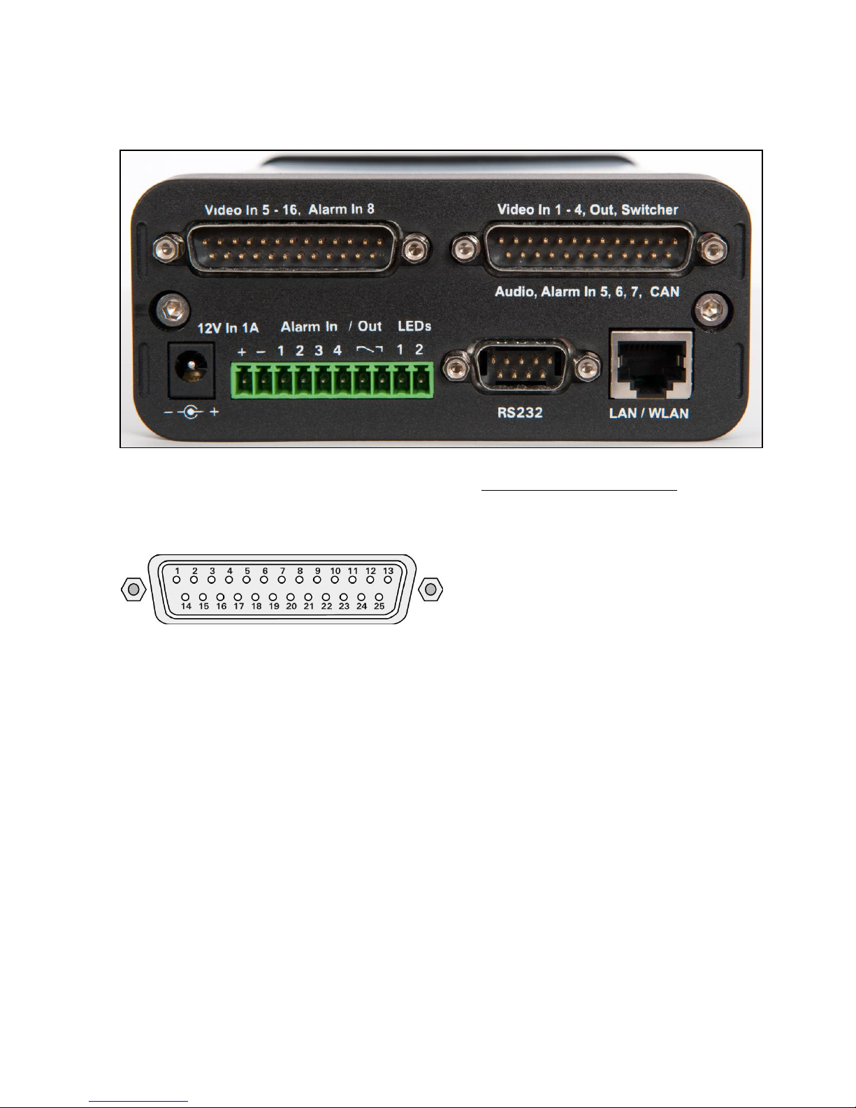
X300-16 Rear Panel
Power, I/O, RS232 and LAN connections are described under Rear panel Common connections.
Pin numbering of both 25 Way Male D type connectors on X300 (looking at rear panel).
Video 5 - 16, Alarm In 8 Connector
Pin Pin
1 Video GND In 5 14 Video In 5
2 Video GND In 6 15 Video In 6
3 Video GND In 7 16 Video In 7
4 Video GND In 8 17 Video In 8
5 Video GND In 9 18 Video In 9
6 Video GND In 10 19 Video In 10
7 Video GND In 11 20 Video In 11
8 Video GND In 12 21 Video In 12
9 Video GND In 13 22 Video In 13
10 Video GND In 14 23 Video In 14
11 Video GND In 15 24 Video In 15
12 Video GND In 16 25 Video In 16
13 Alarm In 8

17
Video 1 - 4, Out, Switcher, Audio, Alarm In 5, 6, 7, CAN Connector
Pin Pin
1 Video GND In 1 14 Video In 1
2 Video GND In 2 15 Video In 2
3 Video GND In 3 16 Video In 3
4 Video GND In 4 17 Video In 4
5 Video GND Main Out 18 Video Main Out
6 Video GND Switcher Out 19 Video Switcher Out
7 Audio GND Out 2 (right) 20 Audio Out 2 (right)
8 Audio GND Out 1 (left) 21 Audio Out 1 (left)
9 Audio GND In 1 (left) 22 Audio In 1 (left)
10 Audio GND In 2 (right) 23 Audio In 2 (right)
11 Alarm In 5 24 Alarm In 6
12 CAN L 25 CAN H
13 Alarm In 7
X300-16 Cable Harness Recommended Specification; A common cable harness can be used for both
25 Way D type connections on the X300-16
Connector 25 Way Female D type
Shell Recommended max overall width 56mm (the two 25 way connectors are 57mm apart)
Cables 12 individual RG179 cables of suitable length.
Connections Shield pin Core Pin
Cable 1 1 14
Cable 2 2 15
Cable 3 3 16
...
Cable 12 12 25
Pin 13 not connected.
In order to meet the EMC standards with which the X300 is compliant it is important that shielded
cables are exclusively used. All of the signal grounds should be common inside the D-Type connector
and connected to a metal back-shell in order that the cable run and D-Type connector are shielded.
18
X300 DIGITAL RECORDER
19
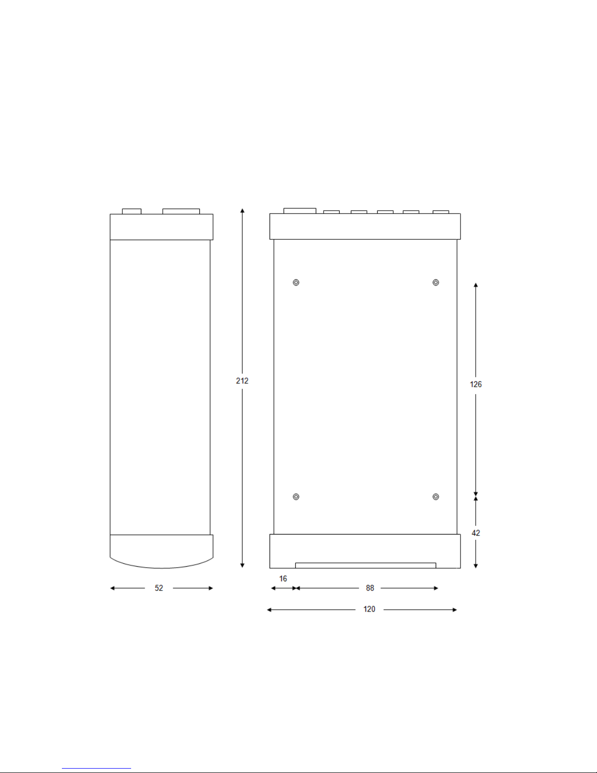
INSTALLATION
The X300 can be used free-standing or it can be mounted using the 4 x threaded holes on the
underside - mounting screw size M4, 0.7 Pitch, 12mm).
The X300 requires 12V regulated power. This can be applied to either via 12V DC jack socket or 12V
screw terminals. NB: Do not use both power inputs simultaneously. Cameras and other external
equipment should be connected / wired to the X300 before power is applied.
Mechanical Data / fixing specification (measurements shown in mm);
20
T408 VEHICLE KIT
The following instructions are based on the Timespace X200 DVR, therefore some measurements will
vary slightly from the X300 – see INSTALLATION page of this manual for exact X300 mechanical data.
For use in mobile installations subject to shock and vibration. Please adhere to the following
instructions for the installation of the Vehicle Kit. Failure to do so may result in the Mounting System
not working correctly.
Inventory of Parts
The Vehicle Kit consists of the following parts;
QTY Description
4 Wire Rope Mounts
1 Stabiliser Coupling
8 M4 x 12mm Counter-Sunk Hex-Head Screws
In addition you will require a standard „L‟ shaped hex key. This is essential, as when all of the other
screws have been tightened, there is no room for any other tool to tighten the front lower pair of screws.
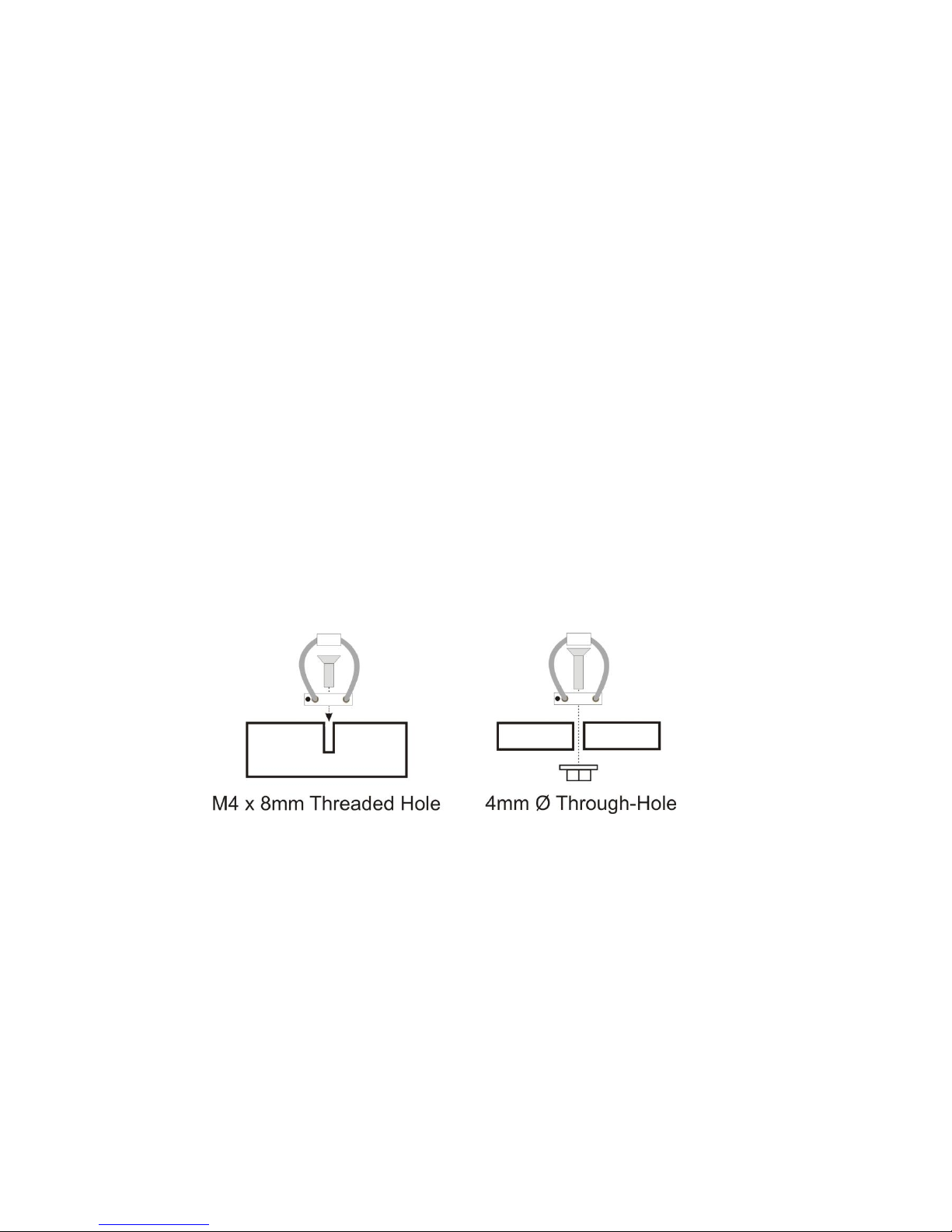
Mounting Hole Preparation
Drill four mounting holes to attach the Wire Rope Mounts. If you intend to use the M4 x 12mm screws
into blind holes, then the holes will have to be drilled and tapped to accept an M4 screw, with a thread
depth of no less than 8mm.
If mounting the Wire Rope Mounts through a metal plate, then longer screws may have to be used in
order to allow a washer and nut to be attached on the other side of the plate. The length of these
screws will have to be chosen depending on the thickness of the plate and the height of the washer and
nut.
Please note that any screw used for mounting the wire rope mounts to an enclosure surface must have
an M4 thread and have a counter-sunk hex-head.
21
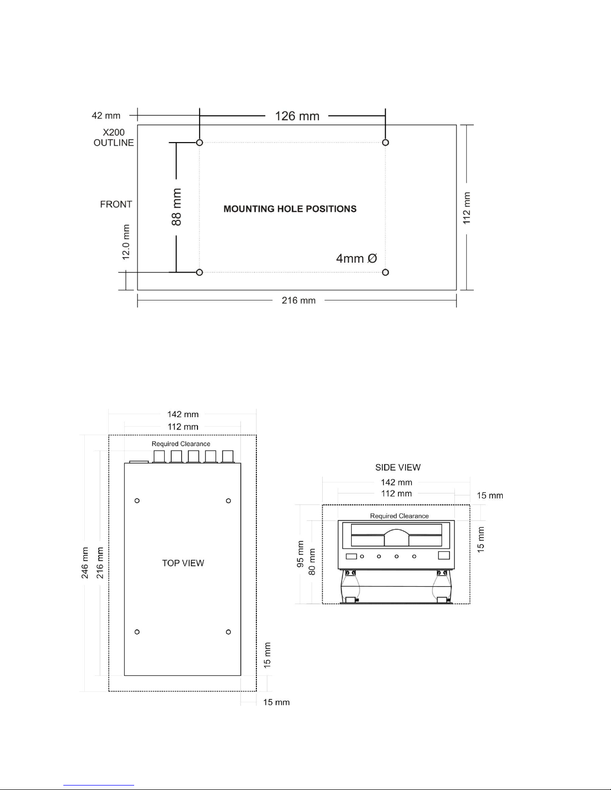
Mounting Hole Location
The mounting holes must be drilled on 126mm and 88mm centres.
Total Mounting Volume Required
It is necessary to allow a minimum clearance of at least 15mm around the body of the X200 when
mounted on the T408 Vehicle Kit. This is to allow free movement of the X200 on the anti vibration
mounts and to prevent collision with either the enclosure or peripheral systems due to vertical and
lateral movement under extreme shock and vibration conditions.
Please note that when using the T407
Cartridge Lock an extra 20mm of
Clearance must be allowed at the front

22
Cable Installation
Please note that when installing cables to the rear of the X200 it is important not to arrange or clamp
them in such a way as to impede the free movement of the rear anti-vibration mounts.
Installation Procedure
It is advised that some form of thread-lock compound should be used on the screws securing the wire
rope mounts to both the X200 and mounting surface. This is in order to prevent loosening due to
vibration. WARNING - Ensure only a small amount of adhesive is added to the screw points. Excessive
amounts will leak onto the circuit board and damage components.
Attach the Wire Rope Mounts to the X200 with four of the countersunk M4 hex-head screws provided
and L-shaped hex key. When attaching the rear pair of mounts please ensure that the stabilizer is
„sandwiched‟ between the mounts and the X200 by aligning the stabilizer holes with the mounting holes
in the X200.
Please note that the „open‟ end of the C-shaped plastic stabiliser should be attached to the rear wire
rope mounts and face backward.
Once all of the Wire Rope Mounts have been securely attached to the X200, use a pair of countersunk
M4 hex-head screws to attach the bottom „feet‟ of the front Wire Rope Mounts to the mounting
surface/enclosure.
Secure the lower „feet‟ of the rear Wire Rope Mounts to the mounting surface/enclosure using the
remaining pair of countersunk M4 hex-head screws and a standard L-shaped hex key. Ensure that the
stabilizer is „sandwiched‟ between the lower feet and the mounting surface/enclosure by screwing
through the Wire Rope Mount feet, then the stabilizer and into the mounting surface/enclosure.
23
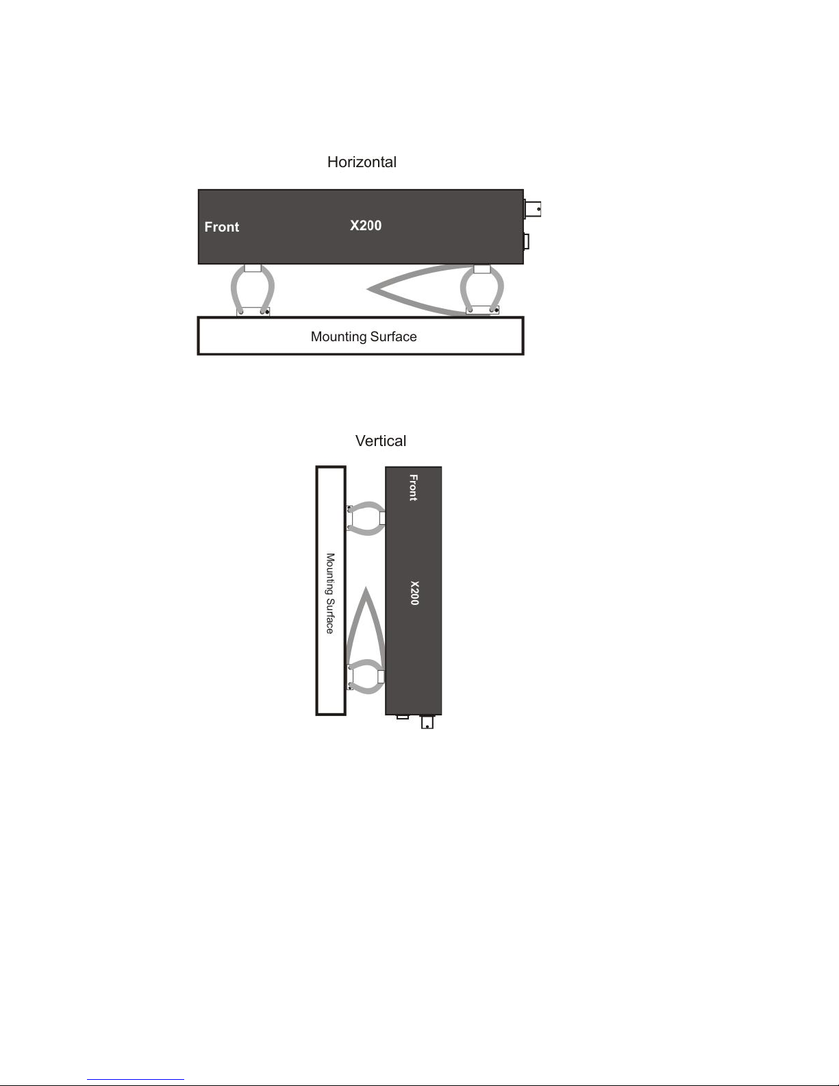
Orientation of Unit
The X200 should be mounted in the following horizontal orientation. This is strongly advised for
maximum vibration and shock isolation.
If it is not possible to mount the X200 in the horizontal orientation then the following vertical orientation
may be used.
It must be noted however that this vertical orientation is not as effective at isolating the X200 from
vibration and shock as the horizontal orientation.
The position of the plastic stabiliser, screw types and assembly order remain the same for this mounting
orientation.
The X200 must never be mounted by hanging it upside down from a horizontal surface when using this
mounting system.

24
Installation spare parts list
AUDIO CONNECTOR
Locking Nickel plated finish; Deltron part number 590-0500 or Farnell part no. 119-3833.
Locking Black finish; Deltron part number 591-0500 or Farnell part no. 119-3828.
POWER CONNECTOR
2.1mm jack socket (requires 2.5 x 5.5 x 9.5mm DC); Farnell part no. 224923.
Right angle 2.1mm jack socket; CPC part no. AV15499.
GREEN BLOCK
Input/Output connector; Farnell part no. 9632794.
25 WAY D TYPE
Farnell 1099054 Multicomp
9 WAY RS232
Farnell 1099052 Multicomp

25
SERVICE AND FAIL LED
The Service and Fail LED‟s on the X300 front panel give a positive indication that a system fault has
occurred. If the Service LED is lit then the system will most likely be functional but may not be
performing as intended. An example may be one of the cameras has failed. If the Fail LED is lit then
the system will not be functioning and requires immediately attention. An example may be that the hard
disk cartridge has failed. The Service/Fail conditions are stored on the X300 for review. Each condition
has an identifiable code and associated description. The service log can be viewed here; SETTINGS
MENU > ADVANCED > VIEW SERVICE LOG menu. The LED will remain lit and the problem which
caused the Service LED to light will be listed in the log until the log is reset by selecting RESET
SERVICE LOG.
SERVICE CODE
CODE DESCRIPTION
POSSIBLE ACTION
101-116
Open circuit. No current on power input to camera ** and no
camera signal.
Check Camera & Cables
201-216
Short circuit. Over-current on power input to camera ** and no
camera signal.
Check Camera & Cables
301-316
No signal. Camera disconnected for cameras **.
Check Camera & Cables
811
CAM:DISCONNECTED CAMERA
Check Camera & Cables
815
SYS:TIME ERROR. The real time clock was out of sync by
more than +-10 seconds when the time was updated over GPS
/ LAN.
Check / update system Time.
817
SMS:MODEM SEND ERROR
Check SIM Card/Cable/Power
818
SMS:DIAL OUT FAIL
Check SIM Card/Cable/Power
819
SYS:SMTP FAIL
SMTP error - failed to send email.
840
CAM:INTERMITTENT CAMERA
Camera disconnect detected more than four
times - suspect intermittent camera
863
USR:LOG RESET
System Log Reset By User. No action, for
information only.
864
HDD:DELETE ALL FILES FAILURE
HDD delete all rec files failed (must have been an
unscheduled reboot during the process).
865
HDD:SECURE DISK WIPE FAILURE
HDD card secure card wipe failed (must have
been an unscheduled reboot during the process).
866
SD:DELETE ALL FILES FAILURE
SD card delete all rec files failed (must have
been an unscheduled reboot during the process).
867
SD:SECURE CARD WIPE FAILURE
SD card secure card wipe failed (must have been
an unscheduled reboot during the process).
900
Failure to Write Packet(s) Hard Disc. Recording is not possible.
Check disk
901
Failure to Read Packet(s) Hard Disc. Playback is not possible.
Check disk
902
Failure to Write Sector(s) Hard Disc. Recording is not possible.
Check disk
903
Failure to Read Sector(s) Hard Disc. Playback is not possible.
Check disk
904
Failure to Read/Write SD Card.
Check SD card

26
PROGRAMMING
The X300 is configured using a tiered menu system. The menu system is accessed using the Reviewer.
To enter Menu System press any of the four MENU arrow buttons. To exit the Menu System or to
move back up a level press the MENU EXIT button. See the Reviewer section for details on how to its
functions / controls.
HELP SCREENS
Throughout the menu system, each page has an associated Help screen and describes the features on
that page. Pressing the HELP key on the Reviewer front panel will display the Help page. Use the
UP/DOWN arrow keys to scroll through each help page. The help pages included on the X300 are
intended as a quick reference with more detailed descriptions contained in the X300 Manual.
SOFTWARE UPDATES
Timespace recorders use proprietary embedded software in the form of .XOS files. Software updates
for Timespace DVRs and PCLink Suite are available through authorised distributors or by contacting
Timespace support; support@tspace.co.uk. From PCLink V7.2 onwards, updates can be automatically
downloaded within PCLink.
Software can be uploaded to the recorder by copying an XOS file onto the removable cartridge using
the PC/USB interface, then inserting the cartridge into the recorder and navigating to the relevant menu
(see below). An example of the .XOS file name is X300 V1.3.0.xos
Software Upload
1. Using the USB interface kit, copy the .XOS file from the PC to the cartridge, ensuring that no other
XOS files exist on the disk.
2. Insert the cartridge into the X300 and turn the key lock to the locked position.
3. Once the X300 has initialised, use the Reviewer to navigate to the SETTINGS MENU >
ADVANCED > and select LOAD SYSTEM UPGRADE.
4. There are three Load options to choose from;
LOAD WITH FACTORY SETTINGS (all menu settings will be reset to default values).
LOAD WITH CURRENT SETTINGS (menu settings will be maintained where possible).
LOAD WITH CARTRIDGE SETTINGS (menu settings will be loaded from the cartridge).
In all LOAD instances, the XOS will be loaded from the cartridge into the X300 internal flash memory.
The “with cartridge settings” option will also load the Settings from the cartridge e.g. if replicating
settings from another X300. The load will take approximately 30 seconds and when the X300 reboots,
the current software version is displayed on screen. It can also be checked in the SETTINGS MENU >
SYSTEM SETTINGS > SYSTEM INFO menu.
WARNING – X300 MAY BECOME UNUSABLE IF POWER TO THE UNIT IS LOST DURING A
SOFTWARE UPGRADE.
Software can be downloaded from the recorder to the cartridge. This feature can be used to replicate
settings from one recorder to another when setting up multiple units.
Software Download
1. With the cartridge locked in place in the X300, go to the SETTINGS MENU > ADVANCED and
select the SAVE SYSTEM UPGRADE option.
This will save the current X300 Software and Settings to the current.xos file on the cartridge. The
cartridge could then be used in another X300 to load the Software and Settings (using the above LOAD
WITH CARTIDGE SETTINGS option). Also, the current.xos file could be copied from the cartridge onto
a PC using the USB kit and kept as a master settings file.
27
SOFTWARE UPDATES - PCLink
PCLink Suite V7.2 onwards includes a software download feature for acquiring the current and future
software release for PCLink Suite and Timespace Digital Video recorders.
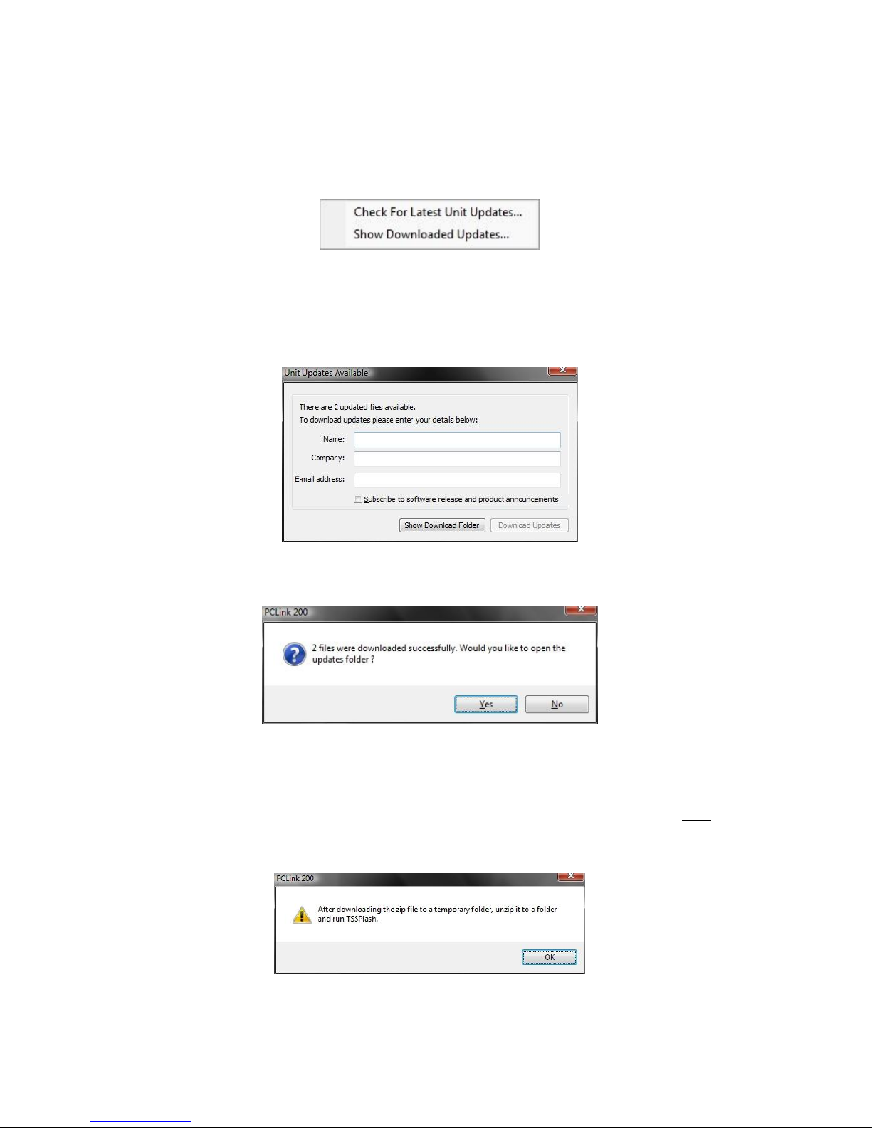
From the Help menu within PCLink, select Updates and choose from the following;
Check for Latest Unit Updates... PCLink will connect to the internet and check for updates for
PCLink, X200 and X300. If this is the being run for the first time, updates will be found and downloaded.
Subsequent checks where no new version are available, the download will be skipped. Some basic
user information will be collected and the option to be included in future software and product
notifications.
Show Downloaded Updates... PCLink will open the local folder that the updates were downloaded
to.
If updates are available for Timespace DVRs, the downloaded .xos files will be stored in the DVR sub
folder e.g. Update\X200\X200 V1.9.0.xos
If a PCLink Suite update is available it will be downloaded as a .zip file using the PCs Internet browser,
giving the user the opportunity to Save the file to their preferred folder. Once complete, the file must be
unzipped to a temporary folder and TSSplash.exe run (double clicked). This will initiate the PCLink
installer.

28
LANGUAGE SELECTION
By default the X300 menu system is displayed in the English language.
Timespace Technology can provide a language template file which the user can translate and return to
Timespace Technology for incorporation into the X300 software. This will allow all text displayed on the
Reviewer to be in the users preferred language.
Language is selected in the SYSTEM SETTINGS > RESET menu. The X300 requires a power cycled
before the new language settings will take effect.
VIDEO STANDARD - PAL / NTSC
The X300 offers the ability to switch between different video standards; PAL and NTSC.
PAL (Phase Alternating Line) is the standard used in most European countries with the exception of
France. The X300, when configured to use PAL, offers a maximum capture rate of 25 fields per
second.
NTSC (National Television Standards Committee) is the standard used in the United States of America.
The X300, when configured to use NTSC, offers a maximum capture rate of 30 fields per second.
When configured to use one of these standards, the X300 must use it exclusively. This means that
cameras of different types cannot be mixed on the device‟s inputs.
Note that if the unit is configured for PAL and an attempt is made to play back NTSC recordings, the
image will appear vertically „squashed‟. Similarly, if the unit is configured for NTSC and an attempt is
made to playback PAL recordings, the image will be clipped.
Switching Video Standards
To switch between the required video standard, the user must configure the unit using the SETTINGS >
SYSTEM SETTINGS > CAMERA OPTIONS > VIDEO SETTINGS menu. Once the selection has been
made the unit must be power cycled before it comes into effect. PAL is the default setting.
FILE SYSTEM
The X300 uses a proprietary file type with the file extension .XBA. Images from multiple cameras along
with audio, GPS and other meta data are stored in these files. The X300 stores XBA files on the
cartridge in a loop over the physical disk and does not use a fragmented file structure. The X300 uses a
linking mechanism (FAT area) for PC compatibility. This compatibility conforms to the Microsoft
standard FAT32 filesystem that is compatible on all PC‟s and many other systems.
Two types of File System behaviour are available on the X300; Loop and Single Pass.
Loop Recording
The X300 will automatically delete the oldest recordings first when the Hard Disk Cartridge is full (with
the exception of write-protected files). Write-protection can be used to keep Alarm recordings but loop
the background (Normal) recording.
Single Pass Recording
The X300 records until the Hard Disk Cartridge is full and then stops.
Recordings may be deleted in the SETTINGS > SYSTEM SETTINGS > RESET menu or loop recording
enabled so that the oldest files will be overwritten first. The File System Recording Mode is set in the
SETTINGS > SYSTEM SETTINGS > FILE SYSTEM menu.

29
VIDEO COMPRESSION
The X300 records images, audio, GPS and other meta data into 5 minute, 10 minute or 1 hour
proprietary format files ending with the .XBA file extension. For security and optimisation reasons .xba
files can only be viewed on a PC using the proprietary PCLink200 software or authorised Timespace
partner software.
The images are compressed using MPEG2 in Full Update mode. In Full Update mode, each image
stands alone in its own right and uses no prediction from previous images. The advantage of full update
recording is that each image is independent and free from any inter-image distortion. The images can
also be searched easily during playback.
A trade-off between image quality and file size can be made by selecting different levels of video quality
on the X300: low, medium, high, v.high, v.v.high and supd1. The low setting uses greater compression
than the higher settings and consequently less disk space is used.
As image quality rises however so does the resultant file size so a decision will have to be made as to
the level of image quality needed and the length of recording required to be stored on any given size of
Hard Disk Cartridge. The X300 uses a variable bit-rate to produce an average image size of xKB – x is
dependent upon the quality setting (see below for images sizes);
SUPD1 50KB per image
VV.High 42KB per image
V.High 34KB per image
High 26KB per image
Medium 18KB per image
Low 10KB per image
The X300 can record in two resolutions;
D1 Frame Resolution 720 x 576 (pixels)
2CIF Frame Resolution 720 x 288 (pixels)
The resolution will automatically change from 720x288 to 720x576 when increasing from the SUPER to
SUPD1 as the image becomes interlaced.
The X300 provides an on-screen calculator during setup when using the Reviewer. It shows how long
the recordings will last before they are overwritten. This is based on the current quality, images per
second settings and the installed cartridge size.
 Loading...