

Timespace X100 Instruction Manual
X100
Digital Video Recorder
and Product Family
Instruction Manual
© 19
th
April 2004 [V1.51m]
Intelligent Security & Fire

X100
Digital Video Recorder
and Product Family
Instruction Manual
CONTENTS
Contents........................................................................................................................................2
System Overview ..........................................................................................................................5
X100 Digital Video Recorder ........................................................................................................6
Installation ..............................................................................................................................7
Mounting Diagram............................................................................................................7
Rear Panel .......................................................................................................................8
Front Panel ......................................................................................................................9
Connector Specifications ............................................................................................... 10
Alarm Connector, Din Connector ............................................................................10
X100 Modem Connector .........................................................................................10
X100 RJ45 (Reviewer) Connector ..........................................................................10
Cable Specifications ......................................................................................................11
X100 RJ45 Reviewer Socket to PC Cable ..............................................................11
X100 Modem Socket to GSM/PSTN Modem Cable ...............................................11
X100 to Reviewer Cable..........................................................................................11
Anti-Vibration Kit (T406) .......................................................................................................12
Programming........................................................................................................................16
Help Screens........................................................................................................................16
Software Updates.................................................................................................................17
X100 & Hard Disk Cartridge LED Indicators ........................................................................18
Operation.............................................................................................................................. 21
Playback & Recording....................................................................................................21
Camera Switcher ...........................................................................................................22
Zoom, Search and Help.................................................................................................23
Jump to Time .................................................................................................................24
File System........................................................................................................................... 25
Loop Recording..............................................................................................................25
Single Pass Recording...................................................................................................25
Example - day long files.................................................................................................26
Example - hour long files ...............................................................................................27
Example - 10 minute files ..............................................................................................28
Write-Protection .............................................................................................................29
Putting footage back onto an X100................................................................................30
JPEG Compression .......................................................................................................31
PC Access Precautions .................................................................................................31
Permitted on a PC ...................................................................................................31
Not Permitted on a PC ............................................................................................31
Permitted with Caution on a PC ..............................................................................31
2
Intelligent Security & Fire

Watermark............................................................................................................................32
Watermark Definition .....................................................................................................32
Accessing Watermark....................................................................................................33
Watermarks and PCLink Split Utility..............................................................................33
Hard Disk Cartridge.............................................................................................................. 33
Thermal Design ....................................................................................................................34
Forced Ventilation Within Enclosures............................................................................34
Low Temperatures.........................................................................................................35
The Menu System...................................................................................................................... 36
Help Screens .................................................................................................................36
Default Settings..............................................................................................................36
Menu Navigation ............................................................................................................37
Main Menu .....................................................................................................................38
Normal Recording Menu................................................................................................39
Recording time, disk size and recording rate..........................................................41
Timer Recording Menu ..................................................................................................42
Timer Menu....................................................................................................................43
Alarm Recording Menu ..................................................................................................44
Recording History (Files) Menu ..................................................................................... 46
File Listing ...............................................................................................................46
Voluntary Write-Protection ......................................................................................46
Jump to File.............................................................................................................46
Alarm Input Menu...........................................................................................................47
Alarm Output Menu........................................................................................................48
Video Switcher Menu.....................................................................................................49
Other Menus ..................................................................................................................50
Password Menu .............................................................................................................51
Hints ........................................................................................................................51
Examples.................................................................................................................52
Monitor Menu .................................................................................................................53
Camera Text ..................................................................................................................54
Current Date Menu ........................................................................................................55
Statistics Menu...............................................................................................................56
Advanced Menu .............................................................................................................57
Low Power Standby Mode ......................................................................................57
File System Menu ..........................................................................................................60
Check Files Menu ..........................................................................................................62
Reset System Menu.......................................................................................................63
SMS Message Menu......................................................................................................64
Sending emails via a gateway.................................................................................66
X101 Reviewer............................................................................................................................67
Mounting Diagram ................................................................................................................68
Operation.............................................................................................................................. 69
Camera Tester......................................................................................................................69
Using the X201 Reviewer with the X100..............................................................................70
Accessing / Storing Images ........................................................................................................72
PCLink V2.21........................................................................................................................72
Introduction ....................................................................................................................72
V2.21 enhancements over V2.1 ....................................................................................72
Minimum Requirements.................................................................................................72
Installation......................................................................................................................73
Starting PCLink ..............................................................................................................73
Installing Cartridge.........................................................................................................73
PCLink v2.21 Quick Reference......................................................................................74
Operating PCLink...........................................................................................................75
Camera Buttons ......................................................................................................75
Camera Display Mode Buttons................................................................................76
3
Intelligent Security & Fire

Camera Windows ....................................................................................................76
Zoom .......................................................................................................................76
Play Controls ........................................................................................................... 76
Timeline Selectors...................................................................................................77
Timeline Marker Flags............................................................................................. 77
Video Information Panel..........................................................................................78
Speed Control .........................................................................................................78
Watermarks ............................................................................................................. 78
Password.................................................................................................................79
File Transfer...................................................................................................................79
Pasting Image to Art Package .......................................................................................80
RemoteLink V1.1.2...............................................................................................................81
Introduction ....................................................................................................................81
Overview ........................................................................................................................81
Hardware Required........................................................................................................ 82
Specification of Cabling .................................................................................................82
RJ12 Power Cable ..................................................................................................82
RS232 Serial Cable.................................................................................................82
Installation......................................................................................................................83
1 Configure the SIM card .......................................................................................83
2 Insert SIM card into modem ................................................................................84
3 Load V1.5 software onto X100 system ...............................................................84
4 Connect modem equipment ................................................................................84
5 Install Remote Link V1.1.2 onto PC ....................................................................84
Running RemoteLink .....................................................................................................85
Selecting a modem ........................................................................................................ 86
Entering / managing phone numbers.............................................................................87
Contacting a remote unit................................................................................................88
Remote operation ..........................................................................................................89
Removing RemoteLink...................................................................................................89
OBA to AVI File Converter V1.1.2 ........................................................................................90
Introduction ....................................................................................................................90
Usage.............................................................................................................................90
Transferring Files to PC .......................................................................................................92
USB Interface Kit (T403-USB) .......................................................................................92
FRAME Interface Kit (T403-FRM) .................................................................................92
Transferring Images to Video Tape......................................................................................92
Appendix .....................................................................................................................................93
Safety ...................................................................................................................................93
X100 EMC Conformity (CE Mark) ........................................................................................ 93
X100 EMC Conformity (E Mark)...........................................................................................93
X100 EMC Conformity (Specification 5)...............................................................................94
Guarantee.............................................................................................................................94
Specifications .......................................................................................................................95
X100 Digital Video Recorder .........................................................................................95
Removable Hard Disk Cartridge....................................................................................96
X101 Reviewer...............................................................................................................96
Troubleshooting....................................................................................................................97
Error Messages and Other Messages...........................................................................97
Possible Problems and FAQ's .....................................................................................100
X100 ......................................................................................................................100
X101 ......................................................................................................................100
T406 ......................................................................................................................101
4
Intelligent Security & Fire

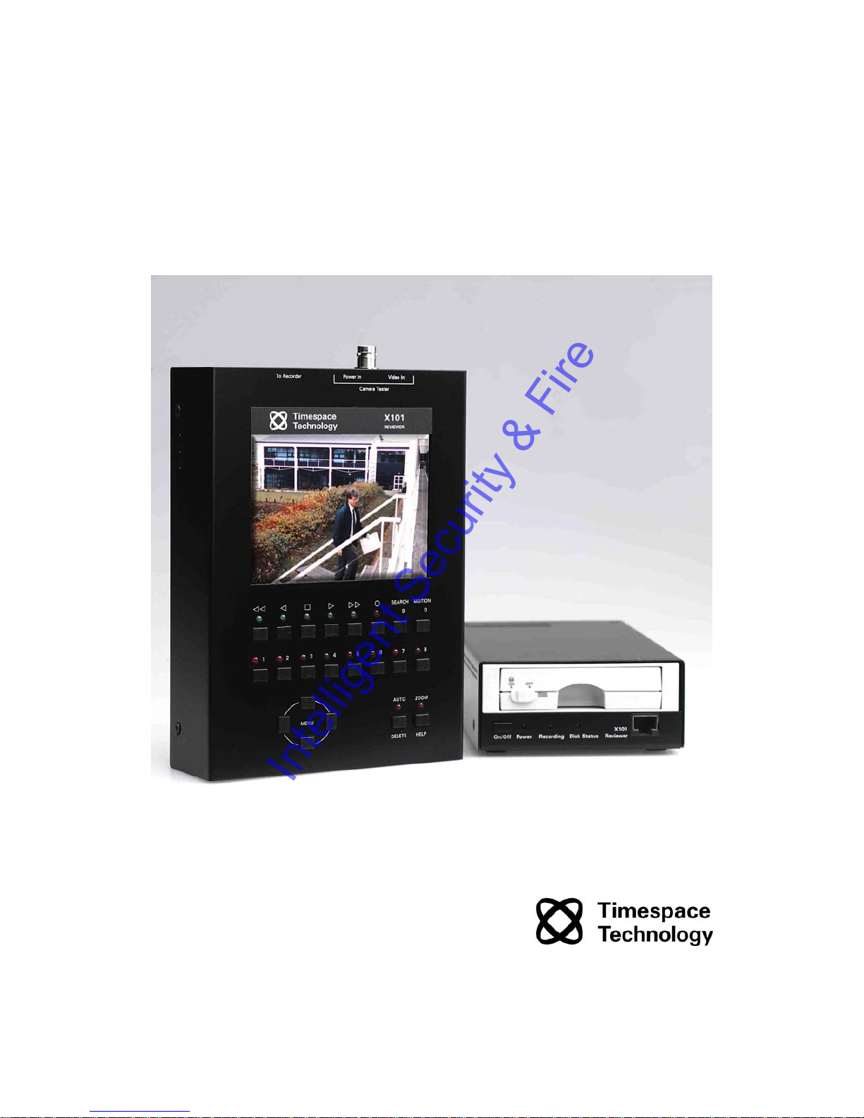
SYSTEM OVERVIEW
The X100 is a digital video surveillance recorder for use in covert, portable and mobile
applications.
Recordings are made on a removable hard disk cartridge inserted in the X100. After the hard
disk cartridge has been removed, the recordings can be accessed by connecting the cartridge
to a PC, using either USB or Frame Interface Kits, which includes PCLink, a proprietary reading
and archiving software package.
The X101 Reviewer is used to program the menu settings on X100, to check camera views and
to review recordings on the installed X100 hard disk cartridge. Recording will continue during
this reviewing process.
The X100 and X101 are available in either PAL or NTSC models.
The 24-hour clock is used for all times and settings.
WARNING: The X100 Recorder must always be mounted so that there is a free flow of air
around it. If it is mounted in an enclosure, it is essential that adequate ventilation is
provided, and it is recommended that a fan is incorporated in the enclosure design.
WARNING: If the X100 Recorder is mounted in a vehicle, or otherwise subject to
vibration, suitable damping must be built into the mounting.
WARNING: Hard disk cartridges are sensitive to shock, vibration and humidity.
5
Intelligent Security & Fire

X100 DIGITAL VIDEO RECORDER
6
Intelligent Security & Fire
Installation
The X100 can be used free-standing or it can be mounted on a wall or bulkhead.
Power can be applied to X100 either via 12V DC jack socket (use PSU supplied with X100), or
12V screw terminals. NB: Do not use both power inputs simultaneously.
The Hard Disk Cartridge (supplied separately) with lock on the front in "Off" position should be
inserted into receptacle in front panel of X100 and gently but firmly pushed into place, then lock
switched to "On" position.
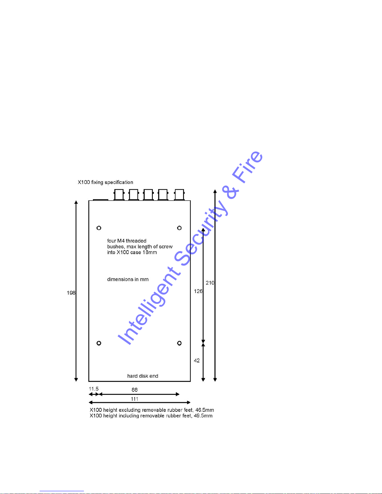
Mounting Diagram
4 x threaded holes are available in the back panel of the X100 for mounting:
7
Intelligent Security & Fire

Rear Panel
Video Out For connection to external monitor
Video In (BNC) Connect cameras 1 to 4 to these sockets
Video In (DIN) Connect cameras 5-8, using 5 pin 180° DIN locking plug
(Deltron part 590-0500; Farnell order code 590-0500).
DC Power Socket For PSU supplied only (use DC power terminals where possible)
DC Power terminals 1 x pair screw terminals to be used in preference to Socket
Alarm Inputs 4 x pair screw terminals (cameras 1 to 4 only)
Alarm Output 1 x pair screw terminals
Modem For connection to GSM modem
8
Intelligent Security & Fire
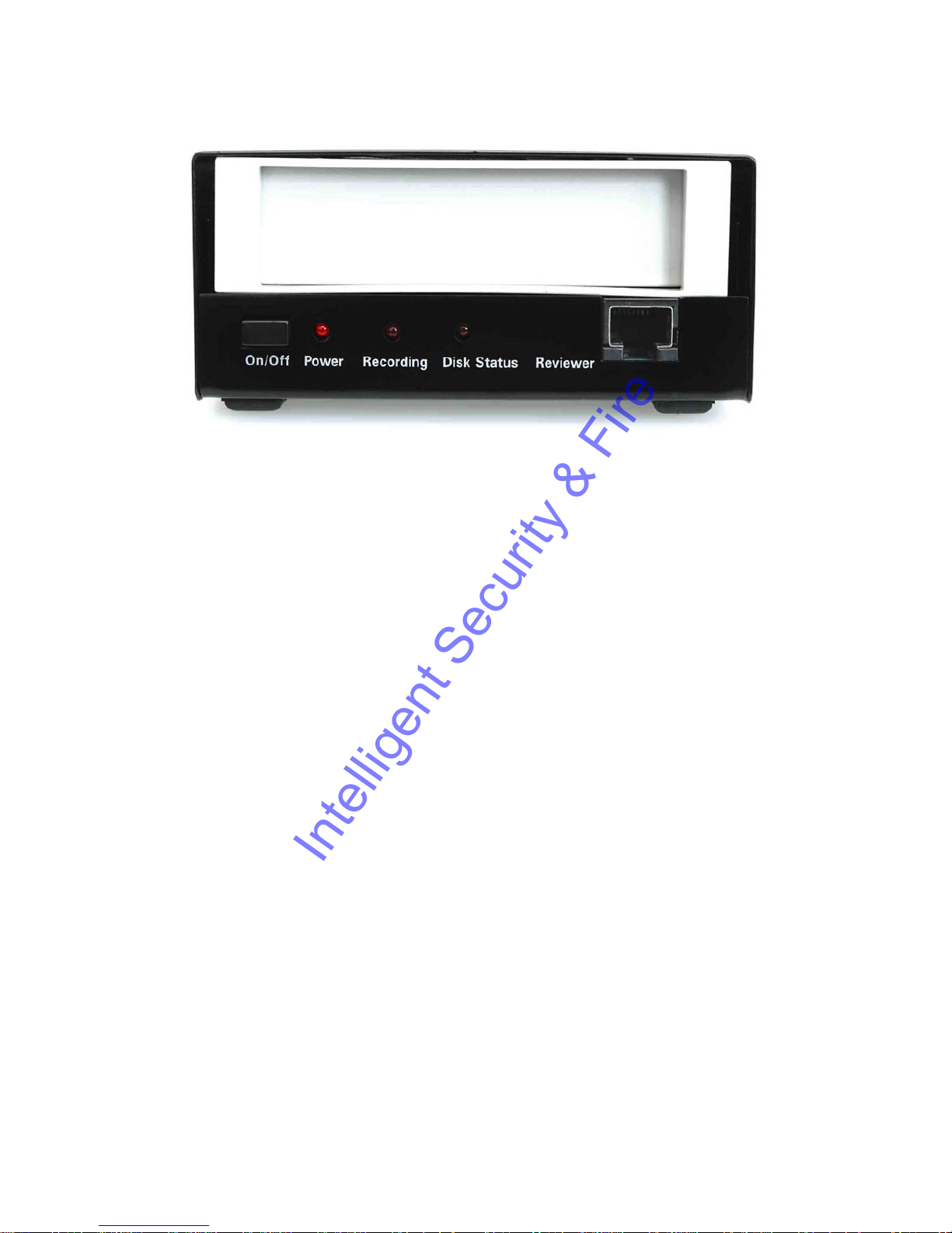
Front Panel
Main Bay Insertion of hard disk cartridge
On/Off Power to X100 (menu enabled)
Power LED Flashing in low power standby mode,
On all the time for normal operation
Recording LED On when recording
Disk Status LED On when disk full (applies to single pass recording only)
Reviewer Connection to X101 Reviewer (power, video and keypad control)
9
Intelligent Security & Fire
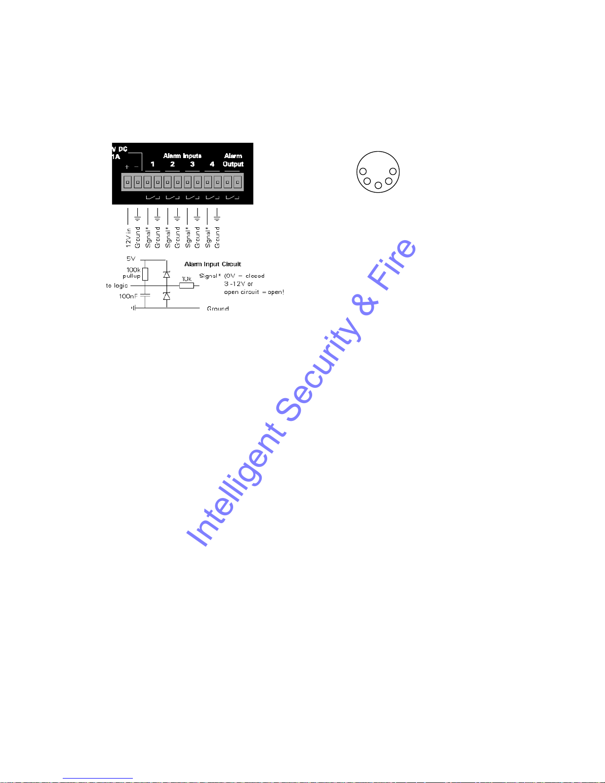
Connector Specifications
Alarm Connector, Din Connector
76
8
5
GND
DIN SOCKET
CONNECTIONS
(looking at rear panel)
Video inputs 5 to 8
X100 Modem Connector
Arranged as per IBM PC 9 pin serial port. The connector is a 9 way D-Type female connector.
IN/OUT
1 DCD IN
2 RD IN
3 TD OUT
4 DTR OUT
5 GND
6 DSR IN
7 RTS OUT
8 CTS IN
9 RI not connected within X100
X100 RJ45 (Reviewer) Connector
The pin configuration of the RJ45 connector is proprietary. It must not be connected to an
Ethernet network.
Pin 1 is the pin closest to the centre of the X100 front panel.
1 Video Out Use 1 and 2 for Video Out
2 GND
3 GND
4 RD IN (serial connection RS232)
5 TD OUT (serial connection RS232)
6 Reviewer detect, pulled up to 5V internally. Connect to GND for Reviewer
7 GND 3 and 7 power / RS232 ground
8 +12V DC output This is directly connected to the +12VDC input on the X100
10
Intelligent Security & Fire

Cable Specifications
X100 RJ45 Reviewer Socket to PC Cable
This cable is used to connect a PC to the X100 RJ45 (Reviewer) socket.
9 way D-Type female connector to RJ45 plug.
[Typically use a standard CAT5 cable [EIA/TIA 568B wiring standard (straight 1-8 to 1-8
connection)] and cut and wire onto the D type connector]
Connect pins as follows:
RJ45 Cable Modem Plug
1 White with orange stripe
2 Orange (with white stripe)
3 White with green stripe Pin 5
4 Blue (with white stripe) Pin 3
5 White with blue stripe Pin 2
6 Green (with white stripe)
7 White with brown stripe Pin 5
8 Brown (with white stripe)
Cable wires 1, 2, 6 and 8 can be cut back (not connected)
X100 Modem Socket to GSM/PSTN Modem Cable
9 way D-Type female to 9 way D-Type male connectors.
Connect all pins straight through
1-1
2-2
3-3
4-4
5-5
6-6
7-7
8-8
9-9
X100 to Reviewer Cable
Standard CAT5 cable (shielded) [EIA/TIA 568B wiring standard (straight 1-8 to 1-8 connection)]
11
Intelligent Security & Fire
Anti-Vibration Kit (T406)
Please adhere to the following instructions for the installation of the Anti-Vibration Kit. Failure
to do so may result in the Mounting System not working correctly.
Section A – Inventory Of Parts
The Anti-Vibration Kit consists of the following parts -
QTY Description
4 Wire Rope Mounts
1 Stabiliser Coupling
8 Zinc Plated M4 x 10mm Counter-Sunk Hex-Head Screws.
In addition you will require a standard ‘L’ shaped hex key. This is essential, as when all of the
other screws have been tightened, there is no room for any other tool to tighten the front lower
pair of screws.
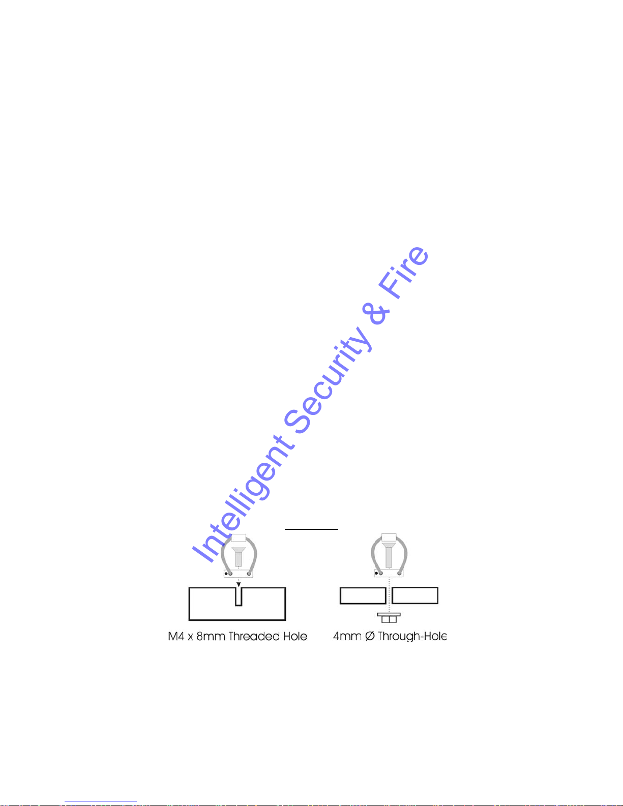
Section B - Mounting Surface/Enclosure Preparation
Mounting Hole Preparation
Drill four mounting holes to attach the Wire Rope Mounts. If you intend to use the M4 x 10mm
screws into blind holes, then the holes will have to be drilled and tapped to accept an M4
screw, with a thread depth of no less than 8mm.
If mounting the Wire Rope Mounts through a metal plate, then longer screws may have to be
used in order to allow a washer and nut to be attached on the other side of the plate. The
length of these screws will have to be chosen depending on the thickness of the plate and the
height of the washer and nut.
Please note that any screw used for mounting the wire rope mounts to an enclosure surface
must have an M4 thread and have a counter-sunk hex-head.
Please refer to Diagram B1 for details of blind and through-hole mounting.
Diagram B1
Mounting Hole Location – X100
The mounting holes must be drilled on 126mm and 88mm centres. This is shown in diagram
B2.
12
Intelligent Security & Fire

Diagram B2
Total Mounting Volume Required – X100
It is necessary to allow a minimum clearance of at least 10mm around the body of the X100
when mounted on the T406 Anti Vibration Kit. This is to allow free movement of the X100 on
the anti vibration mounts and to prevent collision with either the enclosure or peripheral
systems due to vertical and lateral movement under extreme shock and vibration conditions.
Please refer to diagram B3 for exact dimensions.
Diagram B3
Please note that when installing cables to the rear of the X100 it is important not to
arrange or clamp them in such a way as to impede the free movement of the rear antivibration mounts. Please refer to diagram B4 on the following page.
13
Intelligent Security & Fire

Diagram B4
Section C - Installation Procedure
It is advised that some form of thread-lock compound should be used on the screws
securing the wire rope mounts to both the X100 and mounting surface. This is in order
to prevent loosening due to vibration.
1) Attach the Wire Rope Mounts to the X100 with four of the countersunk M4 hexhead screws provided and L-shaped hex key. When attaching the rear pair of
mounts please ensure that the stabilizer is ‘sandwiched’ between the mounts and
the X100 by aligning the stabilizer holes with the mounting holes in the X100.
Please refer to diagram C1.
Please note that the ‘open’ end of the C-shaped plastic stabiliser should be attached to
the rear wire rope mounts and face backward as shown in diagram C1.
2) Once all of the Wire Rope Mounts have been securely attached to the X100, use a
pair of countersunk M4 hex-head screws to attach the bottom ‘feet’ of the front
Wire Rope Mounts to the mounting surface/enclosure.
3) Secure the lower ‘feet’ of the rear Wire Rope Mounts to the mounting
surface/enclosure using the remaining pair of countersunk M4 hex-head screws
and a standard L-shaped hex key. Ensure that the stabilizer is ‘sandwiched’
between the lower feet and the mounting surface/enclosure by screwing through
the Wire Rope Mount feet, then the stabilizer and into the mounting
surface/enclosure.
Diagram C1
14
Intelligent Security & Fire
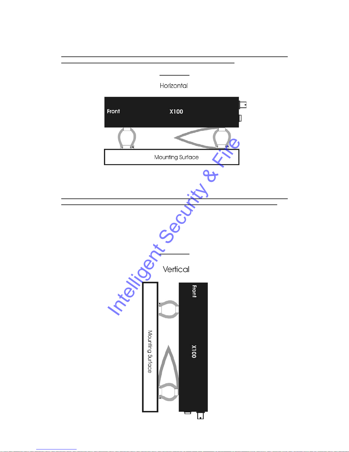
Orientation of Unit
The X100 should be mounted in the following horizontal orientation as per diagram C2.
This is strongly advised for maximum vibration and shock isolation.
Diagram C2
If it is not possible to mount the X100 in the horizontal orientation then the following vertical
orientation as detailed in diagram C3 may be used.
It must be noted however that this vertical orientation is not as effective at isolating the
X100 from vibration and shock as the horizontal orientation as shown in diagram C2.
The position of the plastic stabiliser, screw types and assembly order remain the same for this
mounting orientation.
The X100 must never be mounted by hanging it upside down from a horizontal surface when
using this mounting system.
Diagram C3
15
Intelligent Security & Fire

Programming
The configuration of the X100 is by the menu system.
Connect Data Link Cable (supplied with X101 Reviewer) from socket marked "Reviewer" on
X100 to socket marked "To Recorder" on X101. This connection will provide power and video
to X101 from X100.
WARNING: When X101 is connected to X100 the power supplied to X100 must be 12V+/-
1.2V. An additional PSU can be connected to "Power In" socket of X101, but to view
X100 a BNC cable must be linked from "Out" socket on rear panel of X100 to "Video In"
socket on top panel of X101.
To enter Menu System press menu key.
Help Screens
Throughout the menu system, every item that the cursor points to has a Help screen. Place the
cursor on the line requiring explanation and press "Help" key on X100 front panel. Use any
key to cycle through the screens for that line. No Help screen is available for Statistics Menu.
16
Intelligent Security & Fire

Software Updates
Occasionally software improvements are made to X100 and a new version of software is made
available. Follow these steps to download new software:
Ensure X101 Reviewer is not connected to X100 Recorder.
Connect serial link cable from "Reviewer" socket on X100 front panel to serial port on PC.
With hard disk cartridge inserted and switched on, hold in "On/Off" button on front panel of
X100 then connect power to X100. Release On/Off button. All three LED's on X100 front panel
should now be illuminated. Alternately, maintain power to X100, and switch off hard disk
cartridge. Hold X100 On/Off button in and switch on hard disk cartridge.
When all three LED's on X100 front panel illuminated, the Recorder is ready for download.
NB: Full reset will delete all existing recordings on hard disk.
Wait 40 seconds after download until LED on hard disk cartridge changes from amber to green.
17
Intelligent Security & Fire

X100 & Hard Disk Cartridge LED Indicators
The following section describes the normal operation of the front panel LED indicators on the
X100 and hard disk cartridge. It may be useful in order to confirm normal operating conditions
and situations where a problem may have occurred.
X100 With Hard Disk Cartridge Inserted
1) When an external 12V DC power supply is connected to the X100.
i) The ‘Power’ LED will illuminate to indicate that 12V DC power is being supplied to the
X100 via either of the rear panel inputs. The ‘Power’ LED will remain illuminated until
the power supply is removed or the unit is placed into low power standby mode as
detailed in section 4 following.
If the ‘Power’ LED is dim and/or the hard disk cartridge does not follow the sequence as in
section 2 following, then there may be insufficient voltage to supply the X100.
Please note that the X100 and hard disk cartridge require a 12V +/-1.2V DC power supply.
2) When a hard disk cartridge is inserted and switched on.
i) The hard disk cartridge LED will illuminate green and flash amber intermittently as
operating code is loaded into X100.
ii) The ‘Recording’ & ‘Disk Status’ LED’s will illuminate simultaneously for approximately 1
second and then switch off.
3) Whilst recording.
i) The ‘Recording’ LED will illuminate and remain lit for the duration of the recording.
ii) The hard disk cartridge LED will remain illuminated in green but will intermittently flash
amber as data is recorded to the hard disk. The frequency of the amber flashes will
depend on the chosen recoding parameters.
18
Intelligent Security & Fire

4) When the unit is placed in low power standby mode.
In the default setting the X100 is placed into low power standby mode by pressing the front
panel ‘On/Off’ button whilst the unit is in normal operating mode.
This feature may be software configured by accessing the menu system via the X101 reviewer.
To change the low power standby mode setting, go to ► Other Menus ►Advanced, and use
the ‘Pushbutton Switches’ option. The various options are detailed in the ‘Low Power Standby
Mode’ section of the manual.
i) The ‘Power’ LED will flash intermittently.
ii) The hard disk cartridge LED will switch off.
iii) The ‘Recording’ LED will switch off and recording will cease if the X100 is placed into
low power standby mode whilst recording.
Please note that the X100 will switch back to normal operation from low power standby mode if
the front panel ‘On/Off’ switch is pressed, the X101 reviewer is attached or the state of an alarm
input changes.
Low power standby mode is not accessible unless a hard disk cartridge is inserted and
switched on.
5) If the ‘Disk Status’ LED is illuminated.
The ‘Disk Status’ LED indicates one of the following conditions.
i) The hard disk cartridge is full of write-protected files.
In this situation an attached X101 will show the current camera output determined by the video
switcher, and the menu system will be accessible as per normal.
The hard disk cartridge will be full due to the options in the X100 ‘File System’ menu having
been set to write-protect certain types of recordings (any combination of Normal, Timer &
Alarm). The X100 will not re-record (Loop recording) over write-protected recordings and will
therefore not make any new recordings once the disk is full of write-protected recordings
(Single pass recording).
In order to change the write-protection settings, access the X100 menu with the X101 reviewer
and go to ► Other Menus ► File System. At the top of the ‘File System’ menu is ‘Write
Protection For’. Write-protection can then be enabled or disabled for each type of recording as
required.
Please refer to the ‘File System’ section in the manual for more details on which settings to use.
Please note that in its default setting the X100 automatically write-protects Alarm recordings but
not Normal or Timed recordings.
ii) If it has been established that the hard disk cartridge is not full of write-protected files.
In this case the illumination of the ‘Disk Status’ LED may indicate that the operating code was
not loaded from the hard disk cartridge to the X100 correctly when the external 12V DC power
supply was last connected and the hard disk cartridge switched on.
In this situation an attached X101 will show ‘snow’ on the screen and the menu system will not
be accessible.
In order to reset the system and reload the operating code, either switch the cartridge to the off
position and wait at least 5 seconds before switching back on or disconnect the external power
supply from the X100 and wait at least 5 seconds before reconnecting.
19
Intelligent Security & Fire

If the ‘Disk Status’ LED remains illuminated after reset, then the operating code on the hard
disk cartridge may be corrupted, there may be corrupted recording files on the disk or the hard
disk itself may be damaged.
If the ‘Disk Status’ LED remains illuminated after resetting the system as described previously,
then please contact the equipment supplier.
6) If the ‘Recording’ & ‘Disk Status’ LED’s flash twice, instead of once, when the hard
disk cartridge is switched on.
If this occurs instead of the usual sequence as described in section 2 previously, then the X100
has entered a mode reserved for Timespace Technology engineers to adjust factory settings.
To exit this mode, either switch the cartridge to the off position and wait at least 5 seconds
before switching back on or disconnect the external power supply from the X100 and wait at
least 5 seconds before reconnecting. If the same situation reoccurs after the external 12V DC
power supply has been reconnected, then please contact the equipment supplier.
7) If the ‘Recording’ & ‘Disk Status’ LED’s remain illuminated when the hard disk
cartridge is switched on.
If this occurs it indicates that the hard disk cartridge is ready to download new operating
software. Please refer to the ‘Software Updates’ section in the manual for the correct
procedure for downloading software to a hard disk cartridge.
If this state has been triggered accidentally, either switch the cartridge to the off position and
wait at least 5 seconds before switching back on or disconnect the external power supply from
the X100 and wait at least 5 seconds before reconnecting. This will re-start the X100 and hard
disk cartridge in normal operating mode.
20
Intelligent Security & Fire

Operation
To set up and operate the X100 an X101 Reviewer is required.
Playback & Recording
Rewind through recorded footage. The normal wind interval is 1 minute. Pressing the
button again increases the wind interval to 5 minutes. Repeated presses increase the
interval to 10 / 20 and finally 60 minutes. This rapid scan mode enables fast, flickerfree searching through recorded material. If the LED above the stop button is lit the
unit is in jog mode and the rewind button will rewind through recorded footage frame by
frame, with intervals of 1 minute.
Reverse-play through recordings. If the LED above the stop button is lit (jog mode),
the reverse-play button will jog to the previous frame. If the oldest frame has been
reached, reverse playback will stop. Note that reverse play only operates on images
that have been first played in a forward direction.
Stop playback. If playback is already stopped, pressing this button again lights the LED
above and the unit is in jog mode, allowing frame-by-frame playback.
Play recorded footage. Pressing play for a second time switches to fast play enabling
all the footage to be played through at the fastest rate. If the LED above the stop button
is lit, the play button will jog to the next frame. If the most recent frame has been
reached, playback will stop.
Fast-forward through recorded footage. If the LED above the stop button is lit the unit
is in jog mode and pressing the fast-forward button will jog forward. Similarly to rewind,
repeated presses of the fast forward enable rapid scan in 5 / 10 / 20 / 60 minute
intervals.
Record start or stop. If not currently recording (red LED off), pressing this button will
begin recording from the end of the most recent footage, using the settings specified in
the Normal Recording menu (see page ). If the unit is currently recording (red LED on),
this button will stop recording.
21
Intelligent Security & Fire
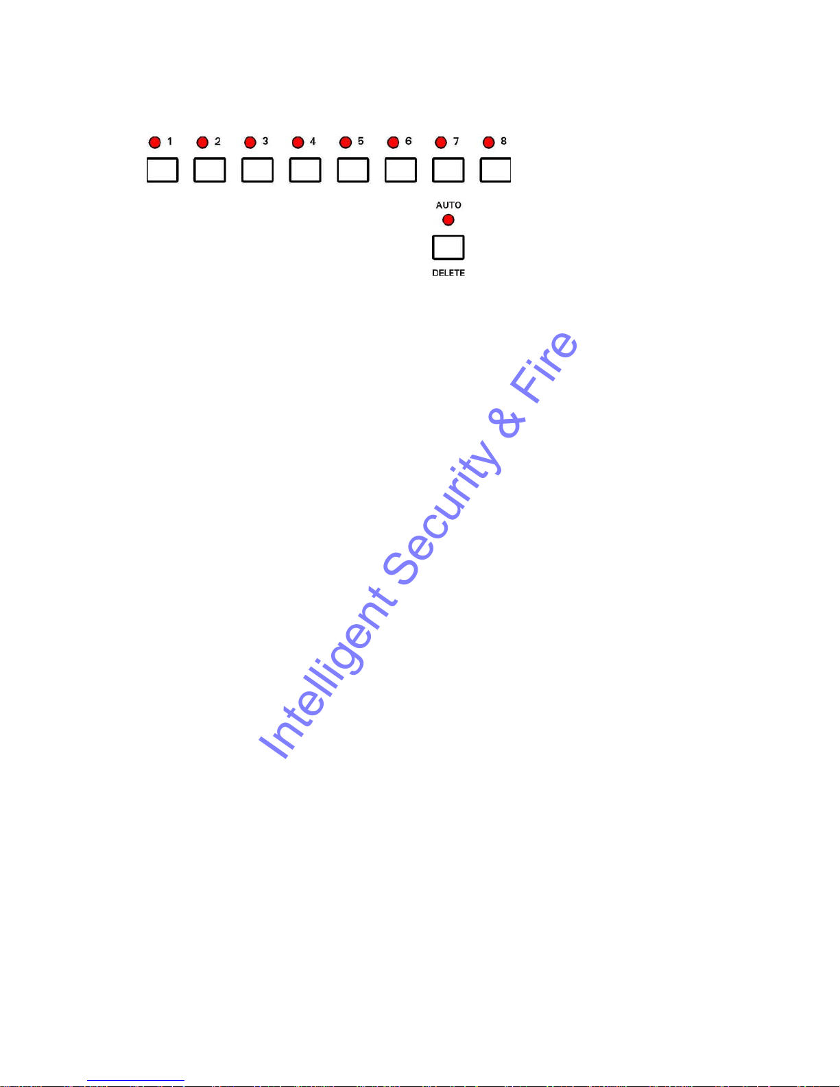
Camera Switcher
1-8 Switch the view to camera 1 to 8. When playing back recorded footage, pressing
buttons 1 to 8 changes playback to that camera. If the AUTO LED is lit, buttons 1
to 8 change the live camera being viewed. This camera is held on the main
monitor.
AUTO Activate the auto switcher mode. In this mode, the monitor will show a live view
and the cameras are cycled as specified in the "Video Switcher" menu. Press the
AUTO button again to deactivate the auto switcher mode. If any of the buttons
numbered 1-8 are pressed while in auto switcher mode, the camera switching is
stopped, and the selected camera view is held on screen.
DELETE When using menus this button is used to delete numbers.
Control of the auto switcher does not affect any recording in progress.
22
Intelligent Security & Fire

Zoom, Search and Help
ZOOM Zoom in on a frame from recorded footage (in black & white). Use the menu
navigation buttons (see next page) to pan around the enlarged image. Press the
ZOOM button again to return to original size. When the zoom function is active,
the ZOOM button will be lit.
HELP Applies when using any menu. Pressing this button will produce a help screen.
Continue pressing any key to cycle through help screens until menu returns.
SEARCH Go to a specific time and date in the recorded footage. Pressing this button will
enter the "Jump to Time" screen. If the footage on a given camera cannot be
found (it may not have been recorded), a "NO CURRENT IMAGES ON CAMERA"
message will be displayed. If there is no footage at the time specified a jump is
made to the nearest footage to the time given.
See the next page for further information on Jump to Time.
MOTION This key is reserved for future use.
23
Intelligent Security & Fire

Jump to Time
JUMP TO TIME
------------
TIME: >14:45:00
DATE: >17/08/98
>JUMP TO TIME ABOVE
>JUMP TO OLDEST
>JUMP TO LATEST
EXIT
This is the "Jump to Time" menu, which is displayed after pressing the SEARCH button, and
allows instant access to any time (on the minute) and date in recorded footage.
• TIME - Type a time using the numbered buttons.
• DATE - Type a date using the numbered buttons.
• JUMP TO TIME ABOVE - Hit the right arrow menu key to jump to the time entered in the
time and date fields.
• JUMP TO OLDEST - Jumps to the oldest recordings on disk.
• JUMP TO LATEST - Jumps to the newest recordings on disk.
If the footage cannot be found for a particular camera (the camera may not have been
recording at that time / date), a NO CURRENT IMAGES ON CAMERA "n" message will be
displayed ("n" being the selected camera view).
If there are no recordings available at a current time specified the JUMP TO TIME function will
jump to the nearest available footage. A jump can only be made to a full image and the JUMP
TO TIME function will jump to the nearest available full image (key frame).
You must use leading zeros for the time and date where necessary, e.g. 09:45 and 04/07/98.
24
Intelligent Security & Fire

File System
Any disk removed from the X100 recorder can be viewed on a PC and recording files
(proprietary format .oba files) are displayed. The disk can be connected to the PC using two
interfacing methods:
Interface Details Product code
1 IDE/USB Easy connection; 12Mbit/sec transfer T403-USB
rate is adequate for PCLink playback
2 IDE (ATA) Disk is inserted into PC T403-FRM
fastest data rate, but technical PC knowledge
required to install frame.
Once the disk has been connected, the disk shows up as a drive letter (typically D:) on the PC.
Recording files can be viewed using Windows Explorer and three examples are given on the
next pages.
Loop Recording
By selecting no write-protection on the recorder:
FILE SYSTEM
-----------
WRITE PROTECTION FOR:
NORMAL RECORDING: >NO
TIMER RECORDING: NO
ALARM RECORDING: NO
it automatically loops deleting oldest recordings first. The record position is stored and any play
back will not affect the current record position (this is in contrast to a VHS tape).
Single Pass Recording
By selecting full write-protection on the recorder:
FILE SYSTEM
-----------
WRITE PROTECTION FOR:
NORMAL RECORDING: >YES
TIMER RECORDING: YES
ALARM RECORDING: YES
it records until it is full and then stops. The disk status LED is lit when it is full. Files may be
un write-protected to free up space or else the recordings may be deleted in the RESET menu.
Write-protection can be used to keep Alarm recordings but loop the background (Normal)
recording.
25
Intelligent Security & Fire
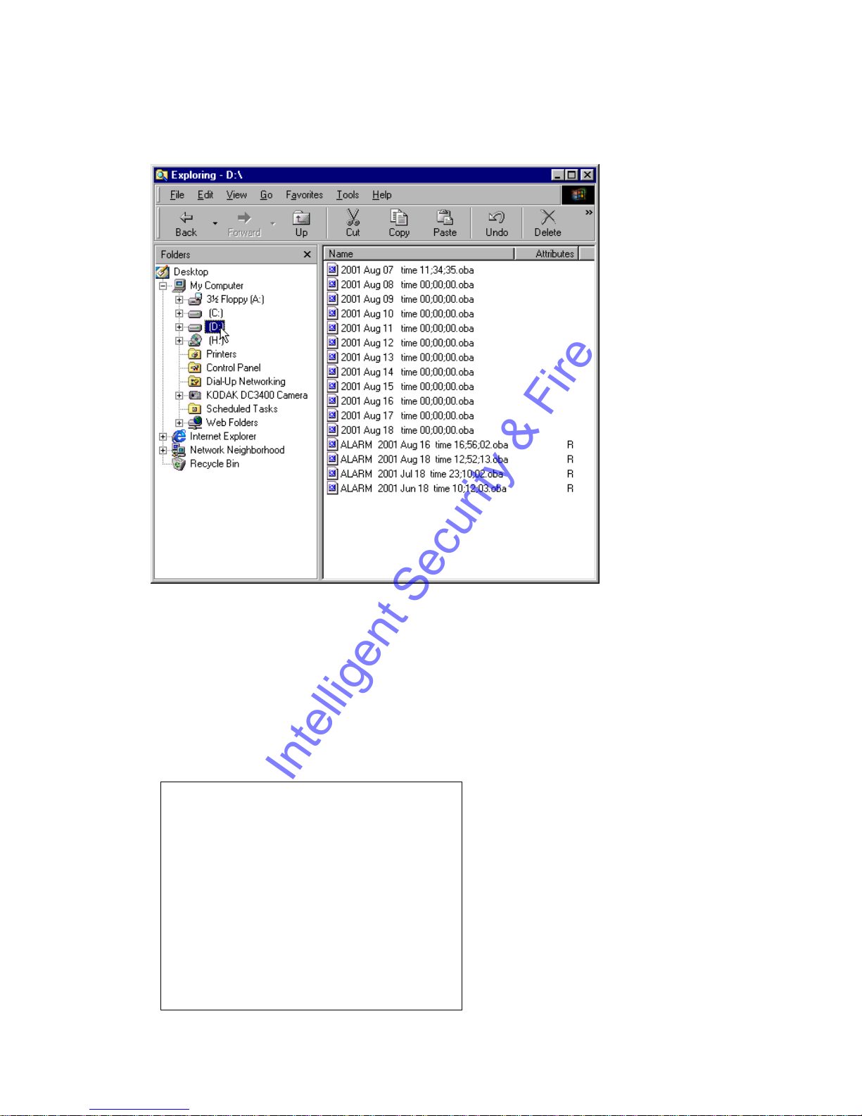
Example - day long files
In the above example the contents of the X100 hard disk cartridge are displayed (D:). 12 files
have been recorded one for each day from 7
th
Aug to 18th Aug. Before this recording period and
within this recording period 4 alarm events were generated and these are stored in event files
"ALARM …. .oba" . Alarm events have been automatically write-protected (R character
meaning READ ONLY) and will never get overwritten by the recorder. The other non writeprotected files are overwritten oldest first in a looping manner automatically by the recorder.
The FILESYSTEM menu on the X100 (OTHER MENUS -> FILE SYSTEM MENU) controls the
way the files are written to the hard disk. Please see the Menu System chapter for more
details. The above disk was generated using the following menu settings:
FILE SYSTEM
-----------
WRITE PROTECTION FOR:
NORMAL RECORDING: >NO
TIMER RECORDING: NO
ALARM RECORDING: YES
FILE LENGTH FOR:
NORMAL / TIMER
RECORDING: 1 DAY
ALARM RECORDING: EVENT
26
Intelligent Security & Fire
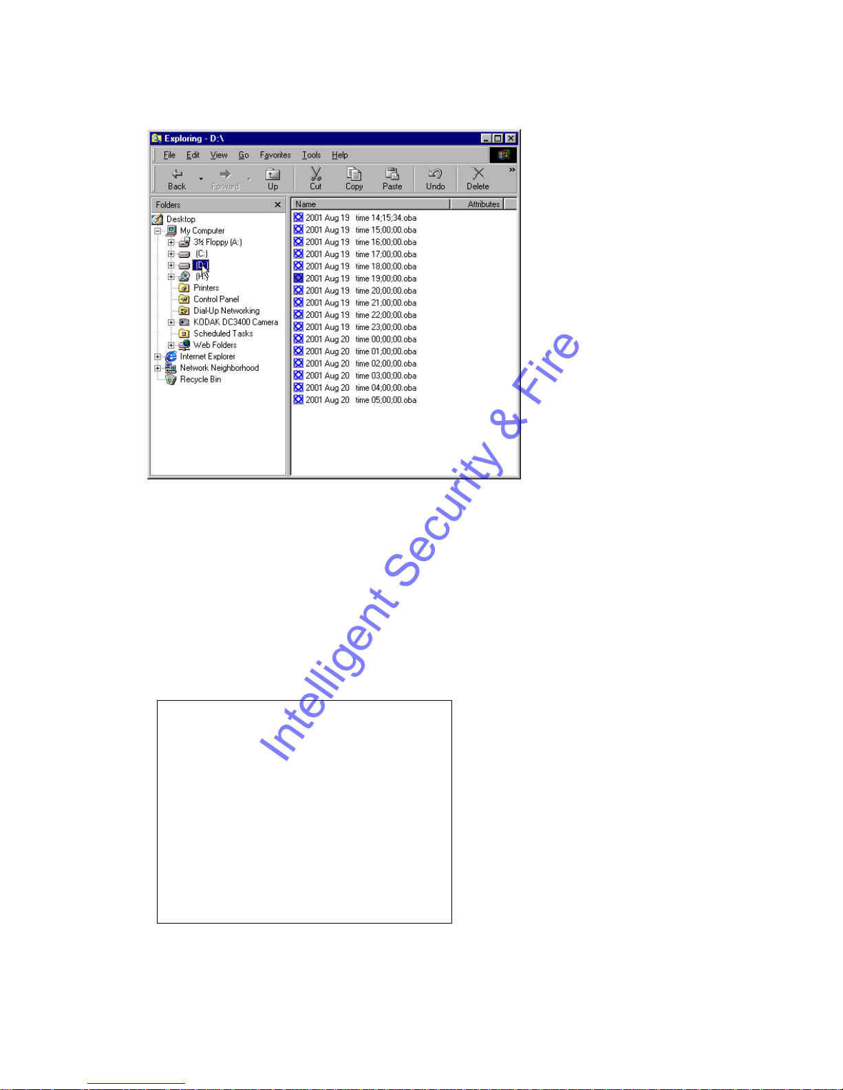
Example - hour long files
In the above example the contents of the X100 hard disk cartridge are displayed (D:). 16 files
have been recorded one for each hour. Recording started at 14:15:34 on August 19
th
and
carried on till 05:06:23 on August 20
th
. The time shown indicates the start time of the file
(ignoring the seconds). If the user stopped recording during any hour and then started
recording again in that hour, the information would be included in the single hour file. 4 alarms
were also triggered over the recording period but the alarm recording has automatically been
included in the hour files (file length for alarm recording was not set to EVENT but to the same
setting as Normal / Timer recording, in this case 1 HOUR)
This example indicates how alarm triggered recordings can be grouped together into hour long
files. Alarm recordings can be grouped together into 10 minute files or day long files as
selected in the File System menu. The following menu settings were used on the recorder:
FILE SYSTEM
-----------
WRITE PROTECTION FOR:
NORMAL RECORDING: >NO
TIMER RECORDING: NO
ALARM RECORDING: NO
FILE LENGTH FOR:
NORMAL / TIMER
RECORDING: 1 HOUR
ALARM RECORDING: 1 HOUR
27
Intelligent Security & Fire
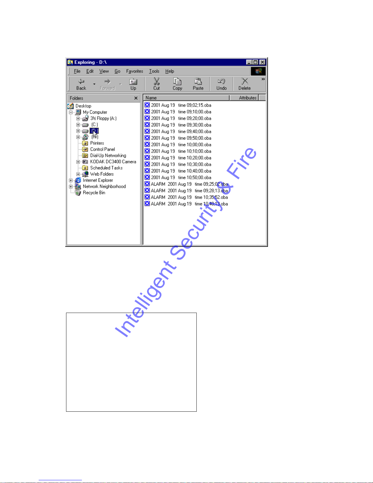
Example - 10 minute files
In the above example the contents of the X100 hard disk cartridge are displayed (D:). 12 files
have been recorded covering a period from 9:02:15am to 10:55:12am. Within this recording
period 4 alarm events were generated and these are stored in the event files "ALARM ….
.oba" . No write-protection has been selected for the alarm recording or normal recording so
the oldest files will be overwritten first.
The following menu settings were used on the recorder:
FILE SYSTEM
-----------
WRITE PROTECTION FOR:
NORMAL RECORDING: >NO
TIMER RECORDING: NO
ALARM RECORDING: NO
FILE LENGTH FOR:
NORMAL / TIMER
RECORDING: 10 MINS
ALARM RECORDING: EVENT
Please refer to the Menu System chapter for further information of the above menu.
28
Intelligent Security & Fire
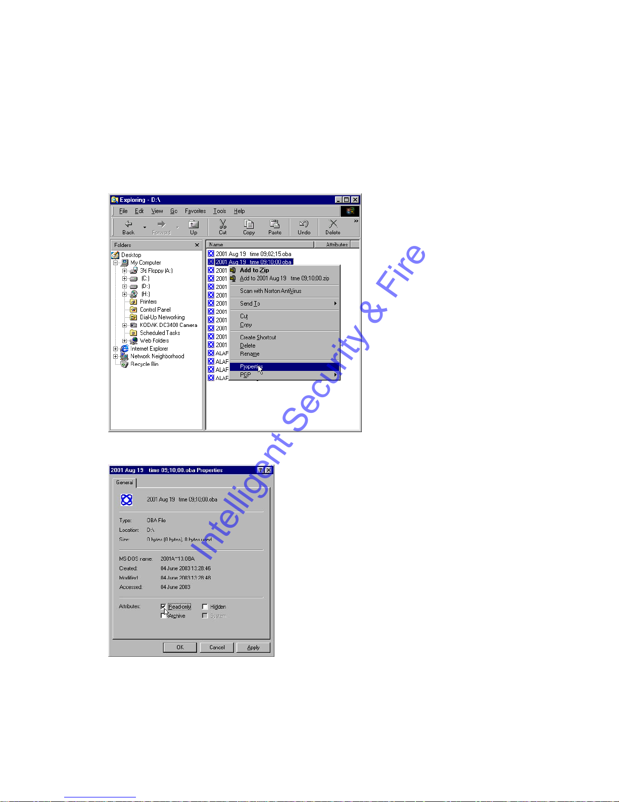
Write-Protection
Any file can be write-protected or un write-protected on the X100 or the PC. The recorder will
not overwrite write-protected files. To change the protection of a file on the X100 please see the
menu section of the manual. To change the protection on the PC, right click on the file and
select properties. Then tick or untick the Read-only flag of the file. Read-only (R) corresponds
to Write-protected (W) in the X100 recording history menu. If a file is write-protected on the
PC, and the disk is re-inserted back into the recorder, the recorder will treat it as write-protected
and not overwrite it.
Right click file and select file properties
Change the read-only flag as required.
29
Intelligent Security & Fire
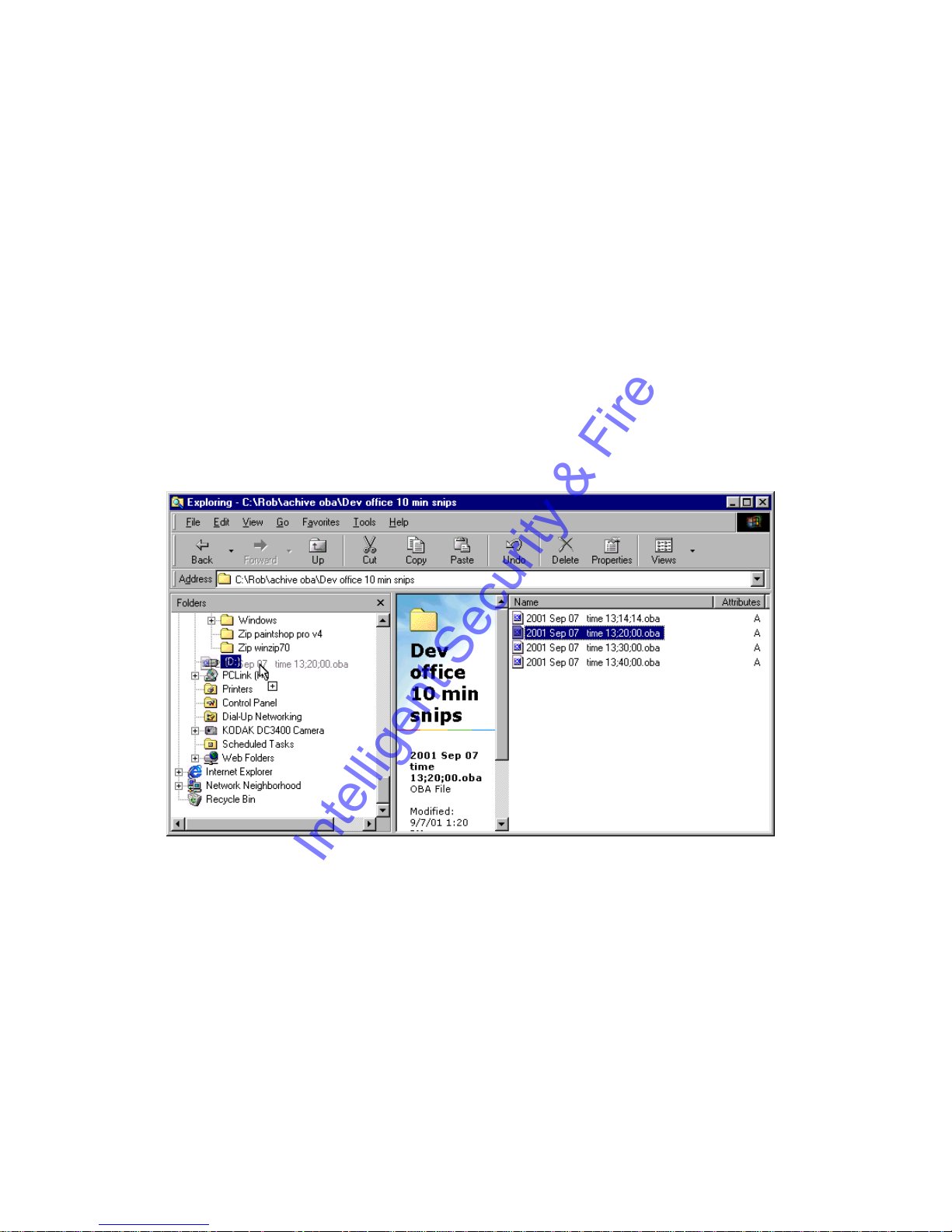
Putting footage back onto an X100
In certain circumstances it may be necessary to put files back onto a cartridge so that they may
be replayed by the X100. The following steps should be taken:
1 Put cartridge in an X100 and run a full reset (menu and recordings)
2 Connect disk via USB to PC (not forgetting to unplug and plug the USB connector as a last
step in the connection for each disk). The PC should pick up the disk containing two hidden
files SYSTEM and SYSTEM_B
3 Run Scandisk on the drive. This corrects the free disk size (which shows full on Windows
98, ME, XP) and allows files to be copied to the disk. To run scandisk right click the disk drive
letter of the cartridge (in the picture below the D: on the left hand side) then going to Properties>Tools->Check Now->Scandisk and using a Standard Test press start. Correct the single error
message that appears (reported free space not correct).
4 Drag the source .oba file(s) into the disk as shown below.
The disk will now be playable on the X100.
Dragging a file into D: the X100 cartridge
30
Intelligent Security & Fire
 Loading...