


Contents
1. About This Manual ..................................................................................................... 1
1.1 DVR Models – identification and distinction ........................................................ 1
1.2 Structure of this manual ...................................................................................... 2
2. Quick Start Guide ....................................................................................................... 3
2.1 System Overview ................................................................................................ 3
2.1.1 X500/R500 Digital Video/Audio Recording System ............................................. 4
2.1.2 Programming – X301 Reviewer ............................................................................ 4
2.1.3 Help Screens ......................................................................................................... 5
3. User Guide – X500/R500 Menu System ...................................................................... 7
3.1 Main Menu ......................................................................................................... 9
3.1.1 Normal Recording .............................................................................................. 11
3.1.2 Timer Recording ................................................................................................. 13
3.1.3 Alarm Recording ................................................................................................. 15
3.1.4 IP Cameras .......................................................................................................... 27
3.1.5 SD Recording ...................................................................................................... 39
3.1.6 Motion Detection – X500 only ........................................................................... 52
3.1.7 Audio Recording ................................................................................................. 59
3.1.8 X500 Audio ......................................................................................................... 60
3.1.9 Recorded Files .................................................................................................... 67
3.1.10 Video Output ...................................................................................................... 69
3.2 Settings Menu ................................................................................................... 75
3.2.1 System Settings .................................................................................................. 75
3.2.2 Time and date ..................................................................................................... 76
3.2.3 Alarm Inputs/Outputs Menu .............................................................................. 78
3.2.4 Camera Settings ................................................................................................. 79
i

3.2.5 File System .......................................................................................................... 82
3.2.6 System Info ......................................................................................................... 86
3.2.7 System Security .................................................................................................. 87
3.2.8 Power Options .................................................................................................... 90
3.2.9 Voltage Menu ..................................................................................................... 97
3.2.10 GSensor .............................................................................................................. 98
3.2.11 Vehicle ID .......................................................................................................... 101
3.2.12 Resource Allocation .......................................................................................... 102
3.2.13 Reset ................................................................................................................. 105
3.3 External Equipment .......................................................................................... 109
3.3.1 VLAN ................................................................................................................. 110
3.3.2 VLAN1 (COMMS) .............................................................................................. 111
3.3.3 VLAN2 (IP CAMERAS) ........................................................................................ 113
3.3.4 VLAN Scheme ................................................................................................... 114
3.3.5 GPS ................................................................................................................... 115
3.3.6 Remote ............................................................................................................. 117
3.3.7 PTZ Cameras ..................................................................................................... 118
3.3.8 SMTP Email ....................................................................................................... 120
3.3.9 CANLink ............................................................................................................ 122
3.4 Advanced Menu ............................................................................................... 123
3.4.1 Health Page Display .......................................................................................... 124
3.4.2 Service Log ........................................................................................................ 125
3.4.3 Load Software/Settings .................................................................................... 127
3.4.4 Save Software/Settings .................................................................................... 128
4. System Information And Security ............................................................................ 129
4.1 Language Selection........................................................................................... 129
4.2 Video Standard - PAL and NTSC ........................................................................ 129
ii

4.3 Timespace File System...................................................................................... 129
4.4 Video Compression .......................................................................................... 130
4.5 Audio ............................................................................................................... 132
4.5.1 X500 Audio ....................................................................................................... 132
4.5.2 R500 Audio ....................................................................................................... 132
4.6 PC Access Precautions ...................................................................................... 133
4.7 PC Network Access ........................................................................................... 134
4.8 Watermark and Sequencing ............................................................................. 135
4.8.1 Watermark ....................................................................................................... 135
4.8.2 Sequencing ....................................................................................................... 135
4.8.3 Watermark / Sequencing Report ..................................................................... 136
5. System Interfaces ................................................................................................... 137
5.1 GPS interface ................................................................................................... 137
5.2 Remote Operation ( LAN / Wifi / 3G) – Telnet / FTP .......................................... 139
5.3 RS232 / TELNET External Control ...................................................................... 140
5.4 USB Interface Kit .............................................................................................. 141
6. Installation Guide ................................................................................................... 143
6.1 Safety .............................................................................................................. 143
6.2 Environmental ................................................................................................. 143
6.2.1 Shock And Vibration ......................................................................................... 143
6.2.2 EMC .................................................................................................................. 143
6.2.3 Conformity ........................................................................................................ 143
6.2.4 Recycling ........................................................................................................... 143
6.3 Warnings ......................................................................................................... 144
6.4 X500/R500 Connections ................................................................................... 145
6.4.1 X500/R500 Front Panel .................................................................................... 145
iii

6.4.2 Reviewer Connector ......................................................................................... 146
6.4.3 X500 Rear Interface .......................................................................................... 147
6.4.4 R500 Rear Interface .......................................................................................... 149
6.5 Installation Instructions .................................................................................... 151
6.5.1 GSensor configuration ...................................................................................... 151
6.5.2 Installation Check List (Example)...................................................................... 152
6.5.3 Mechanical Data ............................................................................................... 153
6.5.4 Mounting kits ................................................................................................... 155
6.5.5 X500 on Vehicle Mounting Plate ...................................................................... 158
6.5.6 R500 on Vehicle Mounting Plate ...................................................................... 162
6.5.7 X500 and R500 – Final Mounted Clearances Required .................................... 166
6.5.8 Installation Spare Parts List .............................................................................. 168
7. Service And Maintenance ........................................................................................ 169
7.1 Maintenance .................................................................................................... 169
7.2 Service And Fail LED ......................................................................................... 169
7.3 Service Codes ................................................................................................... 170
8. Software ................................................................................................................. 173
8.1 X500/R500 Software and Updates .................................................................... 173
8.1.1 Software Upload ............................................................................................... 173
8.1.2 Software Download .......................................................................................... 173
8.1.3 Loading software from PCLink ......................................................................... 174
8.2 PCLink Suite ..................................................................................................... 176
9. Appendices ............................................................................................................. 179
APPENDIX 1 – X500 and R500 specifications and technical data ...................................... 179
APPENDIX 2 – EC conformity certificates ..................................................................... 182
APPENDIX 3 – Splash Screen ...................................................................................... 187
iv

APPENDIX 4 – Tokens / Protocol ................................................................................. 188
v

List of Figures
Figure 1 - X500/R500 Identification and distinction .................................................................. 1
Figure 2 - X500 and R500 - Features and differences ................................................................ 1
Figure 3 X500/R500 Digital Video/Audio Recorder .................................................................... 3
Figure 4 X301 Reviewer ..................................................................................................... 4
Figure 5 - Recording Resource Requirements and IPS Allocation .......................................... 103
Figure 6 - Image quality and bit rates (Analogue (SD) cameras) ........................................... 130
Figure 7 - Network ports ........................................................................................................ 134
Figure 8 - X500/R500 with Reviewer ...................................................................................... 146
Figure 9 - X500 Rear Interface ................................................................................................ 147
Figure 10 - X500 Connections/Wiring .................................................................................... 148
Figure 11 - R500 Rear Interface .............................................................................................. 149
Figure 12 - R500 Connections/Wiring .................................................................................... 150
Figure 13 - X500 Mechanical Data ......................................................................................... 153
Figure 14 - R500 Mechanical Data ......................................................................................... 154
Figure 15 - Vehicle Mounting System - Mounting Hole Preparation ..................................... 155
Figure 16 - Wire Rope Mounts ............................................................................................... 156
Figure 17 - Timespace Vehicle Mounting Plate System parts ................................................ 157
Figure 18 – X500 on Vehicle Mounting Plate – (front-back) .................................................. 158
Figure 19 - X500 on Vehicle Mounting Plate (left-right) ........................................................ 159
Figure 20 - X500 on Vehicle Mounting Plate (side) ................................................................ 160
vi

Figure 21 - X500 on Vehicle Mounting Plate – open .............................................................. 161
Figure 22 - X500 on Vehicle Mounting Plate – closed............................................................ 161
Figure 23 - R500 on Vehicle Mounting Plate (front-back) ..................................................... 162
Figure 24 - R500 on Vehicle Mounting Plate (left-right) ........................................................ 163
Figure 25 - R500 on Vehicle Mounting Plate (side) ................................................................ 164
Figure 26 - R500 on Vehicle Mounting Plate – open ............................................................. 165
Figure 27 - R500 on Vehicle Mounting Plate - closed ............................................................ 165
Figure 28 - X500 on Vehicle Mounting Plate – final mounted clearance (front) ................... 166
Figure 29 - X500 on Vehicle Mounting Plates - final mounted clearance (side) .................... 166
Figure 30 - R500 on Vehicle Mounting Plates - final mounted clearance (front) .................. 167
Figure 31 - R500 on Vehicle Mounting Plates - final mounted clearance (side) .................... 167
vii

List of Abbreviations
Abbreviation
Meaning
AUX
Auxiliary
bps
Bits per second
CAN
Controller Area Network
CD
Compact Disk
CE
European Conformity
COM
Communication (port)
COMMS
Communications
DVR
Digital video recorder
EEC
European Economic Community
EMC
Electro-magnetic compatibility
EMG
Emergency (EMG Splash Screen)
FAT
File Allocation Table
FMS
Fleet Management System
FTP
File Transfer Protocol
FPS
Frames Per Second
GB
Gigabytes
GMT
Greenwich Mean Time
GND
Ground
GPS
Global positioning System
GSM
Global system (or standard) for mobile
HDD
Hard Disk Drive
HR
Hour
IP
Internet Protocol
IPS
Images per second
kHz
Kilohertz
KPH
Kilometres Per Hour
LAN
Local Area Network
LED
Light-Emitting Diode
viii

MAC
Media Access Control
MB
Megabytes
MBR
Master Boot Record
MED
Medium
mics
Microphones
MIN
Minute
MPH
Miles Per Hour
NTSC
The television broadcasting system used in North America and Japan
OSD
On-screen display
ONVIF
Open Network Video Interface Forum
PAL
Phase Alternating Line
PC
Personal Computer
PCB
Printed Circuit Board
PoE
Power over Ethernet
PTZ
Pan Tilt Zoom (camera)
RES
Resolution
RH
Relative Humidity
RMS
Root Mean Square
RTSP
Real Time Streaming Protocol
s
Second
SD
Secure Digital (card)
SDHC
Secure Digital High Capacity
SEC
Second
SMART
Self-Monitoring, Analysis and Reporting Technology
SMS
Short Message System
TB
Terabyte
TCP
Transmission Control Protocol
UK
United Kingdom
URL
Uniform Resource Locator (address of specific website or file on the internet)
USA
United States of America
USB
Universal Series Bus (cable system)
ix

UTC
Co-ordinated Universal Time
V
Volts
VOR
Voice Operated Recording
Vrms
Root-mean-square Voltage
W
Watts
WiFi
Wireless local area network
x
X500 and R500 Instruction Manual Chapter 1 – About This Manual
X500 Digital Video Recorder
R500 Digital Video Recorder
Feature
X500
R500
Analogue (SD) video inputs
4
4
IP Video inputs
4 (PoE)
4 (non PoE)
Video outputs 2 1
Audio inputs
1 standard + 4 High Quality
1 standard quality
Alarms in 6 10
Built in camera power/connector
No
Yes (GX12 4-way)
Motion Detection
Yes, IP and analogue
No
1. About This Manual
This manual contains the information required for the installation and operation of the Timespace
Technology X500 and R500 Digital Video Recorders (DVRs).
The X500 and R500 DVRs utilise the same software. The software menus are therefore largely the
same, and are covered in the same section of this manual (User Guide – X500/R500 Menu System).
Where there are differences in the menu screens/settings, different screenshots will be given for the
X500 and the R500 and the options/settings explained accordingly.
However there are differences between the X500 and the R500 in number and type of cameras,
number and type of audio connections etc. The photographs, diagrams, connection details and
installation instructions in this manual are therefore specific to either the X500 or R500 and are
labelled as such.
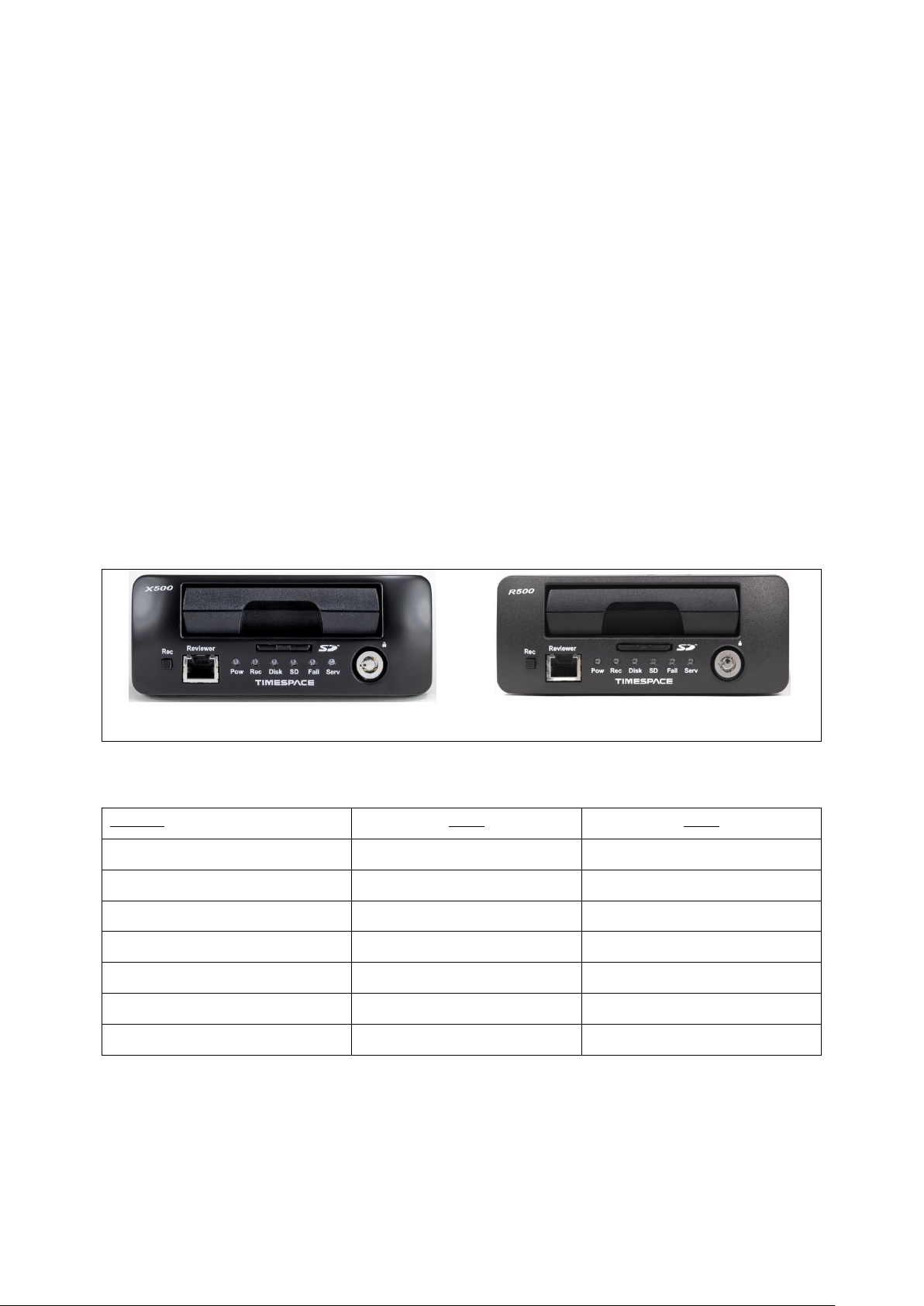
1.1 DVR Models – identification and distinction
The X500 and the R500 have identical front panels, other than the X500/R500 DVR model labelling.
Figure 1 - X500/R500 Identification and distinction
A summary of the main feature differences between the X500 and the R500 is below:
Figure 2 - X500 and R500 - Features and differences
1

X500 and R500 Instruction Manual Chapter 1 – About This Manual
1.2 Structure of this manual
This manual is divided into the following sections:
(Chapter 1 – About this manual)
Chapter 2 – Quick Start Guide
Chapter 3 – User Guide – X500/R500 Menu System
Chapter 4 – System Information and Security
Chapter 5 – System Interfaces
Chapter 6 – Installation Guide
Chapter 7 – Service and Maintenance
Chapter 8 – Software
Appendices
Where text in the body of the manual is shown in CAPITALS, this relates to one of the menu choices
in the DVR menu system, eg MAIN MENU > NORMAL RECORDING.
Within the User Guide section of the Manual, links from menus to other menus or sub-menus are
given as hyperlinks.
Detailed technical information can be found in the Appendices, along with certificates of conformity
and type approval.
2
X500 and R500 Instruction Manual Chapter 2 – Quick Start Guide
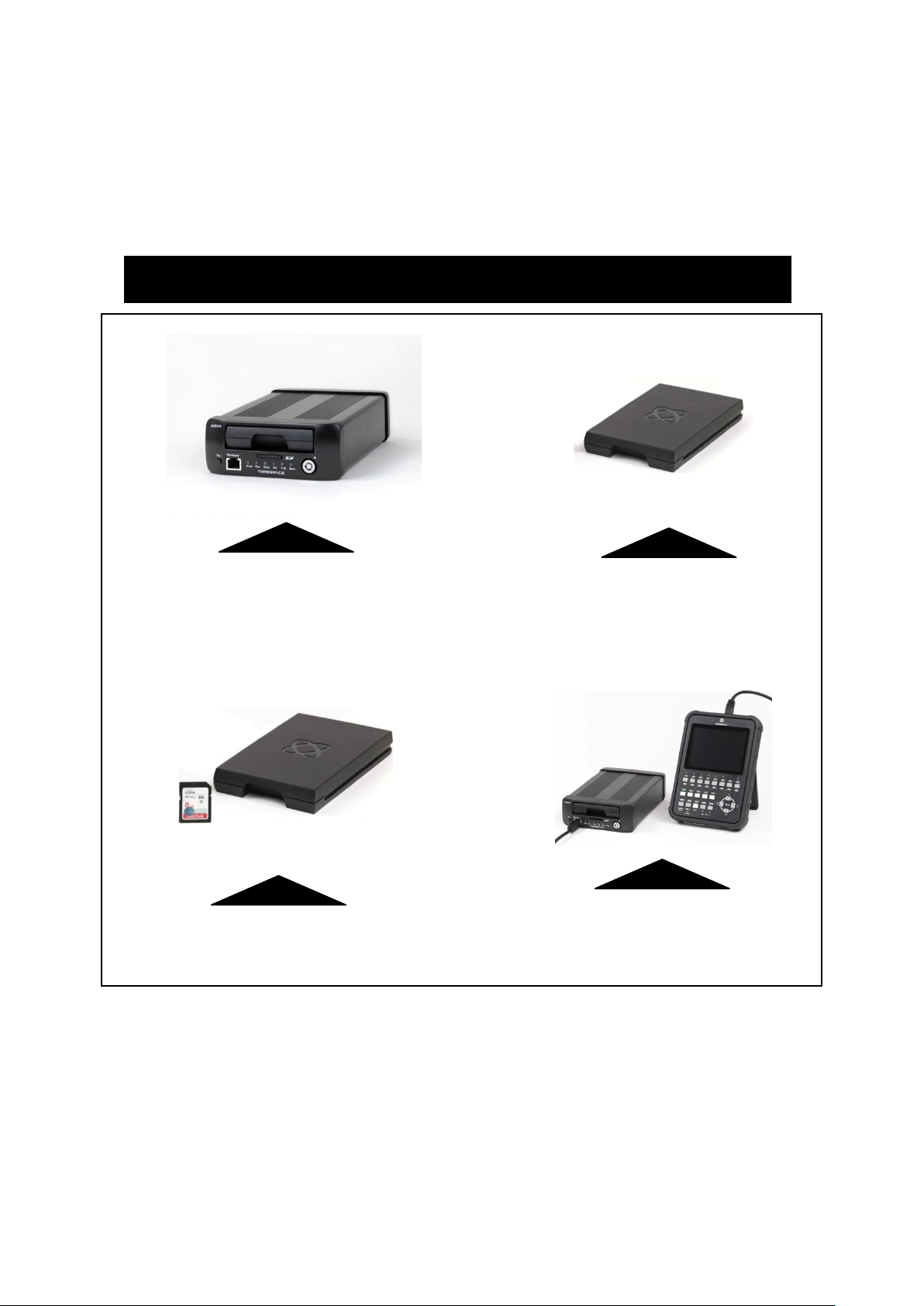
X500/R500 DIGITAL VIDEO / AUDIO RECORDER
REMOVABLE, SHOCK MOUNTED
HARD DISK CARTRIDGE
REMOVABLE SD CARD FOR DUAL
RECORDING & DOWNLOAD (OPTIONAL)
X500/R500 with
X301 REVIEWER / PROGRAMMER
X500 DIGITAL VIDEO/AUDIO RECORDING SYSTEM
2. Quick Start Guide
2.1 System Overview
Figure 3 X500/R500 Digital Video/Audio Recorder
3

X500 and R500 Instruction Manual Chapter 2 – Quick Start Guide
2.1.1 X500/R500 Digital Video/Audio Recording System
The X500 and R500 are digital video/audio surveillance recorders (DVRs) for use in covert, portable
and mobile applications.
Recordings are made on a removable hard disk cartridge inserted in the DVR. Optionally, recordings
can be simultaneously written to a removable SD card.
The recordings can be accessed by connecting the cartridge to a PC using the USB interface kit or
cartridge station (both available from Timespace). Timespace PCLink application is a proprietary
reading and archiving software package used to review the recordings.
The Timespace X301 Reviewer is used to program the menu settings on the DVR, to check camera
views, to playback footage and to list the recorded files on the installed Hard Disk Cartridge.
The DVR’s integral GSensor records the vehicle’s movement for the X, Y & Z axes.
2.1.2 Programming – X301 Reviewer
The DVR is configured using a tiered menu system. The menu system is accessed using the X301
Reviewer (pictured below).
Figure 4 X301 Reviewer
To enter the Menu System press any of the four MENU arrow buttons.
To exit the Menu System or to move back up a level press the MENU EXIT button.
See the separate X301 Reviewer manual at www.tspace.co.uk for detailed information on the
Reviewer’s functions / controls, including PTZ controls.
4

X500 and R500 Instruction Manual Chapter 2 – Quick Start Guide
2.1.3 Help Screens
Each page on the DVR menu system has an associated Help screen which describes the features on
that page.
Pressing the HELP key on the Reviewer front panel will display the Help page. Use the UP/DOWN
arrow keys to scroll through each help page.
The help pages included on the DVR are intended as a quick reference with more detailed
descriptions contained in this manual.
5


X500 and R500 Instruction Manual Chapter 3 – User Guide – X500/R500 Menu System
3. User Guide – X500/R500 Menu System
The DVR is configured using a tiered menu system. There are two top level menus through which all
features and settings are configured.
The MAIN MENU relates to the recording functions, files and video output:
The SETTINGS MENU is where the DVR and any connected equipment are configured:
7

X500 and R500 Instruction Manual Chapter 3 – User Guide – X500/R500 Menu System
A help system is included and can be displayed for each menu by pressing the HELP key on the
Reviewer.
Navigation of the menu system is by using the arrow keys on the Reviewer.
All menu configuration items are changed instantly with the exception of the following which require
a reboot:
VIDEO STANDARD – switching between PAL/NTSC.
BAUD RATE – changing the baud rate for GPS, GSensor and RS232.
LANGUAGE FILE – when loading a language file from the hard disk cartridge.
8
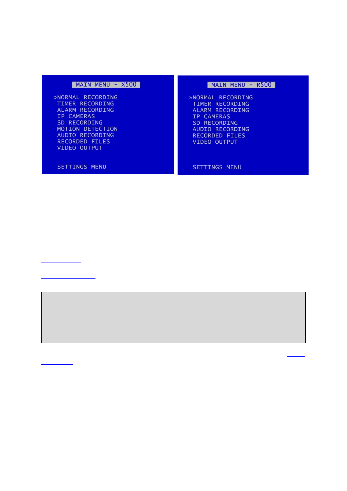
X500 and R500 Instruction Manual Chapter 3 – User Guide – X500/R500 Menu System
X500 Main Menu
R500 Main Menu
HINT: A MANUAL OVERRIDE feature exists. If the DVR is recording from a configured recording
setting, eg TIMER RECORDING or ALARM RECORDING, and a user attempts to stop recording (by
pressing the REC button on the Reviewer or on the X500 front panel), a warning message will be
displayed. “MANUAL OVERRIDE ENABLED”. To disable MANUAL OVERRIDE, press the record key
again. To cancel the action, press the MENU EXIT key.
3.1 Main Menu
Recording modes in order of priority are:
1) ALARM RECORDING
2) TIMER RECORDING
3) NORMAL RECORDING
SD RECORDING can be running in parallel to any of the above recording modes.
MOTION DETECTION is used as a trigger to start one of the recording modes - it is not a recording
mode on its own.
Audio recording can be turned on or off for all recording modes. This selection is found on the AUDIO
RECORDING menu where other specific audio settings can be configured.
Only one mode is active at any one time. For example if ALARM RECORDING occurs during NORMAL
RECORDING, ALARM RECORDING takes control but reverts back to NORMAL RECORDING once
ALARM RECORDING has finished.
9

X500 and R500 Instruction Manual Chapter 3 – User Guide – X500/R500 Menu System
NB: Across the different recording modes, the DVRs have some common settings, e.g. Images per
Second (IPS). The IPS can be configured from 1 to 25 per camera. To save duplication, these
options will only be documented in the first instance and subsequent features should be assumed
to be the same unless explicitly stated.
10
X500 and R500 Instruction Manual Chapter 3 – User Guide – X500/R500 Menu System
HINT: A “copy down” feature is available for configuring multiple analogue camera settings. The
settings for the currently selected camera will be copied down to all remaining cameras, subject
to the global IPS limit. Press 0 to copy down.
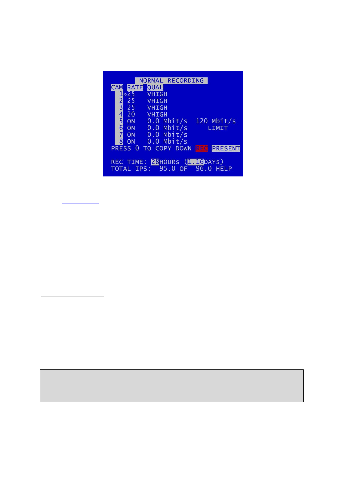
3.1.1 Normal Recording
This menu sets the Normal Recording configuration. Recording is activated by pressing the record
button on the front of the DVR or the Reviewer. In addition, recording can be activated on ignition or
with an ALARM INPUT.
The X500 and the R500 each have 8 camera inputs:
Cameras 1-4 are the analogue (SD) cameras.
Cameras 5-8 are the IP cameras.
It is possible to “dual record”, ie record analogue and IP cameras at the same time.
Connected cameras are identified by highlighting the relevant camera number with either a red
background (indicating camera recording) or a white background (camera present but not recording).
Analogue (SD) cameras:
Images per second IPS (RATE) and image quality (QUAL) can be set individually for each analogue
camera.
RATE can be set to; “-“ (OFF), 1, 1.5, 2, 3, 4, 5, 6, 7, 8, 9, 10, 12.5, 15, 20, 25. The global (total)
maximum IPS limit on the X500/R500 is 100 IPS.
QUAL can be set to; LOW, MEDIUM, HIGH, V.HIGH, VV.HIGH, SUPER
11

X500 and R500 Instruction Manual Chapter 3 – User Guide – X500/R500 Menu System
By default the DVR is set to NORMAL RECORD on all connected analogue (SD) cameras, enabling
quick deployment - just connect cameras and press the record button.
IP cameras need to be configured separately, see IP Cameras section.
NB: the DVR is set to default record at power up. Options to enable/disable recording at powerup are found in the SETTINGS > ADVANCED > POWER STATE.
NB: if IP cameras are enabled, IP camera streams will be recorded along with the analogue
recording streams configured in eg NORMAL RECORDING, TIMER RECORDING, ALARM
RECORDING etc.
In addition, IP Cameras can record as a stand-alone function even if no analogue cameras are
configured. Ensure that the desired number of IP Cameras are selected in the NORMAL, TIMER or
ALARM RECORDING menus.
IP cameras:
To configure IP Cameras, eg IP addresses, see the separate menu section MAIN MENU > IP CAMERAS
3.1.1.1 REC TIME AND TOTAL IPS
The global (total) recording resource available on the X500/R500 is 100 IPS.
For each recording mode, the total number of configured IPS (images/sec) is displayed along with the
maximum. Any adjustment to the camera IPS, image quality or number of recorded cameras will
affect the REC TIME. The REC TIME is an indication of the number of Days, Hours, Minutes that the
DVR will record for based upon the current settings and entire installed cartridge capacity.
HELP – provides details of currently configured RESOURCE ALLOCATION across the various functions.
12
X500 and R500 Instruction Manual Chapter 3 – User Guide – X500/R500 Menu System
HINT: A “copy down” feature is available for configuring multiple analogue camera settings. The
settings for the currently selected camera will be copied down to all remaining cameras, subject
to the global IPS limit. Press 0 to copy down.
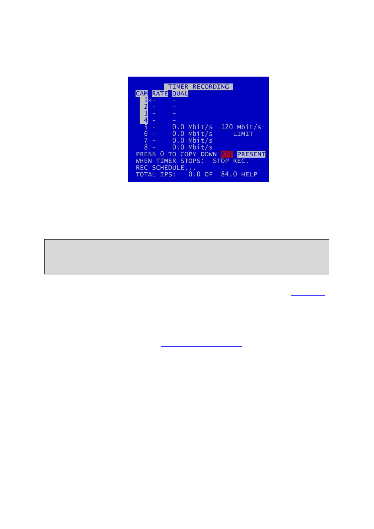
3.1.2 Timer Recording
Daily on/off timers can be set to provide timed recording. This menu sets the recording configuration
and the time. During TIMER RECORDING the settings in this menu apply.
Images per second (RATE) and image quality (QUAL) can be set for each analogue camera (Cameras
1-4) in the same way as for NORMAL RECORDING.
IP Cameras can be used for TIMER RECORDING and can be configured at MAIN MENU > IP CAMERAS
WHEN TIMER STOPS: At the end of a period of TIMER RECORDING the DVR can either STOP
RECORDING or record in NORMAL RECORDING record mode. The latter can be used if two recording
styles are required based on time.
Enter the daily start and end times in the REC (RECORDING) SCHEDULE menu
TOTAL IPS – provides details of current IPS allocation within TIMER RECORDING, ie configured images
per second, as well as the total IPS available for TIMER RECORDING.
HELP – provides details of recording RESOURCE ALLOCATION across the various functions.
13
X500 and R500 Instruction Manual Chapter 3 – User Guide – X500/R500 Menu System
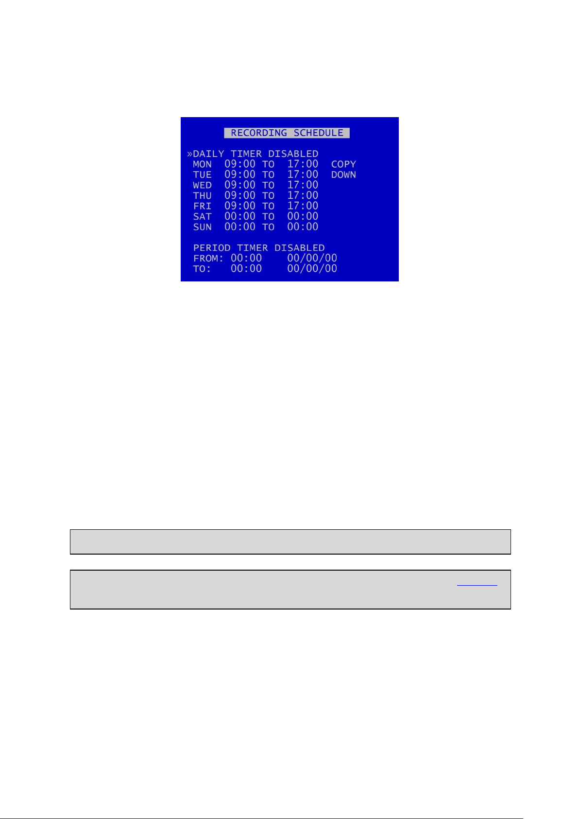
NB: By default the TIMER SCHEDULE is set to Mon-Fri 9-5 and all day Sat/Sun.
HINT: Times are entered in the SCHEDULE using the digit keys on the front panel of the Reviewer
for number input.
3.1.2.1 Recording Schedule
A RECORDING SCHEDULE can be set. This can be used e.g. to record between a start date and end
date. If both DAILY TIMES and PERIOD TIMES are selected, the DVR will record only in the period and
also only in the daily times shown.
DAILY TIMER DISABLED – disables timer recording.
RECORD BETWEEN DAILY TIMES – sets the unit to record between the daily times specified in the
schedule.
RECORD OUTSIDE DAILY TIMES – sets the unit to record at all times other than those specified in the
daily times schedule.
A COPY DOWN features is available to copy the times set for Monday on to all other days of the
week.
A period of TIMER RECORDING can be set e.g. to record between a start date and end date. Options
for this are PERIOD TIMER DISABLED, RECORD INSIDE PERIOD, RECORD OUTSIDE PERIOD.
If the daily timer and the period timer are both enabled, then recording occurs in the intersection of
the daily timer and period timer settings.
14
X500 and R500 Instruction Manual Chapter 3 – User Guide – X500/R500 Menu System
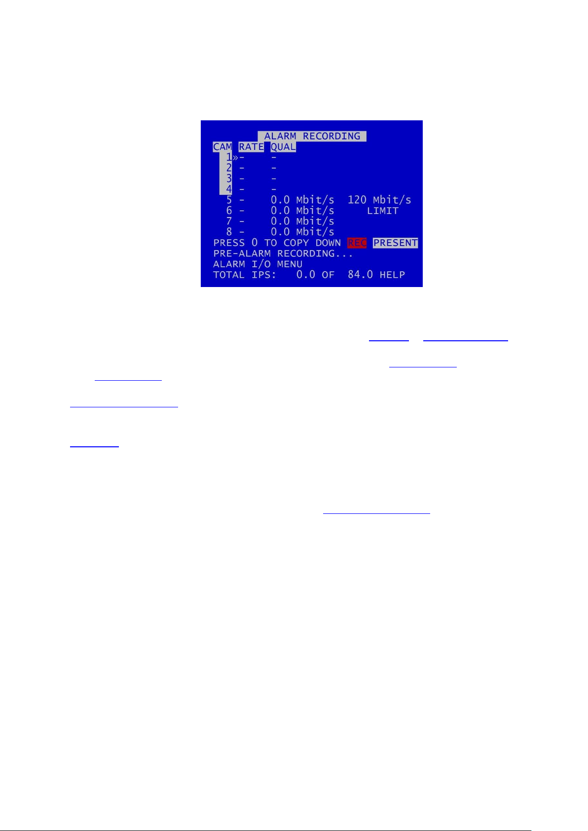
3.1.3 Alarm Recording
Alarm recording is activated by the alarm inputs. This menu sets the alarm recording configuration.
Configure camera RATE and QUAL, and configure IP cameras, as for NORMAL or TIMER RECORDING.
Alarm recording can be triggered by setting the function of one or more ALARM INPUTS to be ALARM
REC. ALARM INPUTS can also be used to trigger other functions and modes of recording.
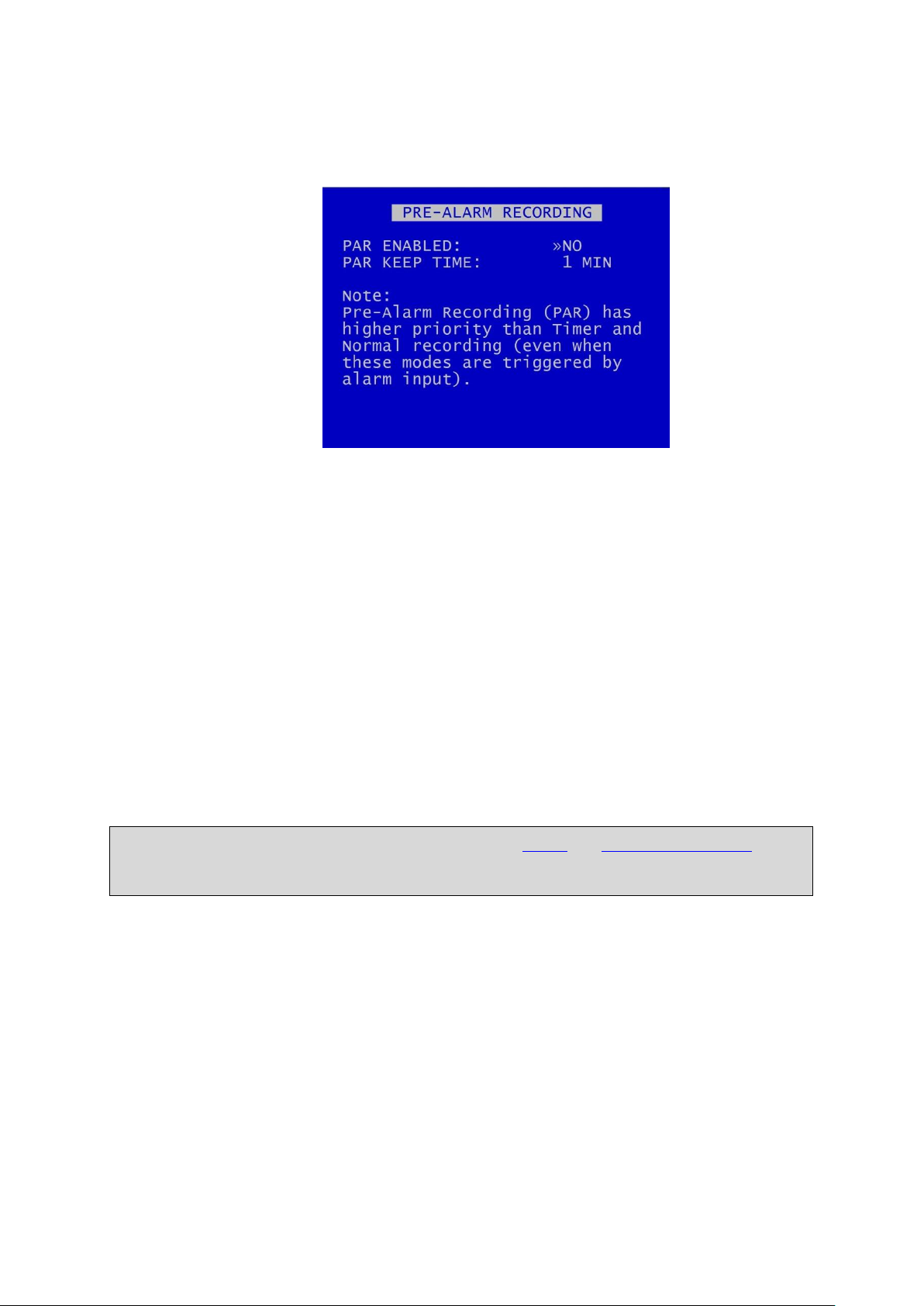
PRE-ALARM RECORDING – configures the DVR to capture and retain a period of recording prior to an
alarm input being triggered.
ALARM I/O sub menu configures Alarm Recording options and INPUT / OUTPUT options.
Total IPS – provides details of current IPS allocation within ALARM RECORDING, as well as the total
IPS available for ALARM RECORDING.
HELP – provides details of currently configured recording RESOURCE ALLOCATION across the various
recording functions.
15
X500 and R500 Instruction Manual Chapter 3 – User Guide – X500/R500 Menu System
NB: Pre-Alarm Recording (PAR) has a higher priority than TIMER and NORMAL RECORDING (even
when these modes are triggered by an alarm input).
3.1.3.1 Pre-Alarm Recording
Pre-Alarm Recording (PAR), if enabled, configures the DVR to record for a set period of time prior to
an alarm input being triggered, and for the DVR to keep the PAR files. This is useful in order to
ensure that the lead-up to an alarm event is recorded. It avoids the need to have the DVR recording
permanently, and it maximises the amount of available hard disk space, while ensuring that the
recorded files for alarm event lead-up are kept.
PAR ENABLED – to allow PRE-ALARM RECORDING, select YES. To disable PAR, select NO.
PAR KEEP TIME – select the length of pre-alarm footage which you wish to retain on the disk.
Options are 1MIN, 2, 3, 4, 5, 10, 20, 30, 40, 50MINS, 1HOUR, UNLIMITED.
The DVR will record all cameras specified for ALARM RECORDING for the duration specified in the
PAR KEEP TIME setting. The DVR will be recording continuously, but will only keep the recordings for
the specified time.
16
X500 and R500 Instruction Manual Chapter 3 – User Guide – X500/R500 Menu System
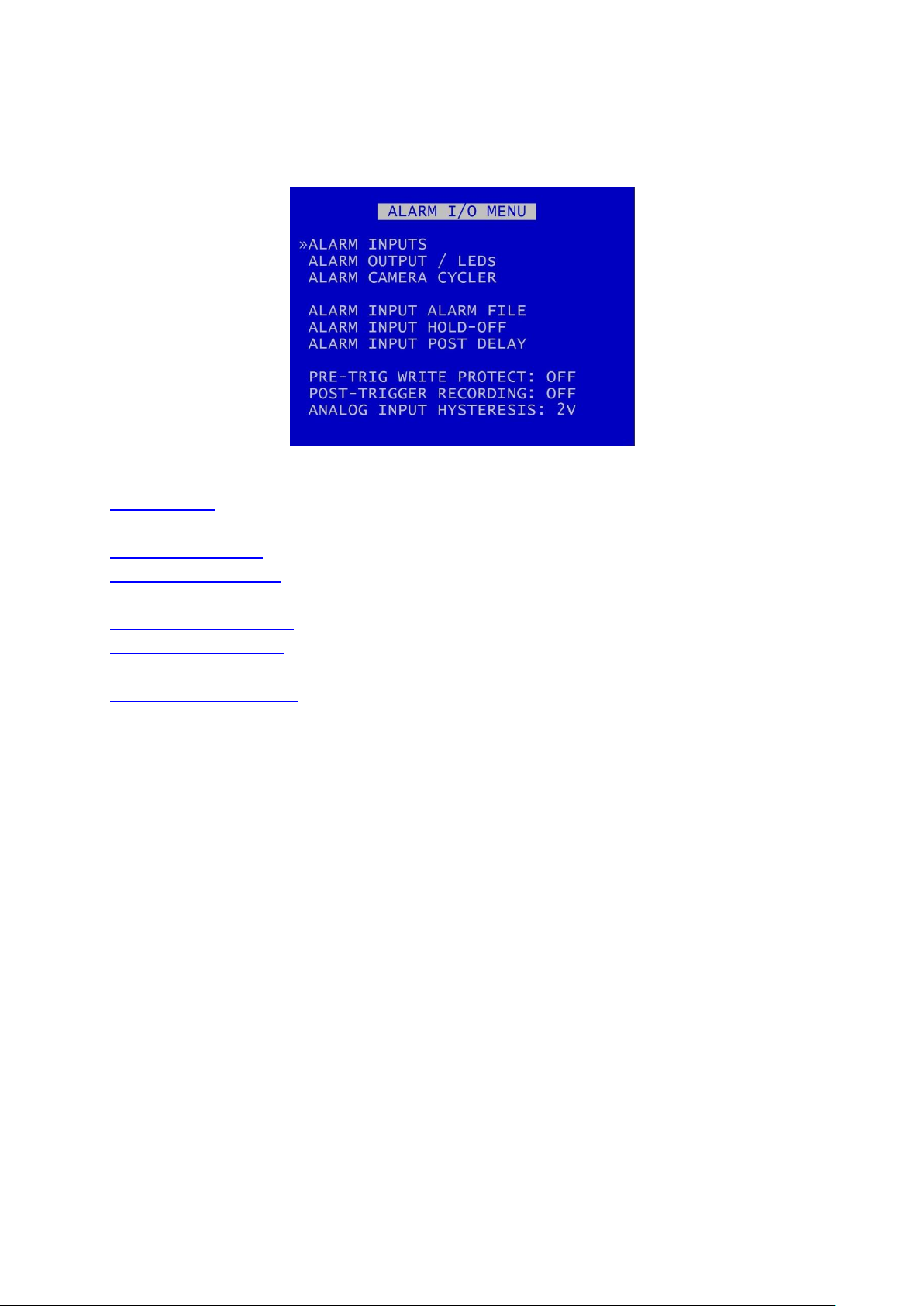
3.1.3.2 Alarm Inputs/Outputs
ALARM INPUTS – sets the active/inactive status of each alarm input and defines the function (action)
of the DVR when the selected alarm is active.
ALARM OUTPUT/LEDs – sets the conditions for the alarm outputs.
ALARM CAMERA CYCLER – configures the options for the DVR to automatically switch between
cameras and the Health Page.
ALARM INPUT ALARM FILE – provides an option for files to be marked as alarm recordings.
ALARM INPUT HOLD-OFF – controls the number of seconds for which ALARM RECORDING is delayed
after an alarm input has been triggered.
ALARM INPUT POST-DELAY – controls the number of seconds for which the alarm state is held once
the alarm input has changed state.
PRE-TRIG WRITE PROTECT specifies the duration prior to the alarm recording for which files will be
marked as write protected. This assumes that another mode of recording was already writing files to
disk. Select from available values: 1SEC, 2, 5, 10, 20, 30, 40, 50, 1MIN, 2, 5, 10, 20, 30, 40, 50MINS,
1HOUR, 2HOURS.
POST-TRIGGER RECORDING – specifies the duration of recording after the alarm trigger. Once posttrigger has elapsed, recording will stop or return to the previous recording mode. Post-trigger values
are: OFF, 1SEC, 2, 5, 10, 20, 30, 40, 50, 1MIN, 2, 5, 10, 20, 30, 40, 50MINS, 1HOUR, 2HOURS.
ANALOG INPUT HYSTERESIS – specifies the voltage value difference that must occur in order to
change the alarm state, eg if the trigger is set to 14V, when 14V is met the trigger will switch. In
order to switch back, a change of 2V must occur, ie 14-2 = 12V. Available values are: 1V, 2, 3, 4, 5, 6,
7and 8V.
17
X500 and R500 Instruction Manual Chapter 3 – User Guide – X500/R500 Menu System
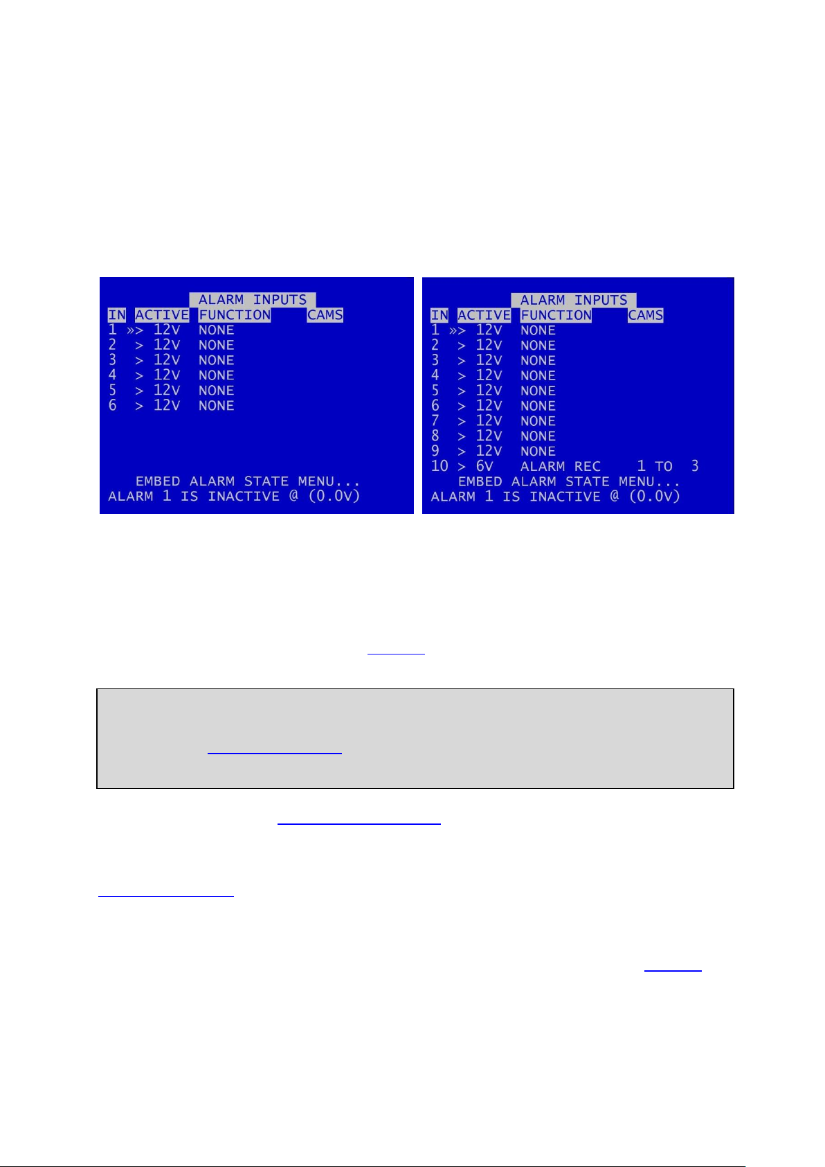
X500 Alarm Inputs
R500 Alarm Inputs
NB: There is a priority order on the Alarm Inputs. The lower numbered Alarm Inputs take priority
over the higher numbers. For example, if Alarm Input one is wired to the Reversing sensor, and is
set to to trigger NORMAL RECORDING when the Reversing sensor is activated, this alarm will take
priority over any other alarm currently triggered.
3.1.3.3 Alarm Inputs
The X500 has 6 alarm inputs on the screw terminal block – see Figure 10 - X500 Connections/Wiring.
The R500 has 10 alarm inputs on the screw terminal block – see Figure 12 - R500
Connections/Wiring.
ALARM INPUTS menu sets the alarm inputs to be ACTIVE or INACTIVE. If an alarm input number is
highlighted with a white background, this indicates its current state is active. No highlight indicates
the state is inactive.
Use the left and right menu buttons on the Reviewer to set the active voltage. For a 12V input, use
typically <6V or >6V to ensure a clear change in state triggers the alarm.
FUNCTION lists the available ALARM INPUT FUNCTIONS for selection. The FUNCTION defines the
action of the DVR when the selected alarm input is active. The function is active for the duration of
the alarm (plus post trigger time if selected):
EMBED ALARM STATE menu configures options for adding text to recorded images.
ALARM 1 IS INACTIVE @ - Shows the current state of each of the alarm inputs. The corresponding
number for each alarm input will be highlighted (white background) for ACTIVE and not highlighted
for INACTIVE. To view the current state for each alarm input, use the arrow keys on the Reviewer to
move up and down to each alarm number. The voltage is also shown.
18

X500 and R500 Instruction Manual Chapter 3 – User Guide – X500/R500 Menu System
NONE
-
No action
NORM REC
-
Switches NORMAL RECORDING on
ALARM REC
-
Switches ALARM RECORDING on.
TIMER REC
-
Switches TIMER RECORDING on
MAIN OUT
-
Sets the main video switcher (MAIN OUT) to the selected camera.
Alternatively select the multi-camera screen (MULTI) or Emergency Splash
Page (EMRSPL) to be displayed.
AUX1OUT
-
(X500 only)
Sets the auxiliary video switcher (AUX VIDEO OUT) to the selected camera.
EMAIL
-
Instructs the DVR to send an email. Configure this in EXTERNAL EQUIPMENT
>SMTP EMAIL.
HEALTH PAGE
-
Displays the DVR Health Page.
PTZ PRESET
-
Accesses the PTZ preset camera positions. 8 presets are available (setup
using the PTZ menu) and a trigger can be used to invoke that position upon
alarm state change.
IGNITION
-
Linked to POWER OPTIONS menu to control how the DVR behaves on
ignition
OVERLAYS
-
Various vehicle alarm inputs - tags the particular alarm inputs as used for:
INDICATOR L, INDICATOR R, BRAKE, SIDE LIGHTS, HEAD LIGHTS, FOG LIGHTS,
HORN, BULL HORN, SIREN, BLUES, HAZARD WARN, DOOR, REVERSE,
HANDBRAKE, ACCEL’TION, DOOR1, DOOR2, DOOR3, RAMP
CAM CYCLER
-
Automatically switches between cameras and the Health Page as configured
in the ALARM CAMERA CYCLER menu from the ALARM I/O menu page.
AUDIO REC
-
Must be used in conjunction with the AUDIO RECORDING menu, i.e.
enabling AUDIO RECORDING FOR NORMAL, TIMER, ALARM or
SD RECORDING.
BEEP TEST
-
This is used for test purposes only and is not required by users.
POWER DOWN
-
Instructs the DVR unit to power down when the alarm is triggered
PUSHBUTTON1 & 2
-
tags the alarm inputs as used for additional buttons/triggers specified by
the user
Alarm Input Functions
Each of the alarm inputs can be set to turn on/off the selected FUNCTION. The FUNCTION defines
the action of the DVR when the selected alarm input is active. The FUNCTION is active for the
duration of the alarm (plus POST-TRIGGER time if selected – see ALARM INPUTS/OUTPUTS menu).
If a recording mode is used as an alarm FUNCTION, the settings are as per the settings in the relevant
recording mode menu, eg if NORMAL RECORDING is selected as an alarm FUNCTION, the settings
configured in NORMAL RECORDING are used when that alarm is triggered.
19

X500 and R500 Instruction Manual Chapter 3 – User Guide – X500/R500 Menu System
X500 Embed Alarm State
R500 Embed Alarm State
3.1.3.4 Embed Alarm State
Text can be embedded into recorded images using the EMBED ALARM INPUT STATE menu.
8 user-defined characters can be entered per input, and positioned either top or bottom of the
image. The text will display on the footage for the duration of the alarm, plus any post-alarm
duration which has been configured.
EMBED – select YES or NO.
TEXT – default text is the alarm number. The default text is the number of each alarm, eg ALARM 1,
ALARM 2 etc. Alternative text can be entered using the Reviewer.
POSITION – select TOP or BOTTOM
The text will be embedded on all camera views simultaneously and will appear on all selected
cameras during playback in PCLink.
20

X500 and R500 Instruction Manual Chapter 3 – User Guide – X500/R500 Menu System
X500 Alarm Outputs
R500 Alarm Outputs
TEST OPEN/CLOSED
-
Sets the input to OPEN/CLOSED for testing purposes
ALARM OCCURRED
-
An ALARM event has occurred
RECORD LED
-
The front panel record LED is active
DISK LED
-
The front panel disk LED is active
SD RECORDING
-
SD recording is occurring
FAIL LED
-
The front panel fail LED is active
SERVICE LED
-
The front panel service LED is active
FRONT LEDS
-
Any of the front panel LEDs are active
CAM DISCONNECTED
-
Any camera is disconnected
GSENSOR TRIGGER
-
Any of the GSensor configured thresholds are reached / exceeded
LAN ACTIVE
-
Files are being transferred via the LAN interface
3.1.3.5 Alarm Outputs
The ALARM OUTPUT menu sets the conditions for the external alarm outputs.
The X500 has 3 alarm outputs: LED1 (LD1), LED2 (LD2) and ALARM (ALM).
The R500 has one alarm output: ALARM (ALM).
ACTIVE – CLOSED contact means alarm terminals connected, OPEN contact means alarm terminals
unconnected. When CLOSED, the alarm output number will be highlighted in white. When open, no
highlight is shown.
Select WHEN the alarm will change state/be activated:
21

X500 and R500 Instruction Manual Chapter 3 – User Guide – X500/R500 Menu System
HD WP %
-
A percentage of the hard disk cartridge contains Write-Protected files:
25, 50, 60, 70, 80, 90 and 99%.
HD FULL %
-
A percentage of the hard disk cartridge if full; 25, 50, 60, 70, 80, 90 and
99%.
AUDIO VOR
-
Voice Operated Recording. If the detected level of audio input reaches
a certain percentage (25%, 50%, 75%) the alarm output can be
triggered (using ALARM OUTPUTS). If using this trigger as an alarm
input, a wire link will need to be in place on the X500 rear panel green
block (seeFigure 10 - X500 Connections/Wiring and Figure 12 - R500
Connections/Wiring ). If the VOR output is being used as an alarm input
to trigger recording, it can only be used to trigger ALARM recording
mode. Example setup of VOR;
1. ALARM OUTPUT: ALM, CLOSED, AUDIO VOR 75%
2. ALARM INPUT: LD1, CLOSED, FUNCTION – ALARM REC, CAMS 1
The above example assumes that there is a wire link on the green block
between ALARM OUT and ALARM IN1. The POST TRIGGER time can also
be set to record for x seconds after the audio trigger has finished.
MOTION DETECTED
-
(X500 ONLY) Motion has been detected.
GPS SPEED ALARM
-
GPS has detected speed above a certain designated threshold.
Configure this in the GPS menu.
CURRENT STATE – Describes how each alarm output is CLOSED (highlighted white) or OPEN (no
highlight) (CLOSED showing alarm terminals are connected; OPEN showing alarm terminals are not
connected).
22

X500 and R500 Instruction Manual Chapter 3 – User Guide – X500/R500 Menu System
NB: This function is currenlty only provided for the analogue (SD) cameras.
3.1.3.6 Alarm Camera Cycler
The ALARM CAMERA CYCLER function can be used as a test/auditing function to cycle through the
cameras and HEALTH PAGE.
Set the ALARM input function and attach an external trigger then setup how many seconds the
CAMERA CYCLER ALARM function will dwell on each camera and HEALTH PAGE before returning to
the SWITCHER function. Available values are 1, 2, 3, 4, 5, 10, 20, 30 seconds.
HEALTH PAGE DISPLAY – sets the number of seconds for which the camera cycler shows the HEALTH
PAGE in the Camera Cycler cycle. Available values are 1, 2, 3, 4, 5s, 10s, 20s and 30 seconds
23

X500 and R500 Instruction Manual Chapter 3 – User Guide – X500/R500 Menu System
X500 Alarm Input Alarm File
R500 Alarm Input Alarm File
NB: The currently configured recording mode (i.e. NORMAL, TIMER, etc) will not change. The
alarm event will simply be marked as an alarm event file. This will make the alarm event easier to
identify when finding files on the HDD or viewing in PCLink.
3.1.3.7 Alarm Input Alarm File
The Alarm Input Alarm File feature provides an option for files to be marked as ALARM recordings if
recording in any mode – ie NORMAL RECORDING or TIMER RECORDING modes rather than just in
ALARM RECORDING.
If any of the numbered ALARM INPUTS have the ALARM FILE setting set to YES, then the current
recording file will be marked as an ALARM recording if this alarm is active.
An example scenario where ALARM INPUT ALARM FILE may be useful:
A fire engine has a DVR which is configured for NORMAL RECORDING (Note: no ALARM INPUT
FUNCTIONS have been configured for NORMAL or ALARM RECORDING).
ALARM INPUT 3 has been configured for SIREN, and ALARM INPUT ALARM FILE 3 has been set to YES.
When the SIREN becomes active, this triggers ALARM 3. Note: the recording mode does not change,
and NORMAL RECORDING continues as per prior to the alarm trigger.
On file close, the recording file is marked as an alarm event file (A). All subsequent files created when
the alarm is active are marked as ALARM files at file creation.
24

X500 and R500 Instruction Manual Chapter 3 – User Guide – X500/R500 Menu System
X500 Alarm Input Hold-off
R500 Alarm Input Hold-off
3.1.3.8 Alarm Input Hold-off
The ALARM INPUT HOLD_OFF controls the number of seconds for which ALARM RECORDING is
delayed after an alarm has triggered.
Available values are 1 SEC, 2, 3, 5, 10, 15, 20, 30, 45 60 SECS.
This may be useful in scenarios where accidental or very short-term action would otherwise trigger
an alarm. In these cases, the user may not wish the alarm to be triggered, or the alarm event to be
marked in the RECORDED FILES.
Examples of scenarios where ALARM INPUT HOLD-OFF may be useful:
1. A camera is recording activity at the rear door of a retail premises. The door is alarmed and
the DVR configured to begin ALARM RECORDING if the door is open. The user may decide to
implement an ALARM HOLD-OFF period so that ALARM RECORDING does not begin until the
door has been open for eg 3 seconds – thus avoiding recording whenever a staff member
opens the door accidentally, but ensuring that recording takes place whenever the door is
held open for a delivery.
2. A waste disposal truck has a DVR which is configured to trigger ALARM RECORDING
whenever reverse gear is engaged. This is to ensure that managers can view all reversing
footage and check that drivers are complying with the reversing speed limit. The user may
choose to set an ALARM INPUT HOLD-OFF for eg 2 seconds in order to avoid triggering
ALARM RECORDING when the driver accidentally engages reverse gear without actually
moving the vehicle.
25

X500 and R500 Instruction Manual Chapter 3 – User Guide – X500/R500 Menu System
X500 Alarm Input Post Delay
R500 Alarm Input Post Delay
3.1.3.9 Alarm Input Post Delay
ALARM INPUT POST DELAY menu controls the number of seconds for which the alarm state is held
active once the alarm input has changed state to inactive.
Available values are 0.5SEC, 1, 2, 3, 4, 5, 10, 30SECS, 1MIN, 5MINS, 10, 15, 20MINS.
26

X500 and R500 Instruction Manual Chapter 3 – User Guide – X500/R500 Menu System
NB: As part of this configuration process it is important to bear in mind the record limitations
imposed by the DVR; the maximum total bitrate must not exceed 100 Mbit/s.
3.1.4 IP Cameras
The IP CAMERAS menu configures settings for the 4 IP camera inputs supported by the DVR (camera
numbers 5-8 on the DVR menu screens).
The following steps are required:
1. setting up the IP cameras via PC/laptop according to the camera manufacturer’s instructions
2. configuring the IP cameras on the DVR
3. setting the DVR’s local IP address
4. configuring the VLAN Scheme
5. enabling the IP cameras on the DVR and setting the recording requirements
3.1.4.1 Setting up the IP cameras according to the manufacturer’s instructions
Firstly, the cameras themselves must be set up by connecting to them directly with a PC or Laptop
and using the interface supplied by the camera manufacture in order to change settings.
How to configure the actual camera depends upon the specific model. The camera manufacturer’s
documentation should be consulted to determine whether this is best achieved using ONVIF (Open
Network Video Interface Forum) or whether a webpage is made available by an HTTP server running
as part of the camera’s software.
Timespace has produced IP camera setup guidance for some cameras; contact support@tspace.co.uk
for further information.
27

X500 and R500 Instruction Manual Chapter 3 – User Guide – X500/R500 Menu System
Stream 1
Must be set up as an H264 stream
(Used for recording IP Camera)
Stream 2
Must be set up as an MJPEG Stream
(Used for live viewing the IP camera whilst NOT
recording)
Stream 1
(Usually the Main Stream)
Stream 2
(Usually the Sub Stream)
Video Encoding
H 264
Video Encoding
MJPEG
Resolution
1280 x 720P
(or higher)
Resolution
640 x 360
(max 720 x 576)*
Bitrate Type
Constant
Bitrate Type
Constant
Frame Rate
25 IPS
Frame Rate
4 IPS
(5IPS max)**
Max Bitrate
4096 Kbps
Max Bitrate
512 Kbps
I Frame Interval
50
I Frame Interval
n/a
Camera Security – Set the Username and Password for the camera.
N.B. these details will be required when setting the camera up in the X500 DVR.
Camera Network –Pre-configure each camera so that they are each on a different IP address within
the same subnet for which the DVR is configured.
Set the IP addresses of the cameras.
Camera “On-Screen Display” Settings – Amend the "On-Screen Display” (OSD) settings as required, eg
to turn off time and date or display the Name which you set for the IP Address.
The settings below are an example from a HIK Camera:
Camera Video Settings – Two streams are required for the camera to be utilised to its full with the
X500 DVR.
The following settings are recommended (but not exclusive).
* Please ensure that Stream 2 has a frame rate of 4 IPS if possible, and 5 IPS max
** Please ensure that Stream 2 has a max resolution of 720 x 576
28

X500 and R500 Instruction Manual Chapter 3 – User Guide – X500/R500 Menu System
3.1.4.2 Configuring the IP cameras on the DVR
Once the Cameras have been set up according to camera manufacturer’s instructions, they need to
be configured on the DVR.
The following information about each IP Camera will be required:
a) The name of the Main Stream.
b) The name of the Sub Stream.
c) The Username.
d) The Password.
Navigate to the IP camera menu on the DVR via MAIN MENU > IP CAMERAS.
Entering camera IP addresses on the DVR – Enter the IP addresses of the required IP Cameras,
cameras numbered 5 to 8 (The IP address for each camera should have been pre-configured when
setting up the IP cameras according to the manufacturer’s instructions).
Selecting camera Type – for each IP required camera, select the correct TYPE. Types are used to
configure the username, password and camera stream URL in order for the DVR to receive data from
the IP camera.
The camera details for each type are input in the TYPE SETTINGS menu pages.
29

X500 and R500 Instruction Manual Chapter 3 – User Guide – X500/R500 Menu System
NB: IP camera live view on the Reviewer is not possible if the DVR is currently recording both SD
and IP cameras. Either stop all recording, or configure the DVR so no analogue (SD) cameras are
recording, while leaving IP cameras recording. It will then be possible to view live IP cameras on
the Reviewer.
Testing camera connectivity – to test connectivity of the IP cameras, configure the unit so it is not
recording, configure the IP camera(s) and select the relevant IP Camera number (in
NORMAL/TIMER/ALARM RECORDING). If the IP camera(s) is/are present, the CAM number(s) will be
highlighted with a white background.
To check if the IP camera(s) is/are recording, enable recording. If recording, the IP CAM number will
be highlighted with a red background.
IP camera live footage (“live view”) can be viewed using the Reviewer. Use the Camera Switcher keys
to select the relevant IP Camera.
30
X500 and R500 Instruction Manual Chapter 3 – User Guide – X500/R500 Menu System
NB: the TYPE SETTINGS cannot be changed while recording is in progress – an “IP CAMERA
WARNING” will be displayed. Stop recording, and amend the settings as required before
recommencing recording.
NB: subsequent releases of Timespace’s master TSCONFIG file, if uploaded to a DVR as part of a
software upgrade, would over-ride any camera details entered manually by a user. The user’s
camera details would then need to be re-entered manually. Users should therefore save a copy
of any manually-entered camera details prior to upgrading the DVR software.
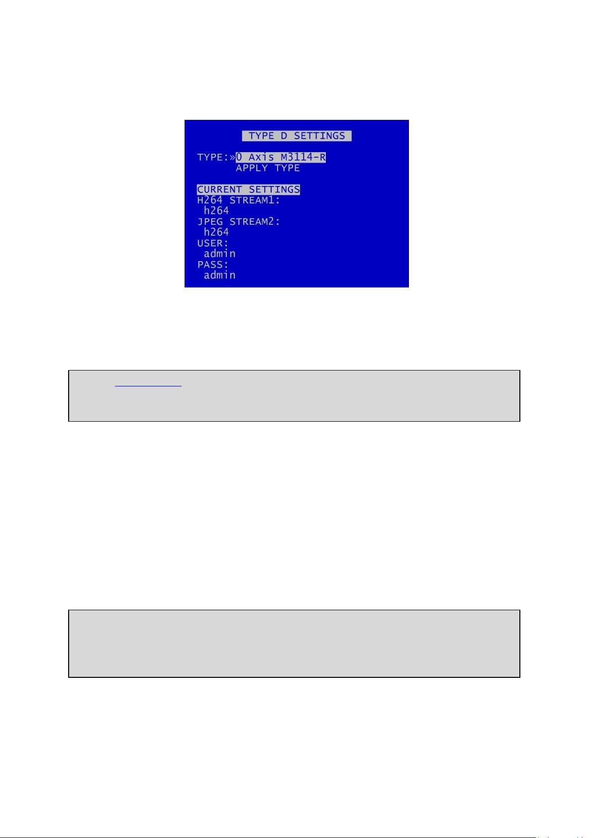
3.1.4.3 Type Settings
The IP Camera “type” allows quick configuration of different camera makes/models.
Navigate to MAIN MENU > IP CAMERAS > TYPE SETTINGS to edit the camera TYPE SETTINGS (in the
example above for TYPE D).
3.1.4.3.1 Pre-configured camera settings
TYPE – The DVR is pre-configured with the default settings for a number of different camera types.
Knowing the camera make and model, scroll through the TYPES to check if settings have been preloaded in the Configuration File (often referred to as the TSCONFIG file). If the camera you require is
listed, select the camera and then select APPLY; the defaults for stream, user and password will be
copied to the appropriate menu entries where they can be further edited if necessary.
The master TSCONFIG file will be updated periodically by Timespace, and the updated files will be
part of subsequent Timespace DVR software releases. Users can also add camera details manually
to the TSCONFIG file, as described in the following section.
31
X500 and R500 Instruction Manual Chapter 3 – User Guide – X500/R500 Menu System
3.1.4.3.2 Configuring camera settings manually
If the required camera isn’t listed in TYPE, it will be necessary to enter the full settings manually.
Enter correct information for:
STREAM1 (recommended for H264; used for recording IP Cameras)
STREAM2 (is recommended for MJPEG; (used for live viewing the IP Cameras whilst recording)
USER – enter the username.
PASS – enter the password
Details of default USER name and PASSWORD should be found in the camera manufacturers’ support
documentation.
Information can be entered via the Keyboard. If the stream name is very long it may be easier to use
the Configuration File to enter the information.
3.1.4.3.3 Using the Configuration File
Navigate to the following menu:
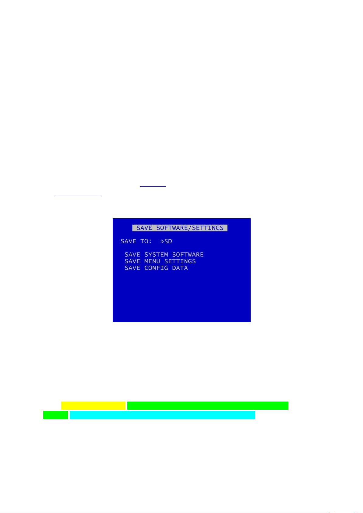
MAIN MENU > SETTINGS MENU > ADVANCED > SAVE SOFTWARE / SETTINGS > SAVE CONFIG DATA
This will save a file onto the hard drive named – TSCONFIG.EXT
This can be opened in a text editor on a PC/laptop (e.g. Notepad) and the stream names etc. typed
in.
Each line is a Camera Type and the syntax is as follows for the example of a Hik camera:
{IPC;3;Hik;DS-2CD2542FWD-IS;Streaming/Channels/101?transportmode=unicast&profile=
Profile_1;Streaming/Channels/102?transportmode=unicast&profile=Profile_1;admin;Password}
Where:
32

X500 and R500 Instruction Manual Chapter 3 – User Guide – X500/R500 Menu System
NB: Available camera options will be updated by Timespace and included in subsequent software
releases. Users can also obtain a current list of cameras by contacting Timespace at
support@tspace.co.uk. The update will be provided as a TCONFIG file which can be uploaded
using the LOAD SOFTWARE/SETTINGS option in the ADVANCED MENU.
Hik;DS-2CD2542FWD-IS – Is the Make and Model of the camera that appears in the TYPE
field of the Type Settings.
Streaming/Channels/101?transportmode=unicast&profile= Profile_1 - Is the name of the
Main Stream.
Streaming/Channels/102?transportmode=unicast&profile=Profile_1 - Is the name of the Sub
Stream.
admin – Is the Username of the Camera.
Password – Is the Password of the Camera.
Each section should be separated by semi-colons.
Save the configuration file and then use the following menu option to load it back into the X500:
MAIN MENU > SETTINGS MENU > ADVANCED > LOAD SOFTWARE / SETTINGS > LOAD CONFIG DATA
Your new setting will now be available in the Type Settings.
33

X500 and R500 Instruction Manual Chapter 3 – User Guide – X500/R500 Menu System
3.1.4.4 Keyboard
A keyboard is available to facilitate the text input, eg, for IP camera types, camera streams, camera
text, vehicle ID. Use the Reviewer right navigation button to access the keyboard from the position
where text is to be entered.
Once on the keyboard screen, use the Menu Navigation direction keys on the Reviewer to navigate
the keyboard.
Press ‘0’ to make selections.
Pressing ‘0’ will add the selected character to the text edit at the current position (shown by the
flashing cursor).
Press SAVE to apply changes. The edited text must be saved before exiting the menu or any changes
will be discarded.
If the text edit is longer than the display area, then the icon <> will be displayed to indicate that the
text is scrollable.
NB: a space character exists on the abc/ABC keyboards.
Select abc/ABC/!@# to toggle the keyboard mode.
Select INSERT to right-shift the text at the current position and enter a space. Note: the character at
the end of the text will be discarded if the maximum length has been reached.
Select DELETE to delete the current highlighted character.
Select CLEAR to clear the text edit.
Select COPY to copy the text edit to the clipboard.
34

X500 and R500 Instruction Manual Chapter 3 – User Guide – X500/R500 Menu System
Select PASTE to paste the clipboard text to the edit. The clipboard text can be copied from one menu
item and pasted to another. Note: the pasted text will be truncated or space-padded to fit within the
bounds of the text edit.
35

X500 and R500 Instruction Manual Chapter 3 – User Guide – X500/R500 Menu System
NB: the local IP address cannot be changed while recording is in progress – an “IP CAMERA
WARNING” will be displayed. Stop recording, and amend the IP address as required before
recommencing recording.
3.1.4.5 Setting the DVR’s Local IP address
LOCAL IP ADDRESS – the LOCAL IP ADDRESS and the CAM IP ADDRESSES must be configured for the
same network. The LOCAL IP ADDRESS for the IP CAMERAS is in the VLAN 2 menu (SETTINGS >
EXTERNAL EQUIPMENT > VLAN2).
36

X500 and R500 Instruction Manual Chapter 3 – User Guide – X500/R500 Menu System
3.1.4.6 Configuring the VLAN Scheme
Navigate to the VLAN Menu (SETTINGS MENU > EXTERNAL EQUIPMENT > VLAN > VLAN SCHEME).
The physical ports for the four IP CAMERAS can be separated from the COMMS physical port by
means of a tag-based VLAN.
The VLAN scheme can be ENABLED or DISABLED as follows:
VLAN SCHEME - ENABLED
When the VLAN SCHEME is ENABLED, the COMMS port is segregated from the IP CAMS ports. The
COMMS port can then be used for remote access (such as FTP/Telnet transfers).
The IP CAMS ports can then be used to connect up to 4 IP cameras for recording.
Please Note: The COMMS port is not intended for use with an IP camera.
VLAN SCHEME - DISABLED
When the VLAN scheme is DISABLED, the COMMS port can be used to access the IP CAMERAS
connected to ports IP CAMS 1-4.
Typically usage is for configuration of the IP cameras via a laptop
NB: Default configuration is with the VLAN scheme ENABLED.
VLAN IP Address
With the VLAN scheme ENABLED, the IP address of VLAN1 (COMMS) can be set to any IP address
desired.
With the VLAN scheme DISABLED, in order to access the IP cameras for configuration, both the
VLAN1 (COMMS) and the VLAN2 (IP CAMERAS) IP addresses must be set to the same range (e.g. the
first 3 octets of the IP addresses must match).
37

X500 and R500 Instruction Manual Chapter 3 – User Guide – X500/R500 Menu System
NB: it is necessary to ‘APPLY IP SETTINGS ABOVE’ or they will be lost upon exit of the menu.
38

X500 and R500 Instruction Manual Chapter 3 – User Guide – X500/R500 Menu System
NB: Camera type: only analogue (SD) cameras can be recorded onto the SD card.
NB: There are some limitations on the use of the SD card for back-up recording if the DVR is also
configured for Motion Detection – this is due to recording resource limitations.
If the DVR is configured for Motion Detection on IP cameras, it is not possible to record any
cameras (either analogue (SD) or IP) to the back-up SD card. A warning banner will be displayed:
3.1.5 SD Recording
The DVR supports a single SD card for two functions;
RECORDING - The DVR can be configured to record up to 25 images per second to the SD card in
addition to the primary recording to the hard disk cartridge (30IPS if in NTSC mode, see VIDEO
SETTINGS). All additional data, for example Audio and GPS, are also included within the SD recorded
files.
FILE COPY - Files that are recorded on the DVR cartridge can be selected and copied to the SD card
for review on a PC.
The SD Card menu shows the current Status of the SD card i.e. PRESENT, NOT PRESENT, LOCKED or
RECORDING TO SD.
39

X500 and R500 Instruction Manual Chapter 3 – User Guide – X500/R500 Menu System
RECORDING ENABLE lists the available modes of recording for the SD card.
OFF – SD recording is OFF, no SD recording.
ON – SD recording onto SD card all the time.
IF NORMAL REC – SD recording only occurs if the DVR is recording in Normal mode.
IF TIMER REC – SD recording only occurs if the DVR is recording in Timer mode.
IF ALARM REC – SD recording only occurs if the DVR is recording in Alarm mode.
LOCK OVERRIDE options OFF or ON can be used to override the physical lock status of the SD card.
For example if an SD card is inserted with the lock enabled, this usually prevents any data being
written, however the DVR can override this.
HDD FAIL SD REC sets the number of seconds that the DVR will continue to record to the SD card
when a FAIL to write to the hard disk drive (HDD) is detected. Available values are 4SECS, 6, 10, 20,
40SECS, 1MIN, 2, 5MINS. After the configured time has elapsed, the DVR will reboot in an attempt to
continue writing to the HDD after boot up. If the HDD fails due to a crash the SD will carry on
recording for the selected period so that the crash events are stored.
RECORDING menu configures the SD card recording setup.
RECORDED FILES menu displays a list of the files on the SD card.
FILE COPY menu is used when copying files from the DVR cartridge to the SD card.
FILE SYSTEM menu configures options for recording on the SD card.
INFO page includes details such as; Size, % used, SD serial number etc.
RESET gives options for deleting files on the SD card .
40

X500 and R500 Instruction Manual Chapter 3 – User Guide – X500/R500 Menu System
NB: A maximum of 25 IPS is available for SD card recording. If the user attempts to configure SD
recording for a higher than this, eg for 4 cameras at 7 IPS each, the DVR will limit the allocation to
a value close to but below the maximum of 25 IPS – eg 3 cameras at 7 IPS each. The user can
then adjust the allocation for each camera as preferred.
3.1.5.1 SD Card Recording
SD CARD RECORDING menu - The DVR can be configured to record up to 25 images per second (IPS)
to the SD card in addition to the primary images per second being recorded to the cartridge. All
additional data e.g. audio and GPS are also included within the SD recorded files.
Images per second and Resolution can be set independently, per channel, from the DVR’s primary
mode of recording e.g. if the DVR is Normal Recording with a QUAL of SUPER, the SD recording files
could be set to MED.
For details of resolution quality options see the section on NORMAL RECORDING.
TOTAL IPS – provides details of current IPS allocation within SD CARD RECORDING, as well as the total
IPS available for SD CARD RECORDING.
HELP – provides details of recording RESOURCE ALLOCATION across the various functions.
41

X500 and R500 Instruction Manual Chapter 3 – User Guide – X500/R500 Menu System
HINT: Files can be write-protected by scrolling down to the file and pressing the left arrow key on
the Reviewer, a W should appear next to the file. Pressing left again will remove the writeprotect.
3.1.5.2 SD Card Recorded Files
The SD CARD RECORDED FILES menu lists the files recorded on the SD card.
The files cannot be played back on the DVR, and must be viewed through PCLink. Navigation of the
file list pages are via the left/right arrow menu keys on the Reviewer when PAGE or FIRST/LAST page
is highlighted.
42

X500 and R500 Instruction Manual Chapter 3 – User Guide – X500/R500 Menu System
WARNING: If other Menu buttons are pressed during the FILE COPY, the action will be aborted.
It is necessary to allow the FILE COPY to finish before attempting any other Menu/programming
options.
A message will be displayed on the SD CARD FILE COPY menu screen when the FILE COPY is
complete.
3.1.5.3 SD Card File Copy
SD CARD FILE COPY is used to copy recorded files from the DVR cartridge to the SD card. A link to the
main cartridge HDD files give quick access to see what is on the cartridge. Some SD statistics are
given to aid in the select process e.g. size and capacity used.
Use HDD RECORDED FILES to view the files on the hard disk.
COPY HDD FILES TO SD CARD by entering the start/end date & time of the period you wish to copy
and then move the cursor down to select COPY FILES.
If there is enough free capacity on the SD card, the copy will begin. Progress of the copy will be
displayed as a percentage and incremental file count as each file is copied.
If the period requested spans multiple files, all files are copied to the SD card for that period. Files are
not cut / clipped. In the following example, all four files would be copied, even though files 1 & 4 only
include a portion of the period requested;
43

X500 and R500 Instruction Manual Chapter 3 – User Guide – X500/R500 Menu System
44

X500 and R500 Instruction Manual Chapter 3 – User Guide – X500/R500 Menu System
3.1.5.4 SD Card File System
SD CARD FILE SYSTEM menu configures options for recording on the SD card.
RECORDING MODE can be set to LOOP RECORD (oldest files will be overwritten first when the SD
card is full); or SINGLE PASS recording (recording will stop when the SD card is full).
FILE LENGTH controls how often a new file is created. A new file is created each time recording
starts. The file will be named with the date/time when the recording started. The next file will be
started as per the file length settings or when next time boundary is met.
File length options are 1MINUTE, 5MINUTES, 10MINUTES, 1HOUR. For further details refer to FILE
SYSTEM menu for the main hard disk cartridge.
FILENAME TEXT - prefixes the recording files with user-defined characters . Characters can be
entered using the Text and Number Input keys on the Reviewer.
FILE SECURITY SETTINGS – configures options for file passwords and encryption
FILE SYSTEM CHECK MENU configures system checking and the creation of system logs for SD CARD
RECORDING.
45

X500 and R500 Instruction Manual Chapter 3 – User Guide – X500/R500 Menu System
3.1.5.5 File Security Settings
File security passwords and encryption can be set for files recorded on the SD card in the same way
as for files recorded on the HDD.
See SETTINGS > SYSTEM SETTINGS > FILE SYSTEM > FILE SECURITY SETTINGS for details.
46

X500 and R500 Instruction Manual Chapter 3 – User Guide – X500/R500 Menu System
NB: No files/data are deleted during the CHECK & CORRECT function.
3.1.5.6 SD Card File System Check
SD CARD FILE SYSTEM CHECK menu configures whether the file system is checked and/or corrected
at power-up and whether a system log is created.
ON POWER SWITCH ON – options are NO CHECK, QUICK CHECK AND CORRECT, FULL CHECK AND
CORRECT.
ON POWER SWITCH OFF – NO CHECK, QUICK CHECK AND CORRECT, FULL CHECK AND CORRECT.
PERFORM CHECK ONLY NOW – will check the files and file system and report any errors but will not
attempt to fix anything.
PERFORM CHECK & CORRECT NOW – will perform a file and file system check and fix any errors that
are found. It also rewrites the FAT and BOOT sectors.
47

X500 and R500 Instruction Manual Chapter 3 – User Guide – X500/R500 Menu System
3.1.5.7 SD Card Info
SD CARD INFO menu provides information about the use of the SD card:
Size in Gigabytes
Gigabytes used
Write protection status
Files
Start date
End date
Days Recording
Card Manufacturer ID
Card Name
Card Serial Number
48

X500 and R500 Instruction Manual Chapter 3 – User Guide – X500/R500 Menu System
3.1.5.8 SD Card Reset
SD CARD RESET gives 2 options for deleting files:
DELETE ALL RECORDING FILES
SECURE CARD WIPE
49

X500 and R500 Instruction Manual Chapter 3 – User Guide – X500/R500 Menu System
WARNING: THERE IS NO “UNDO” OPTION. SELECTING “DELETE ALL FILES ON SD CARD” WILL
ERASE THE DIRECTORY ON THE SD CARD.
3.1.5.9 Delete All SD Recording Files
DELETE ALL SD RECORDING FILES will erase the directory of files from the SD card, including writeprotected files. Only do this if you want to erase all recordings – there is NO undo option*.
Press the right menu button to go to a warning screening, press right again to carry out this action.
Pressing Menu Exit on the Reviewer will abort this procedure.
*in some circumstances Timespace may be able to recover some file data from the disk, but this is not always possible, and
is therefore not to be relied upon.
50
X500 and R500 Instruction Manual Chapter 3 – User Guide – X500/R500 Menu System
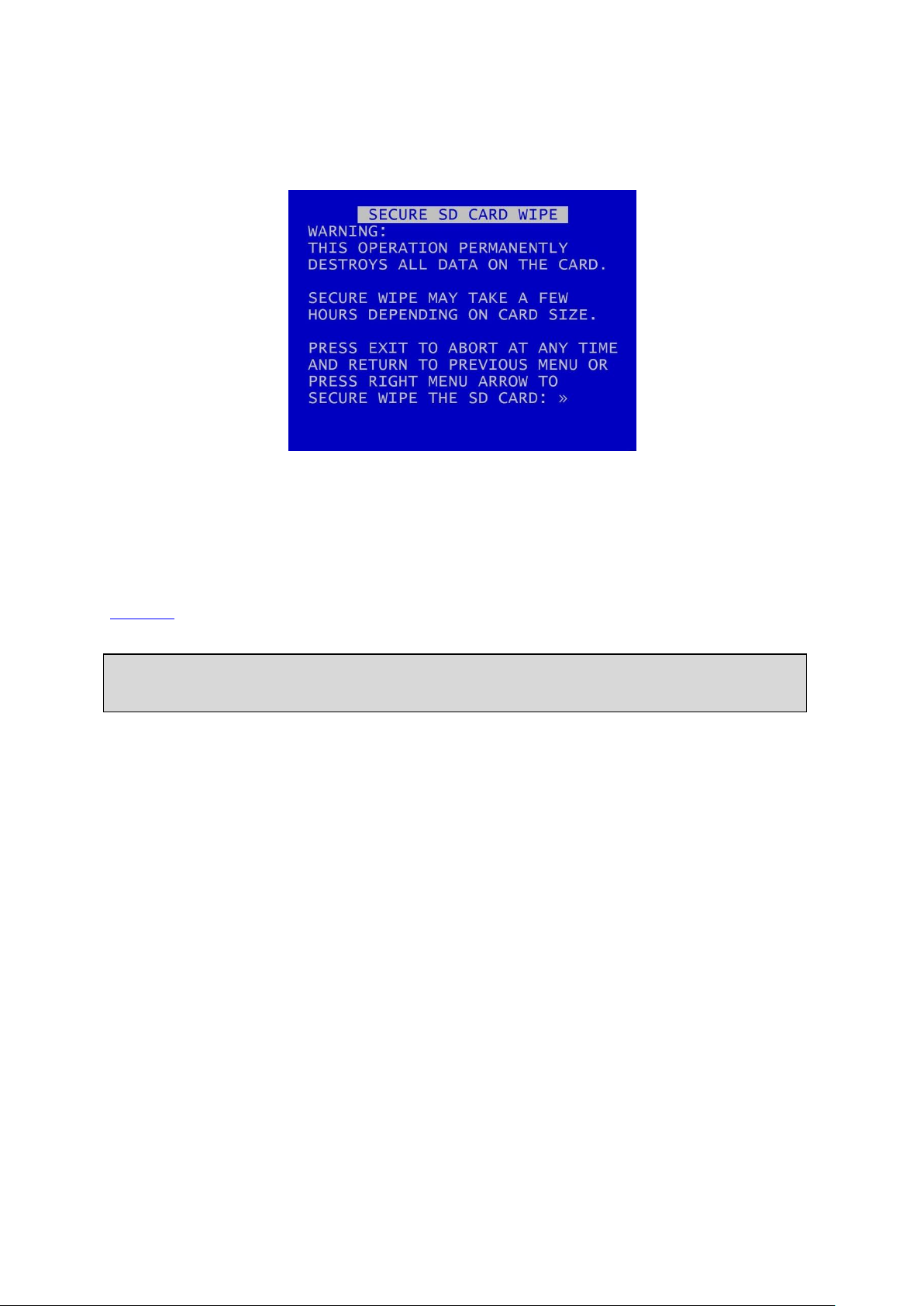
WARNING: THERE IS NO “UNDO” OPTION. SELECTING “SECURE WIPE THE SD CARD” WILL
COMPLETELY REMOVE ALL RECORDINGS ON THE SD CARD.
3.1.5.10 Secure SD Card Wipe
SECURE SD CARD WIPE will permanently delete all recording files on the SD card. This should only be
used if files need to be completely destroyed – the actual file data is deleted, and no recovery by
Timespace is possible.
A final warning message will appear before this function is carried out. Pressing Menu Exit on the
Reviewer will abort.
51

X500 and R500 Instruction Manual Chapter 3 – User Guide – X500/R500 Menu System
NB: Motion Detection is available on the X500 DVR. The R500 DVR does not support Motion
Detection.
Motion Detection Functionality
If Motion Detection is required, this is only available on either analogue (SD) cameras or IP
cameras. The X500 does not provide simultaneous motion detection on both analogue (SD) and
IP cameras.
If Motion Detection is required, other recording is only possible on the same type of camera. For
example, if Motion Detection is configured for IP cameras on NORMAL RECORDING, it will not be
possible to record analogue (SD) cameras on NORMAL RECORDING at the same time. This also
applies for TIMER and ALARM RECORDING settings.
If the X500 is configured for Motion Detection on IP cameras, it is not possible to record any
cameras to the back-up SD card.
3.1.6 Motion Detection – X500 only
3.1.6.1 Understanding Motion Detection functionality
The X500 is a hybrid recorder which supports both analogue (SD) and IP cameras. However, if the
X500 is configured to Motion Detect, this places some limitations on available functions. This is due
to the way the data is processed, and the processing resource required:
52

X500 and R500 Instruction Manual Chapter 3 – User Guide – X500/R500 Menu System
If the user attempts to configure any settings which are outside of the possible Motion Detection
functionality, the following warning screens will be displayed:
53

X500 and R500 Instruction Manual Chapter 3 – User Guide – X500/R500 Menu System
Motion Detection Quick Set-up:
1.
Select the camera(s) you wish to monitor. Set these to ON in the MOTION DETECTION
CAMERA SETUP menu.
2.
Also in the CAMERA SETUP menu, set the camera(s) sensitivity using PERCENTAGE and
DURATION.
3.
In the MASK VIEW/EDIT menu, move/size the cursor box to select the area(s) to be
monitored.
4.
Select the recording mode you wish to trigger, ie NORMAL, TIMER or ALARM in the MOTION
DETECTION menu.
5.
Press record.
NB: Motion Detection is used as a trigger to start one of the recording modes; it is not a recording
mode on its own.
3.1.6.2 Configuring Motion Detection
Motion Detection is used to monitor defined areas for levels of motion above a defined threshold
and then to trigger the DVR recording modes: NORMAL, TIMER or ALARM RECORDING.
Motion Detection is set up by using the MASK/EDIT tool to specify areas of each camera’s view which
are to be monitored for motion, and selecting the level and duration of change which must occur to
produce a motion event.
When MOTION DETECTION is set up, the RECORD LED on the Reviewer will flash on and off. When
motion is triggered, the LED will remain on (solid) for the duration of motion (plus any configured
post-trigger time), then return to flashing.
See the following pages for more detailed instructions for MOTION DETECTION CAMERA SETUP and
using the MASK VIEW/EDIT function.
ARMING DELAY - is typically used to allow the operator to exit a monitored area without triggering
motion detection. Available values are OFF, 5SECS, 10SECS, 30SECS, 1MIN, 2MINS, 5MINS.
POST TRIGGER RECORDING – specifies the duration of recording after motion has ended; select
values between 1 second – 2hours.
PRE-MOTION RATE RECORDING – configures the recording settings in advance of any motion-
triggered recording.
SMTP MESSAGE - If motion is detected, send an SMTP Email with a camera snapshot image as per
settings in the SMTP EMAIL menu in EXTERNAL EQUIPMENT.
When in detect mode, the RECORD LED will flash on and off. When motion is triggered, the LED will
remain solid for the duration of motion plus post trigger time, then return to flashing.
54

X500 and R500 Instruction Manual Chapter 3 – User Guide – X500/R500 Menu System
NOTE: Users will need to define the PERCENTAGE and DURATION as required in each individual
case. The BAR GRAPH tool can assist in determining the required PERCENTAGE – see following
pages.
3.1.6.3 Motion Detection Camera Setup
CAMERA SETUP allows a selection of cameras to be monitored by the motion detection system.
Cameras that are OFF are ignored by motion detection.
PERCENTAGE is used to set the level of change that must occur between successive frames to
produce a motion event.
DURATION is the time period for which consecutive motion events must occur to trigger the motion
system.
If any individual camera is set to OFF in the CAMERA SETUP, it will not be controlled by MOTION
DETECTION even if the record mode is set to YES within the MOTION DETECTION menu.
Example, if:
NORMAL RECORDING is set to record on cameras 1 – 4
NORMAL RECORDING is set to YES in MOTION DETECT MENU
Cameras 1 & 2 are set to YES in MOTION DETECT CAMERA SETUP
Cameras 3 & 4 are set to NO in MOTION DETECT CAMERA SETUP
then; normal recording will be constant on cameras 3 & 4. Cameras 1 & 2 will only record when
motion detection is triggered (for the duration of motion plus the post-trigger time).
55

X500 and R500 Instruction Manual Chapter 3 – User Guide – X500/R500 Menu System
Menu keys to move / size the box cursor:
Play key
increase box width
Fast Forward key
increase box height
Back key
decrease box width
Rewind key
decrease box height
When the GREEN box is shown:
0 key =
activate/include area (camera view is clear).
When the RED box is shown:
0 key =
deactivate/exclude area (camera view is greyed out).
Multiple areas can be defined.
Excluded areas will be greyed out.
NB: Any areas set to be included/excluded will be saved to the X500 and maintained, even after a
reboot.
3.1.6.4 Mask View/Edit
MASK VIEW/EDIT allows the user to define the area of each camera to be monitored for motion
detection. This is done using a moveable and variable size box cursor.
The box cursor is moved and resized using controls on the Reviewer.
By default, when a camera view is first selected, the entire view is activated and is therefore included
in motion detection.
The STOP key is used to switch the select box between GREEN, RED and BAR GRAPH modes.
56

X500 and R500 Instruction Manual Chapter 3 – User Guide – X500/R500 Menu System
When the BAR GRAPH is shown:
0 key =
reset red maximum marker to zero
Up/Down
increase/decrease PERCENTAGE
3.1.6.5 Bar Graph Tool
The BAR GRAPH tool assists the user in determining the PERCENTAGE and DURATION settings. It is
useful to test the active and inactive areas for motion detection when setting these up on a
Reviewer.
As the marker on the BAR GRAPH is moved, the corresponding percentage for the relevant camera
view will change on the MOTION DETECTION CAMERA SETUP page.
57
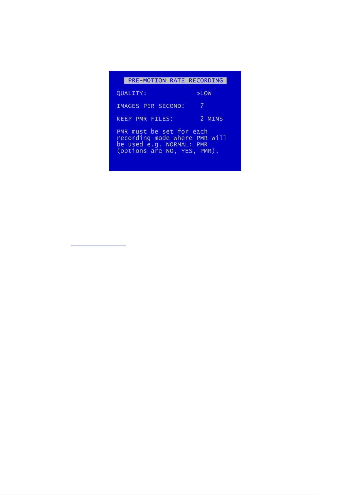
X500 and R500 Instruction Manual Chapter 3 – User Guide – X500/R500 Menu System
3.1.6.6 Pre-Motion Rate Recording
PRE-MOTION RECORDING (PMR) - Pre motion recording feature enables a user to configure the DVR
to record files at a lower IPS Rate and Quality during non motion periods, then increase the IPS when
recording is triggered by motion. In this instance, a file may consist of low IPS, then higher IPS, then
low IPS footage as the motion trigger is set on/off.
When PMR is active, the RECORD LED will be on continuously.
Within the MOTION DETECTION menu, PMR must be set for each recording mode where PMR will be
used e.g. NORMAL:PMR (options are NO, YES, PMR). DVR recording priorities still apply i.e. Alarm
takes over from Normal, even when motion or PMR is set.
58

X500 and R500 Instruction Manual Chapter 3 – User Guide – X500/R500 Menu System
X500 Audio Recording
R500 Audio Recording
3.1.7 Audio Recording
This menu allows configuration of the audio recording parameters. Audio can be enabled or disabled
(ON / OFF) for the following recording types; Normal, Timer Alarm and SD Recording.
The X500 and R500 DVRs have different Audio provisions so are dealt with separately in the following
sections.
59

X500 and R500 Instruction Manual Chapter 3 – User Guide – X500/R500 Menu System
3.1.8 X500 Audio
The X500 provides one STANDARD QUALITY AUDIO input and 4 HIGH QUALITY AUDIO inputs (see
Figure 10 - X500 Connections/Wiring).
Audio can be enabled or disabled (ON / OFF) for NORMAL RECORDING, TIMER RECORDING, ALARM
RECORDING and SD CARD RECORDING.
NB: The X500 inputs are mic-level therefore no preamplifier is required, as the DVR amplifies the
signal.
60

X500 and R500 Instruction Manual Chapter 3 – User Guide – X500/R500 Menu System
3.1.8.1 Standard Quality Audio
The STANDARD QUALITY AUDIO menu allows the configuration of the audio recording parameters
for the one Standard Quality Audio input on the X500.
MIC INPUT – select ON/OFF
SAMPLING RATE – can be set to kHz RATES; 8, 16, 32, 44.1kHz (CD quality) and 48 kHz. Changing the
RATE will affect the X500 recording time before the cartridge loops and begins overwriting the oldest
footage.
SAMPLING RESOLUTION – fixed at 16bits.
AUDIO IN SENSITIVITY – The X500 is configurable so that the input range can be set from 0.002 -
2.0Vrms (sensitivity).
AUDIO ADVANCED – configures settings for audio testing.
TEST AUDIO IN FILES – allows the user to play recorded files with just the audio so as to test the
audio function. No video will play during the audio test.
61

X500 and R500 Instruction Manual Chapter 3 – User Guide – X500/R500 Menu System
NB: Standard Quality Audio playback from the DVR via the Reviewer is only available for test
purposes.
To listen to audio from recorded video footage, recorded files must be played back via PCLink.
For full details on Audio playback via PCLink, consult the PCLink manual at www.tspace.co.uk .
3.1.8.2 Audio Advanced (Standard Quality Audio)
TEST MENU – gives options for testing the Audio function.
Playback via the Reviewer is in mono via channel 1 only (Left). Playback volume of the Reviewer's
built in speaker can be adjusted between; MUTE, LOW, MEDIUM, HIGH, FULL.
AUDIO IN SENSITIVITY – the X500 is configurable so that the input range can be set from 0.002 -
2.0Vrms (sensitivity).
MIC LEVEL – when recording, input levels will be shown as NOT RECORDING or as a percentage so
the X500 can be setup to avoid distortion. The sensitivity configuration will be dependent on the
environment of the installation.
62

X500 and R500 Instruction Manual Chapter 3 – User Guide – X500/R500 Menu System
NB: this Audio test function is available only for the Standard Quality Audio. For information on
testing High Quality Audio, see the HIGH QUALITY AUDIO section.
3.1.8.3 Audio Test Menu
The AUDIO TEST MENU sets the parameters for carrying out an audio test.
TEST WAVE – for Timespace test purposes only.
TEST DURATION – select 1 SEC, 2, 3, 4, 5,10, 20, 30, 40, 50, 60 SECS, PERPETUAL.
HPOUT LOOPBACK (for X500 Standard Quality Audio and R500 only) – can be selected to OFF/ON.
This provides high power output for listening to live audio being recorded using the speaker on the
Reviewer.
63

X500 and R500 Instruction Manual Chapter 3 – User Guide – X500/R500 Menu System
Testing the High Quality Audio:
Microphones – to check that microphones are functioning, use headphones and a lead connected
to the Audio Out connector (Figure 9 - X500 Rear Interface).
Audio in recorded files – to check that audio has recorded along with video in files, view a file in
PCLink software
3.1.8.4 High Quality Audio
The HIGH QUALITY AUDIO menu allows configuration of the audio recording parameters for the four
High Quality Audio inputs on the X500.
INPUTS 1 – 4 – select ON/OFF
SAMPLING RATE is fixed at 48.0kHz and SAMPLING RESOLUTION is fixed at 24 bits.
AUDIO OUT GAIN – the audio out gain can be adjusted as required; select a value from -96 to +96dB.
.
64
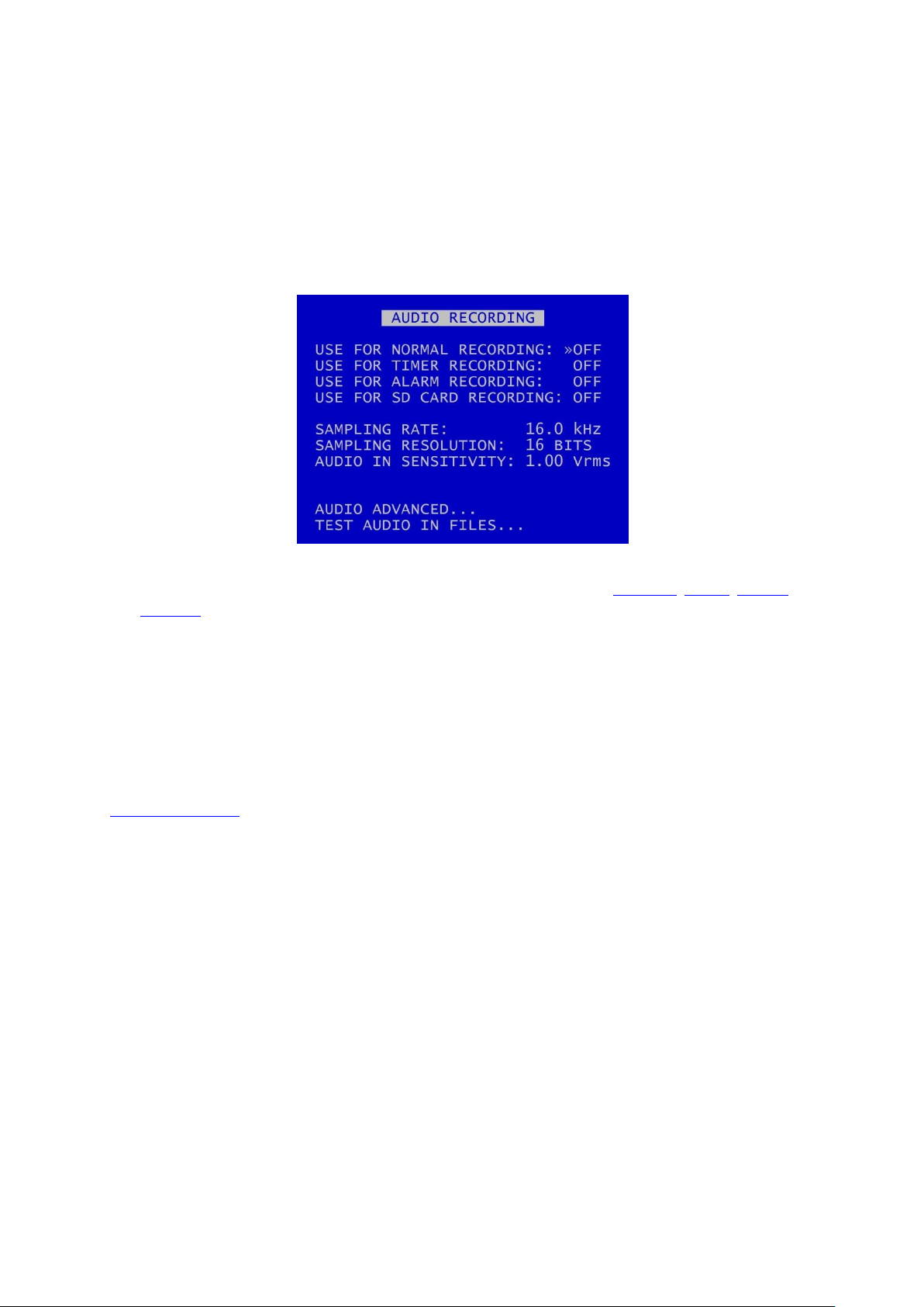
X500 and R500 Instruction Manual Chapter 3 – User Guide – X500/R500 Menu System
3.1.8.5 R500 Audio
The R500 has one standard quality audio input (see Figure 12 - R500 Connections/Wiring)
NB: The X500 inputs are mic-level therefore no preamplifier is required, as the DVR amplifies the
signal.
AUDIO RECORDING menu allows configuration of the audio recording parameters on the R500. Audio
can be enabled or disabled (ON / OFF) for the following recording types; NORMAL, TIMER, ALARM
and SD CARD.
SAMPLING RATE can be set to 8kHz, 16, 32, 44.1 or 48kHz.
SAMPLING RESOLUTION is set to 16BITS, giving CD-quality audio recording.
AUDIO IN SENSITIVITY – The R500 is configurable so that the line-level input range can be set from
0.002 - 2.0Vrms (sensitivity).
AUDIO ADVANCED – configures settings for Audio testing.
TEST AUDIO IN FILES – allows the user to play files with just the audio so as to test the audio function.
No video will play during the audio test.
65
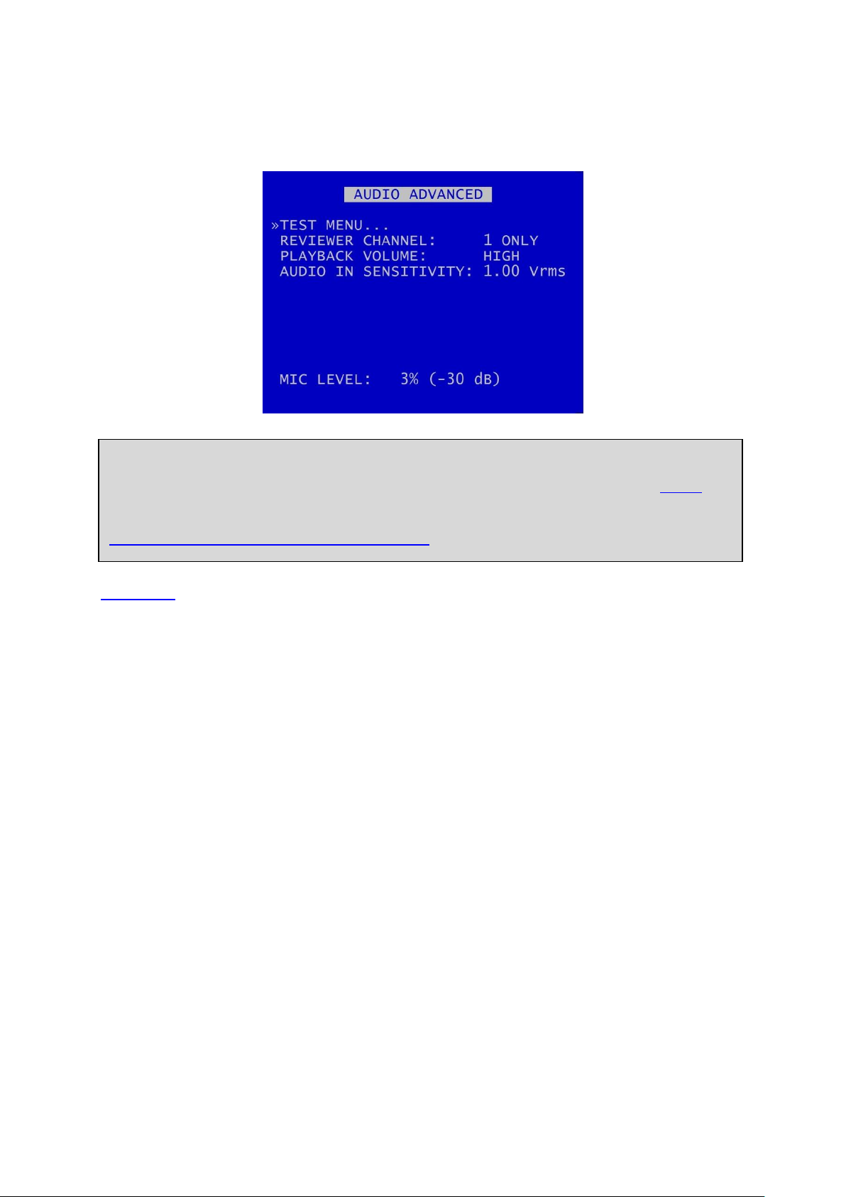
X500 and R500 Instruction Manual Chapter 3 – User Guide – X500/R500 Menu System
NB: Audio playback from the R500 via the Reviewer is currently only available for test purposes.
To listen to audio from recorded video footage, recorded files must be played back via PCLink.
For full details on Audio playback via PCLink, consult the PCLink manual at
https://www.tspace.co.uk/pdf/pclink%20suite.pdf.
3.1.8.6 Audio Advanced (R500)
TEST MENU – provides options for testing the Audio function.
Playback via the Reviewer is in mono via channel 1 only (Left). Playback volume of the Reviewer's
built in speaker can be adjusted between; MUTE, LOW, MEDIUM, HIGH, FULL.
AUDIO IN SENSITIVITY – the R500 is configurable so that the input range can be set from 0.002 -
2.0Vrms (sensitivity).
MIC LEVEL – when recording, input levels will be shown as NOT RECORDING or as a percentage so
the R500 can be setup to avoid distortion. The sensitivity configuration will be dependent on the
environment of the installation.
66
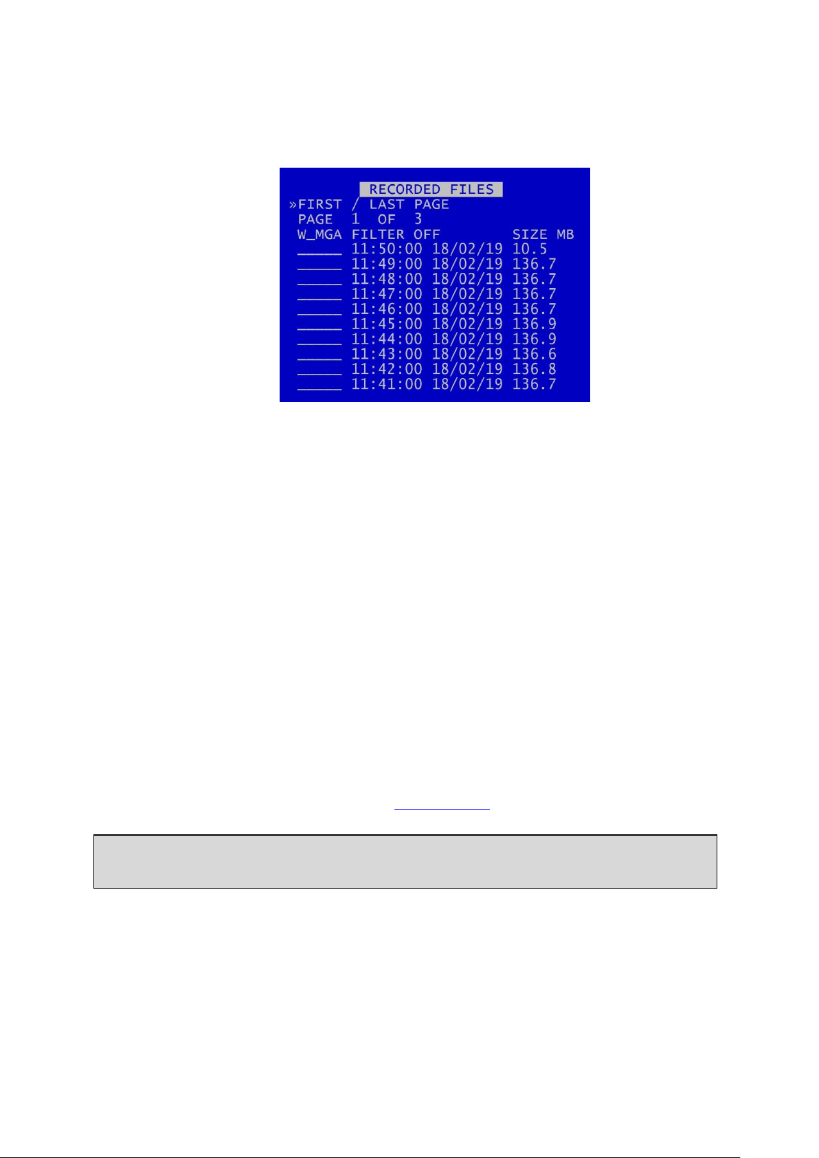
X500 and R500 Instruction Manual Chapter 3 – User Guide – X500/R500 Menu System
HINT: The W status can be added or removed by pressing the Left Menu Navigation key when the
cursor is next to the recorded file.
3.1.9 Recorded Files
RECORDED FILES menu lists the recorded files on the HDD (most recent first) and allows the user to
select a file to play or to change the write-protect status of a file.
Files are shown in chronological order, most recent file first. Files are displayed by;
HH:MM:SS DD/MM/YY SIZE MB
File status indicators include;
W - Write protected
A - Alarm
M - Motion detection
P - Motion detection (pre trig)
G - GSensor
K - Alarm PAR Keep
A file may have multiple statuses. For example, a write protected alarm file that was triggered by
motion could have A W M indicators.
A file with a W status will not be overwritten on Loop Recording.
67

X500 and R500 Instruction Manual Chapter 3 – User Guide – X500/R500 Menu System
HINT: To higlight a file status indicator, use the right arrow key to scroll through W, M, G, A. The
selected letter will have a white background, and a message “FILTER ON” will be displayed.
Continuing to scroll with the right arrow button will take the selection back to “FILTER OFF”.
Navigation is using the Menu Navigation keys on the Reviewer as follows:
FIRST / LAST PAGE – Left key = go to last page; Right key = go to first page
PAGE – Left key = go to next page; Right key = go to previous page
Up/Down keys - move cursor to a file
When a file is selected, Right key = play file
FILTER ON/OFF - The recorded files list can be quickly filtered in order to display only a certain file
type e.g. only those that are Alarm files.
By highlighting the letter (file status indicator), RECORDED FILES will be filtered by that status, e.g.
show all Write-protected files, all GSensor Alarm files or all Alarm Recording files..
68

X500 and R500 Instruction Manual Chapter 3 – User Guide – X500/R500 Menu System
X500 Video Output
R500 Video Output
3.1.10 Video Output
VIDEO OUTPUT menu controls the automatic switching and dwell time of cameras on the various
video outputs:
MAIN VIDEO SWITCHER – controls automatic switching and dwell time of analogue (SD) cameras (1-
4)on the Main Switcher (main video out).
AUX VIDEO SWITCHER – controls automatic switching and dwell time of analogue (SD) cameras on
the auxiliary (secondary) video output (X500 only; not available on the R500).
RTSP VIDEO SWITCHER – RTSP is offered as standard on the X500. RTSP is offered as an option on
the R500; contact Timespace for more details.
When in Auto mode (selected by pressing the Auto key on the Reviewer), the video output will
switch between the configured cameras for the set period of time.
Single camera output is selected by pressing the camera number on the Reviewer.
69

X500 and R500 Instruction Manual Chapter 3 – User Guide – X500/R500 Menu System
NB: Switchers can show analogue (SD) cameras only.
3.1.10.1 Main Video Switcher
MAIN VIDEO SWITCHER menu controls automatic switching and dwell time of cameras on the Main
Switcher (main video out).
When in AUTO mode (selected by pressing the AUTO key on the Reviewer), the video output will
switch between the configured cameras for the set period of time.
CAM/SEC – Set the desired camera DWELL time (in seconds) next to each camera that is to be
included in the switcher sequence (1-30 SECONDS).
DIGITAL SWITCHING OPTIONS – configures the use of the digital switcher on the MAIN video output.
MULTI CAMERA (SEC) – Set the number of seconds for which the MULTI CAMERA view is displayed.
Available options are: 1 SEC, 2, 3, 4, 5, 10, 20, 30SECS,
MULTI MENU – configures which cameras are to be displayed simultaneously on the MULTI CAMERA
view. The output is split into tiles per camera. MULTI CAMERA can be included in the Auto switching
sequence.
70

X500 and R500 Instruction Manual Chapter 3 – User Guide – X500/R500 Menu System
NB: Time/date information and recording status can not be shown on the switcher without use of
DIGITAL SWITCHING, i.e. if live analogue images are used as the video source.
NB: X500 only - Digital switching priorities – selecting DIGITAL SWITCHING on the MAIN
SWITCHER will prevent use of the Multi-Camera on the X500 Auxiliary Switcher. This is due to
recording resource limitations.
3.1.10.2 Digital Switching Options
Digital Switching Options menu – configures the use of the digital switcher on the MAIN VIDEO
SWITCHER output.
MAIN USE DIGITAL SWITCHER – select YES/NO
If DIGITAL SWITCHER is not selected, the video source will be the live analogue image from the
selected camera.
When DIGITAL SWITCHING is selected, time/date information and recording status text can be
shown.
TEXT POSITION – select from NO TEXT, BOTTOM HIGH, BOTTOM MIDDLE, BOTTOM LOW, TOP HIGH,
TOP MIDDLE, TOP LOW to display Time/date information in the selected position.
SHOW REC STATUS – select from YES/NO (note that if TEXT POSITION is set to NO TEXT, then SHOW
REC STATUS will be set to default of NO. To enable selection of YES for SHOW REC STATUS, ensure
that one of the BOTTOM or TOP TEXT POSITION options is selected above).
71

X500 and R500 Instruction Manual Chapter 3 – User Guide – X500/R500 Menu System
HINT: Pressing the Auto key on the Reviewer will switch the video output between the configured
cameras for the set period of time. Single camera output is selected by pressing the camera
number on the Reviewer.
3.1.10.3 Multi Menu
MULTI MENU – configures the settings for the MULTI CAMERA setup.
TEXT POSITION – sets the position of the time/date text on the MULTI CAMERA view. Select from NO
TEXT, BOTTOM HIGH, BOTTOM MIDDLE, BOTTOM LOW, TOP HIGH, TOP MIDDLE, TOP LOW.
SHOW REC STATUS – Select YES/NO to determine whether the recording status is shown on the
embedded text in MULTI CAMERA setup.
MULTI CAMERA SETUP - configures which cameras are to be displayed simultaneously in the MULTI
camera view. The output is split into tiles per camera, each tile is a quarter of the MULTI CAM view.
Cameras for each tile are selected using the left/right Menu Navigation keys on the Reviewer to scroll
through the camera number options. Move along/up/down the tiles using the up/down Menu
Navigation keys.
MULTI CAMERA VIEW – provides a “preview” of the multi camera setup.
72

X500 and R500 Instruction Manual Chapter 3 – User Guide – X500/R500 Menu System
NB: Digital switching priorities – selecting DIGITAL SWITCHING on the MAIN SWITCHER will
prevent use of the Multi-Camera on the Auxiliary Switcher. This is due to recording resource
limitations.
3.1.10.4 Aux Video Switcher (X500 only)
X500 Aux Video Switcher
AUX VIDEO SWITCHER configures the settings for the auxiliary (secondary) video output.
AUX VIDEO SWITCHER settings, e.g. for MULTI CAMERA and TIME/DATE POSITION are configured in
the same way as for MAIN VIDEO SWITCHER.
73

X500 and R500 Instruction Manual Chapter 3 – User Guide – X500/R500 Menu System
NB: IP Cameras cannot be streamed over RTSP.
3.1.10.5 RTSP Video Switcher
The Real Time Streaming Protocol (RTSP) is a network protocol allowing video to be streamed to an
RTSP client.
If the DVR has the resources to enable RTSP then the server URL will be displayed, otherwise the
menu will show “RTSP disabled”. See Resource Allocation for further information on recording and
streaming resource requirements.
Individual analogue (SD) cameras can be configured to stream their video for a pre-set time before
switching to the next camera.
CAM / SEC – Select the required dwell time for each camera from 4, 6, 8, 10, 20, 30 SEC.
If in use, the RTSP stream will be shown. Otherwise the RTSP screen will display “RTSP disabled”.
74

X500 and R500 Instruction Manual Chapter 3 – User Guide – X500/R500 Menu System
3.2 Settings Menu
3.2.1 System Settings
The SYSTEM SETTINGS MENU gives access to configure various system settings and to view system
information.
75

X500 and R500 Instruction Manual Chapter 3 – User Guide – X500/R500 Menu System
NB: date and time settings cannot be changed while the unit is recording.
3.2.2 Time and date
TIME AND DATE menu displays the current time/date. New times/dates can be set by entering new
values using keys 0-9 on the Reviewer.
MODE – The date display can be switched between DD/MM/YY and MM/DD/YY. The chosen format
will be used for date entry and display throughout the system.
SET CLOCK TO THESE SETTINGS – confirms and sets the new time/date.
SUMMERTIME ADJUST – can be selected for UK, EUR USA, NZ or OFF. Automatically updates the
system to daylight saving time, valid for the country selected. Adjustments are applied even if the
system was powered off during the time change.
SUMMER/WINTER TIME – displays the current season, dependant on the SUMMERTIME ADJUST
selected above.
When the clock is put forward, the time is now summer time, which is winter time +1 hour. When
the clock is put back, time reverts to winter time.
UK - At 1am on the last Sunday in March, the clock is put forward an hour. At 2am on the last Sunday
in October, the clock is put back and hour.
Central Europe - At 2am on the last Sunday in March, the clock is put forward an hour. At 3am on the
last Sunday in October the clock is put back an hour.
USA - At 2am on the second Sunday in March, the clock is put forward an hour. At 2am on the first
Sunday in November, the clock is put back an hour.
76

X500 and R500 Instruction Manual Chapter 3 – User Guide – X500/R500 Menu System
NB: when time or date are changed, a hard disk re-format is recommended in order to reset the
meta file.
NZ – at 2am on the last Sunday in September, the clock is put forward an hour. At 3am on the first
Sunday in April, the clock is put back an hour.
77

X500 and R500 Instruction Manual Chapter 3 – User Guide – X500/R500 Menu System
3.2.3 Alarm Inputs/Outputs Menu
ALARM INPUTS/OUTPUTS (I/O) menu configures Alarm Recording and INPUT / OUTPUT options.
Alarm Inputs and Outputs can also be configured as per the ALARM INPUTS/OUTPUTS menu in
settings for ALARM RECORDING.
78

X500 and R500 Instruction Manual Chapter 3 – User Guide – X500/R500 Menu System
3.2.4 Camera Settings
CAMERA SETTINGS menu configures the CAMERA TEXT labels, timestamp position, VIDEO SETTINGS
and camera disconnect time.
TIMESTAMP POS - the timestamp can be positioned either below (BOTTOM) or above (TOP) the
main area of the recorded image and fine adjustment of position made with LOW/MIDDLE/HIGH
settings. The timestamp can also be turned off (select NO TIMESTAMP) and will not be written in to
the recorded images.
VIDEO SETTINGS - controls the video standard (PAL or NTSC).
CAMERA DISCONNECT TIME – this option allows disconnected cameras to be reported as connected
for a set time period. This is useful in cases where a camera can take a while to boot and send its
signal. If there is no signal after the timeout, the camera is treated as disconnected and is flagged in
the service log. Available options are OFF, 10SEC, 30SEC, 1MIN, 2MIN, 5MIN.
79

X500 and R500 Instruction Manual Chapter 3 – User Guide – X500/R500 Menu System
3.2.4.1 Camera Text
Individual text for each camera can be inserted above the timestamp. This text, along with
timestamp, will be shown on recorded images.
12 user-defined characters can be input per camera. Enter text using the keyboard.
DUPLICATE TEXT – feature is available for copying down text from camera 1 to all remaining cameras.
80

X500 and R500 Instruction Manual Chapter 3 – User Guide – X500/R500 Menu System
NB: After changing the video standard setting, the unit will automatically reboot after 5 seconds
for the change of setting to take effect. A red “Reboot Required” warning will flash on the screen
before the reboot commences.
3.2.4.2 Video Settings
VIDEO SETTINGS menu controls the video standard, i.e. whether the unit is to operate with PAL or
NTSC cameras.
81

X500 and R500 Instruction Manual Chapter 3 – User Guide – X500/R500 Menu System
NB: File size is limited to 4GB. After this limit is reached, a new file will be created.
3.2.5 File System
FILE SYSTEM MENU Sets the parameters of the file system and how files are laid to disk.
RECORDING MODE sets either:
LOOP RECORD (oldest files will be overwritten first when the hard disk cartridge is full) or
SINGLE PASS recording (recording will stop when the hard disk cartridge is full).
FILE LENGTH – controls how often a new file is created. A new file is created each time recording
starts. The file will be named with the date/time when the recording started. If continuous recording,
the next file will be started as per the file length settings or when next time boundary is met. For
example when using 10min files, if recording starts at 10:03, the first file will contain 7minutes of
video and the second file will be started at 10:10. New files will then be created every 10 minutes,
i.e.10:20, 10:30 etc. Files can be configured for: 1 min, 5 min, 10 min, or 1 hour.
FILENAME TEXT – prefixes the recording files with up to 12 user defined characters (0-9, A-Z, space).
Text and numbers are entered using the Reviewer.
WRITE PROTECT ALARM REC – selects whether alarm recording files are write protected. If alarm files
are write-protected they will not be deleted on LOOP recording. Select YES/NO.
FILE SECURITY SETTINGS – configures options for file password and encryption.
FILE SYSTEM CHECK menu – configures whether the file system is checked (and possibly corrected)
at power up and also if a system log is created.
82

X500 and R500 Instruction Manual Chapter 3 – User Guide – X500/R500 Menu System
NB: any settings configured here on the DVR menu will be over-written by LANLink if LANLink is
managing the security settings for the DVR. See LANLink Manual or contact Timespace for further
details.
3.2.5.1 File Security Settings
This menu provides options for setting file security on the DVR.
Select from the 3 available levels of file protection:
DISABLED – No file protection.
PASSWORD – the files are password protected.
PASS. & ENCRYP. – the files are password protected and the audio and video data in the file is
encrypted.
83

X500 and R500 Instruction Manual Chapter 3 – User Guide – X500/R500 Menu System
NB: the default old password is 0000 (four zeros).
3.2.5.2 Setting a password
A password length from 1 – 14 characters is valid. Timespace recommends a password of 5 or more
characters. All characters that can be entered from the Reviewer are valid:
SET PASSWORD will set the new password and activate the selected File Security Settings.
3.2.5.3 DVR Menu and Playback Protection:
Optionally set a MENU and PLAYBACK Pin can be set (see SETTINGS MENU > SYSTEM SETTINGS >
SYSTEM SECURITY). This prevents unauthorised access to the DVR menu settings, but permits
controlled access eg for engineers in the field to review camera angles on a Reviewer and amend
settings.
84

X500 and R500 Instruction Manual Chapter 3 – User Guide – X500/R500 Menu System
NB: No XBA files/data are deleted during the check and correct function.
3.2.5.4 File System Check
FILE SYSTEM CHECK menu configures whether the file system is checked (and possibly corrected) at
power up and also if a system log is created.
ON POWER SWITCH ON – select from options:
No check / Quick check and correct / Full check and correct
Create system log / do not create system log
ON POWER SWITCH OFF:
No check / Quick check and correct / Full check and correct
PERFORM CHECK ONLY NOW will check the files and file system and report any errors but will not
attempt to fix anything.
PERFORM CHECK AND CORRECT NOW will perform a file and file system check and fix any errors that
are found. It also rewrites the FAT and BOOT sectors.
See also POWER OPTIONS > ADVANCED POWER OPTIONS MENU > ADVANCED IGNITION OFF MENU
for further details of when CHECK AND CORRECT may be aborted due to selection of SHUTDOWN or
STANDBY settings.
85

X500 and R500 Instruction Manual Chapter 3 – User Guide – X500/R500 Menu System
3.2.6 System Info
SYSTEM INFO menu displays information about the system;
OPERATING SYSTEM – Currently installed/running software version.
FIRMWARE – Currently installed/running firmware version (FPGA build / H264 codec / PCB Rev).
SIZE IN GIGABYTES - Total size of installed hard disk cartridge.
USED - Percentage of hard disk cartridge used by any files.
WRITE PROTECTED – Percentage of cartridge used by write protected files.
FILES – Number of XBA files on the hard disk cartridge.
START DATE - The date of the first (oldest) file on the cartridge.
END DATE - The date of the last (newest) file on the cartridge.
DAYS RECORDING - The number of days between the start/end date. NB: there may not be
continuous recording files between the start/end dates.
TEMP – temperature of the unit during operation.
H/W VERSION – hardware version, ie the model number of the DVR unit.
SERIAL NUMBER - Displays the X500 serial number.
86

X500 and R500 Instruction Manual Chapter 3 – User Guide – X500/R500 Menu System
NB: File Security Settings – file access password and encryption protection – are set separately at
SYSTEM SETTINGS > FILE SYSTEM > FILE SECURITY SETTINGS.
3.2.7 System Security
The SYSTEM SECURITY menu sets a password to restrict user access to five key areas of the system. A
read-only access can be set that allows files to be viewed and limited features to be used. For each
area, select YES/NO.
RECORD - If set to YES, the record button on the front panel and the Reviewer are pin code
protected.
MENU - If set to YES, access to the menu system is pin code protected.
SWITCHER - If set to YES, the button to activate auto switcher mode is pin code protected.
PLAY – If set to YES, the controls to review recorded footage are pin code protected.
READ ONLY - If set to YES, the user cannot change any setting on the DVR. The menu system can be
browsed but no settings changed. If a setting change is attempted, the element will flash in RED for 2
seconds and not be changed. To exit read only mode, change read only to NO, at which point you will
be prompted for the pin code.
If access to a pin code protected function is attempted, the user is prompted with the “enter pin
code” screen. On correct pin code entry the pin code protection is temporarily disabled while that
function is being used.
CHANGE SYSTEM PIN – provides options for changing the pin code.
FTP/TELNET USERS – gives options to access the DVR by FTP/Telnet.
87

X500 and R500 Instruction Manual Chapter 3 – User Guide – X500/R500 Menu System
NB: File Security Settings – file access password and encryption protection – are set separately at
SYSTEM SETTINGS > FILE SYSTEM > FILE SECURITY SETTINGS.
NB: the default old pin code is 0000 (four zeros).
3.2.7.1 Change PIN
CHANGE PIN menu provides options for changing the pin code.
The pin code can be changed by first entering the current pin code, followed by the new one
(entered twice for verification). The pin code format is four digits only 0-9. Enter numbers using the
Reviewer.
Set the new PIN by selecting SET PIN.
In the event of a complete password lockout, contact your installer or Timespace for a master unlock
code; email support@tspace.co.uk
88
 Loading...