

TIMES MICROWAVE SYSTEMS
LMR®-240-UF
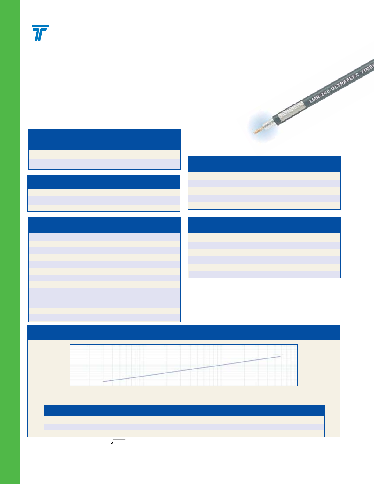
UltraFlex Communications Coax
Ideal for…
•Jumper Assemblies in Wireless Communications Systems
• Short Antenna Feeder runs (e.g. WLL, GPS, LMR,
Mobile Antennas)
•Anyapplicationthatrequiresadditionalexibility
LMR-240-UF
Part Description
Stock
Part Number Application Jacket Color Code
LMR-240-UF Indoor/Outdoor TPE Black 54041
LMR-240-UF-FR Indoor/Outdoor FRPE Black 54143
Environmental Specications
Performance Property
Installation Temperature Range -40/+185 -40/+85
Storage Temperature Range -94/+185 -70/+85
Operating Temperature Range -40/+185 -40/+85
0
F
o
C
Description Material In. (mm)
Inner Conductor Stranded BC 0.056 (1.42)
Dielectric Foam Polyethylene 0.150 (3.81)
Outer Conductor Aluminum Tape 0.155 (3.94)
Overall Braid Tinned Copper 0.178 (4.52)
Jacket (See Table) 0.240 (6.10)
Construction Specications
Electrical Specications
Performance Property Units US (metric)
Velocity of Propagation % 80
Dielectric Constant NA 1.42
Time Delay nS/ft (nS/m) 1.21 (3.97)
Impedance ohms 50
Capacitance pF/ft (pF/m) 24.2 (79.4)
Inductance uH/ft (uH/m) 0.060 (0.20)
Shielding Effectiveness dB >90
DC Resistance
Inner Conductor ohms/1000ft (/km) 4.28 (14.1)
Outer Conductor ohms/1000ft (/km) 3.89 (12.8)
Voltage Withstand Volts DC 1500
Jacket Spark Volts RMS 5000
Peak Power kW 5.6
Attenuation vs. Frequency (typical)
100.0
10.0
Attenuation
(db per 100 feet)
1.0
10 100 1,000 10,000
Frequency (MHz)
Mechanical Specications
Performance Property Units US (metric)
Bend Radius: installation in. (mm) 0.75 (19.1)
Bend Radius: repeated in. (mm) 2.5 (63.5)
Bending Moment ft-lb (N-m) 0.125 (0.17)
Weight lb/ft (kg/m) 0.034 (0.05)
Tensile Strength lb (kg) 80 (36.3)
Flat Plate Crush lb/in. (kg/mm) 13 (0.23)
Frequency (MHz) 30 50 150 220 450 900 1500 1800 2000 2500 5800
Attenuation dB/100 ft 1.6 2.1 3.6 4.4 6.3 9.1 11.8 13.0 13.8 15.5 24.4
Attenuation dB/100 m 5.3 6.8 11.9 14.4 20.8 29.8 38.9 42.8 45.2 50.9 80.1
Avg. Power kW 1.24 0.96 0.55 0.45 0.31 0.22 0.17 0.15 0.14 0.13 0.08
Calculate Attenuation = (0.290501) • FMHz + (0.000396) • FMHz (interactive calculator available at http://www.timesmicrowave.com/cable_calculators)
62
Attenuation: VSWR=1.0; Ambient = +25°C (77°F) Power: VSWR=1.0; Ambient = +40°C; Inner Conductor = 100°C (212°F);
Sea Level; dry air; atmospheric pressure; no solar loading
(800) TMS-COAX • www.timesmicrowave.com

TIMES MICROWAVE SYSTEMS
1.
TC-240-BMC
3190-242
TC-240-NMC
3190-244
9. 10. 11.
TC-240-NMH-RA-D
3190-2426
Connectors
Part Stock VSWR** Coupling Contact Contact Body Length Width Weight
Interface Description Number Code Freq. (GHz) Nut Attach Attach /Pin in (mm) in (mm) lb (g)
1. BNC Male Straight Plug TC-240-BMC 3190-242 <1.25:1 (2.5) Knurl Solder Clamp S/G 1.7 (43) 0.56 (14.2) 0.040 (18.1)
2. Mini-UHF Straight Plug TC-240-MUHF 3190-445 <1.25:1 (2.5) Knurl Solder Crimp N/G 1.1 (28) 0.45 (11.4) 0.014 (6.4)
3. N Female Bulkhead Jack TC-240-NF-BH-X 3190-2888 <1.25:1 (2.5) NA Solder Crimp A/G 1.7 (44) 0.88 (22.2) 0.115 (52.2)
4. N Male Straight Plug TC-240-NMH-X 3190-2887 <1.25:1 (2.5) Hex Solder Crimp N/S 1.5 (38) 0.75 (19.1) 0.086 (39.0)
5. N Male Straight Plug TC-240-NMC 3190-244 <1.25:1 (2.5) Knurl Solder Clamp S/G 1.5 (38) 0.75 (19.1) 0.082 (37.2)
6. SMA Male Straight Plug TC-240-SM-SS-X 3190-2898 <1.25:1 (10) Hex Solder Crimp SS/G 1.0 (25) 0.32 (8.1) 0.016 (7.3)
7. SMA Male Reverse Polarity TC-240-SM-RP 3190-326 <1.25:1 (2.5) Hex Solder Crimp SS/G 1.0 (25) 0.32 (8.1) 0.016 (7.3)
8. TNC Male Straight Plug TC-240-TM-X 3190-2797 <1.25:1 (2.5) Knurl Solder Crimp N/S 1.7 (43) 0.59 (15.0) 0.043 (19.5)
9. N Male Right Angle TC-240-NMH-RA-D 3190-2426 <1.35:1 (6) Hex/Knurl Solder Crimp A/G 1.2 (32.4) 1.22 (31.0) 0.091 (41.7)
10. F Male Straight Plug TC-240-FM-X 3190-2891 <1.25:1 (2.5) Knurl Solder Crimp N/G 1.1 (28) 0.45 (11.4) 0.014 (6.4)
11. FME Male Straight Plug TC-240-FMEM-X 3190-6251 <1.25:1 (2) NA Solder Crimp A/G 1.10 (28) 0.42 (10.8) 0.421 (10.7)
2.
TC-240-MUHF
3190-445
6.5.
TC-240-SM-SS-X
3190-2898
TC-240-FM-X
3190-2891
3.
7.
TC-240-FMEM-X
3190-6251
TC-240-NF-BH-X
3190-2888
TC-240-SM-RP
3190-326
Inner Outer Finish*
4.
TC-240-NMH-X
3190-2887
8.
TC-240-TM-X
3190-2797
LMR-240-UF
* Finish metals: N=Nickel, S=Silver, G=Gold, SS=Stainless Steel, A=Alballoy **VSWR spec based on 3 foot cable with a connector pair #Available in bulk pack
* Finish metals: N=Nickel, S=Silver, G=Gold, SS=Stainless Steel, A=Alballoy **VSWR spec based on 3 foot cable with a connector pair
Hardware Accessories
Part Stock
Type Number Code Description
Ground Kit GK-S240TT GK-S240TT Standard Ground Kit (each)
Install Tools
Part Stock
Type Number Code Description
Crimp Tool CT-240/200/195/100 3190-667 Crimp tool for LMR-100, 195, 200
and 240 connectors
Cutting Tool CCT-02 3192-165 Cable end ush cut tool
Replacement Blade RB-02 3192-166 Replacement blade for cutting tool
(800) TMS-COAX • www.timesmicrowave.com
GK-S240TT
CT-240/200/195/100
3190-667
CCT-02
3192-165
63
 Loading...