

Times-7 B6031, A1030, A7030C, A8065, A1115 Mounting Instructions Manual
...
MOUNTING INSTRUCTIONS GUIDE
Using Integrated Mounting Guides, Pre-drilled Holes or Attach Brackets
For Picture Frame and Flat Radome Antennas
1

CONTENT
How to Use Integrated Mounting Guides and Pre
-drilled Holes
Page 03
How to Attach Brackets to Picture Frame and Flat
Radome Antennas
Page 09
How to Attach the Adhesive VESA Backplate for
Small Antennas
Page 13
2
2
2

How to Use Integrated Mounting Guides
and Pre-drilled Holes
3

Mounting Instructions
This document demonstrates step-by-step
how to flush mount the antenna models with
both a formed and flat radome using screws.
Some models with formed radomes include
drill guides shown in [Fig. 1], which can be
drilled through without damaging the
antenna. Models without drill guides on the
radome have pre-drilled holes on the rear of
the antenna to be used as guides [Fig. 2].
4
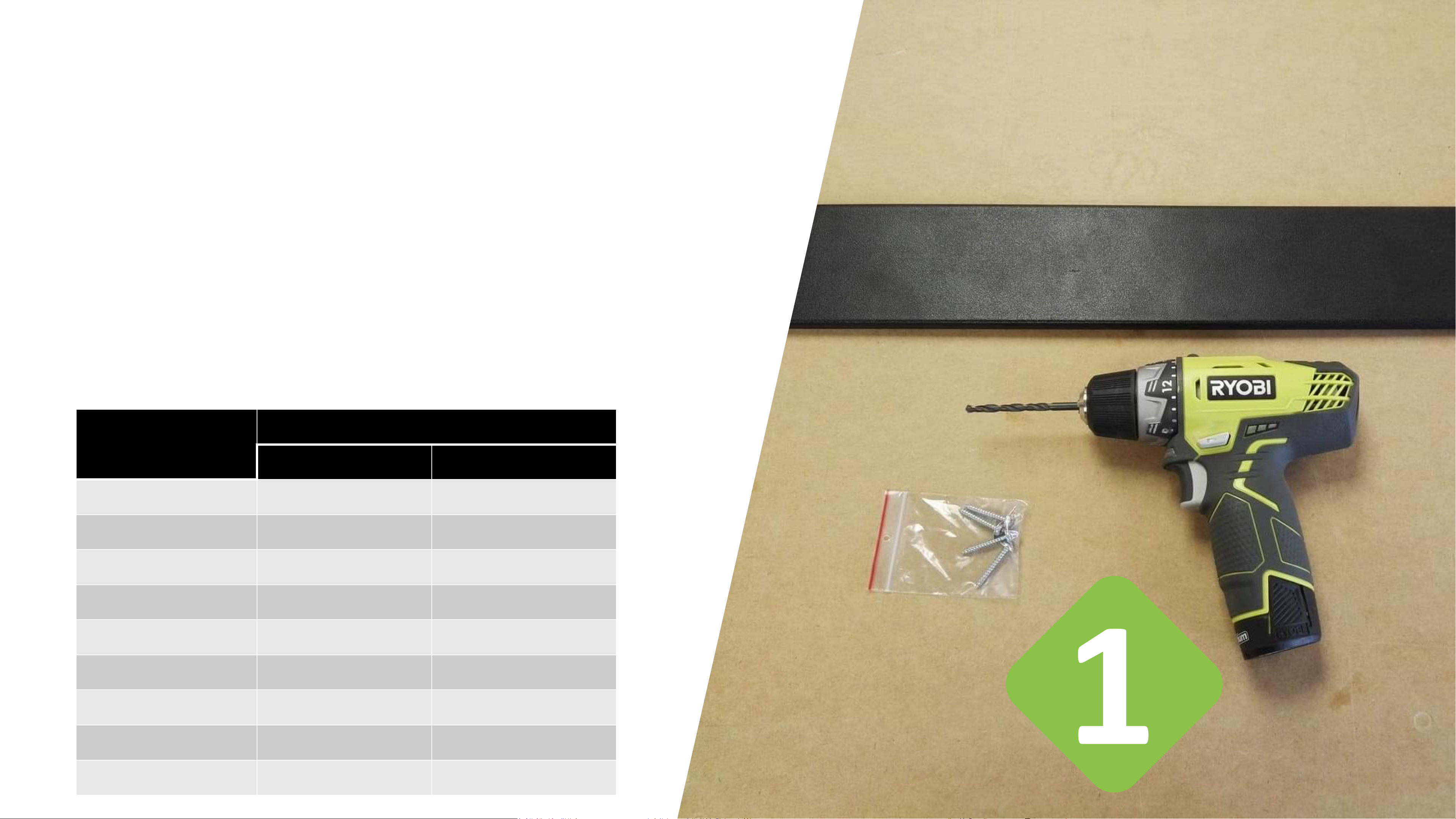
Required Tools
1 x Antenna model with flat or formed radome
1 x Electric drill
1 x Drill bit suitable for antenna specific max. THRU hole size
1 x Driver bit
4 x Screws
THRU hole size per antenna model:
Antenna name Max. THRU hole size
Flush Mount
Bracket mount
B6031
5.5 mm
4.5 mm
A7030C
6 mm
4.5 mm
A1030
4 mm
4.5 mm
A5060
4 mm
4.5 mm
A8060
6 mm
NA
A8065
6 mm
NA
A1115
4.5 mm
4.5 mm
A1130
4.5 mm
4.5 mm
A1163
4.5 mm
4.5 mm
5
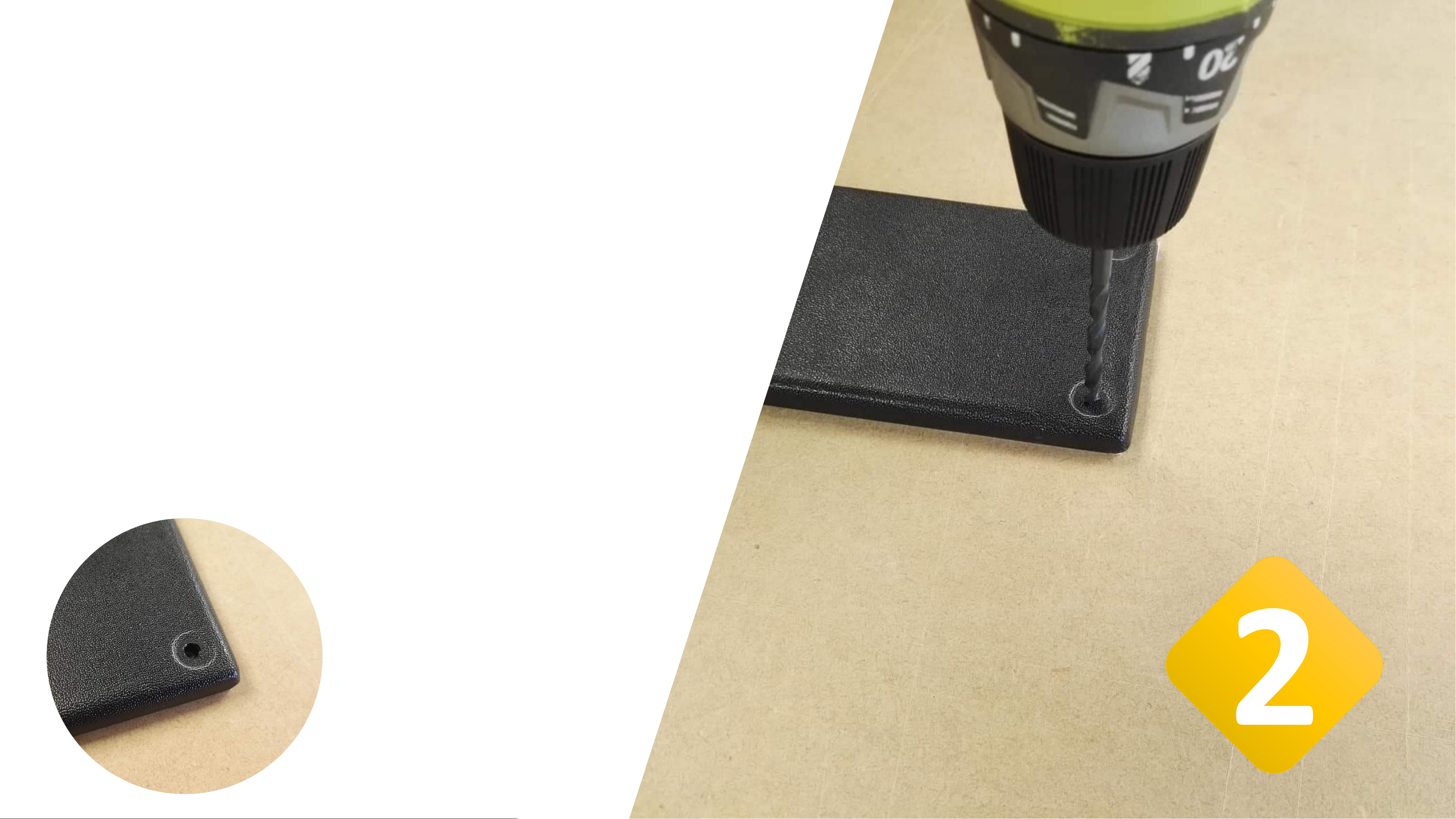
Drill a Pilot hole –
Formed Radome
Place the antenna on a flat surface to prevent the antenna
from bending in the process. We recommend using a
sacrificial piece of wood to protect the surface from being
damaged by the drill bit.
Position the drill bit on the dimple in the corner of the
antenna. Refer to the table on page 3 for antenna specific
max. THRU hole size.
Drill through carefully.
Drilled
through
pilot hole
6
 Loading...