


MOUNTING INSTRUCTIONS GUIDE
Using Integrated Mounting Guides, Pre-drilled Holes or Attach Brackets
For Picture Frame and Flat Radome Antennas
1

CONTENT
How to Use Integrated Mounting Guides and Pre
-drilled Holes
Page 03
How to Attach Brackets to Picture Frame and Flat
Radome Antennas
Page 09
How to Attach the Adhesive VESA Backplate for
Small Antennas
Page 13
2
2
2

How to Use Integrated Mounting Guides
and Pre-drilled Holes
3

Mounting Instructions
This document demonstrates step-by-step
how to flush mount the antenna models with
both a formed and flat radome using screws.
Some models with formed radomes include
drill guides shown in [Fig. 1], which can be
drilled through without damaging the
antenna. Models without drill guides on the
radome have pre-drilled holes on the rear of
the antenna to be used as guides [Fig. 2].
4
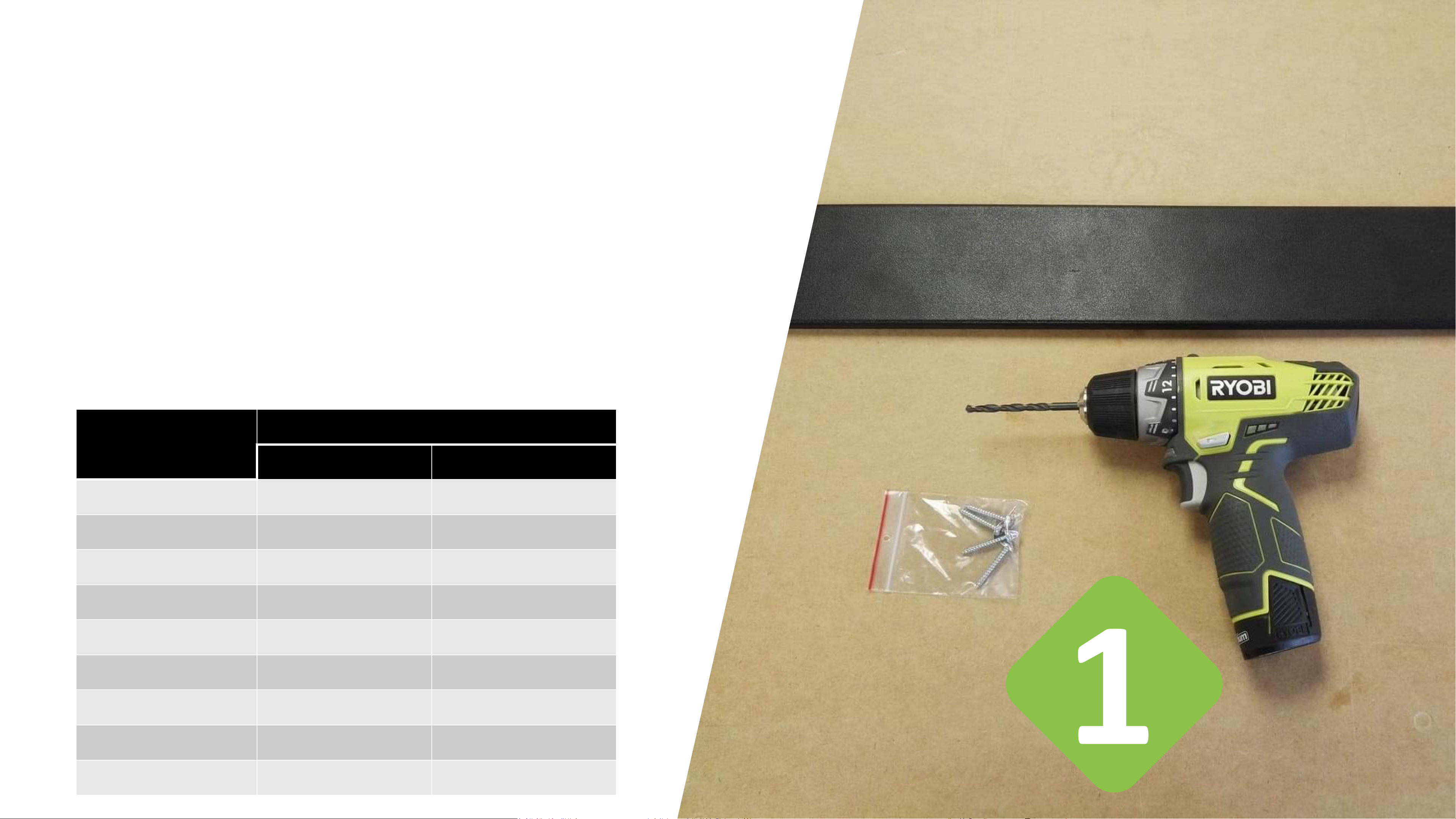
Required Tools
1 x Antenna model with flat or formed radome
1 x Electric drill
1 x Drill bit suitable for antenna specific max. THRU hole size
1 x Driver bit
4 x Screws
THRU hole size per antenna model:
Antenna name Max. THRU hole size
Flush Mount
Bracket mount
B6031
5.5 mm
4.5 mm
A7030C
6 mm
4.5 mm
A1030
4 mm
4.5 mm
A5060
4 mm
4.5 mm
A8060
6 mm
NA
A8065
6 mm
NA
A1115
4.5 mm
4.5 mm
A1130
4.5 mm
4.5 mm
A1163
4.5 mm
4.5 mm
5
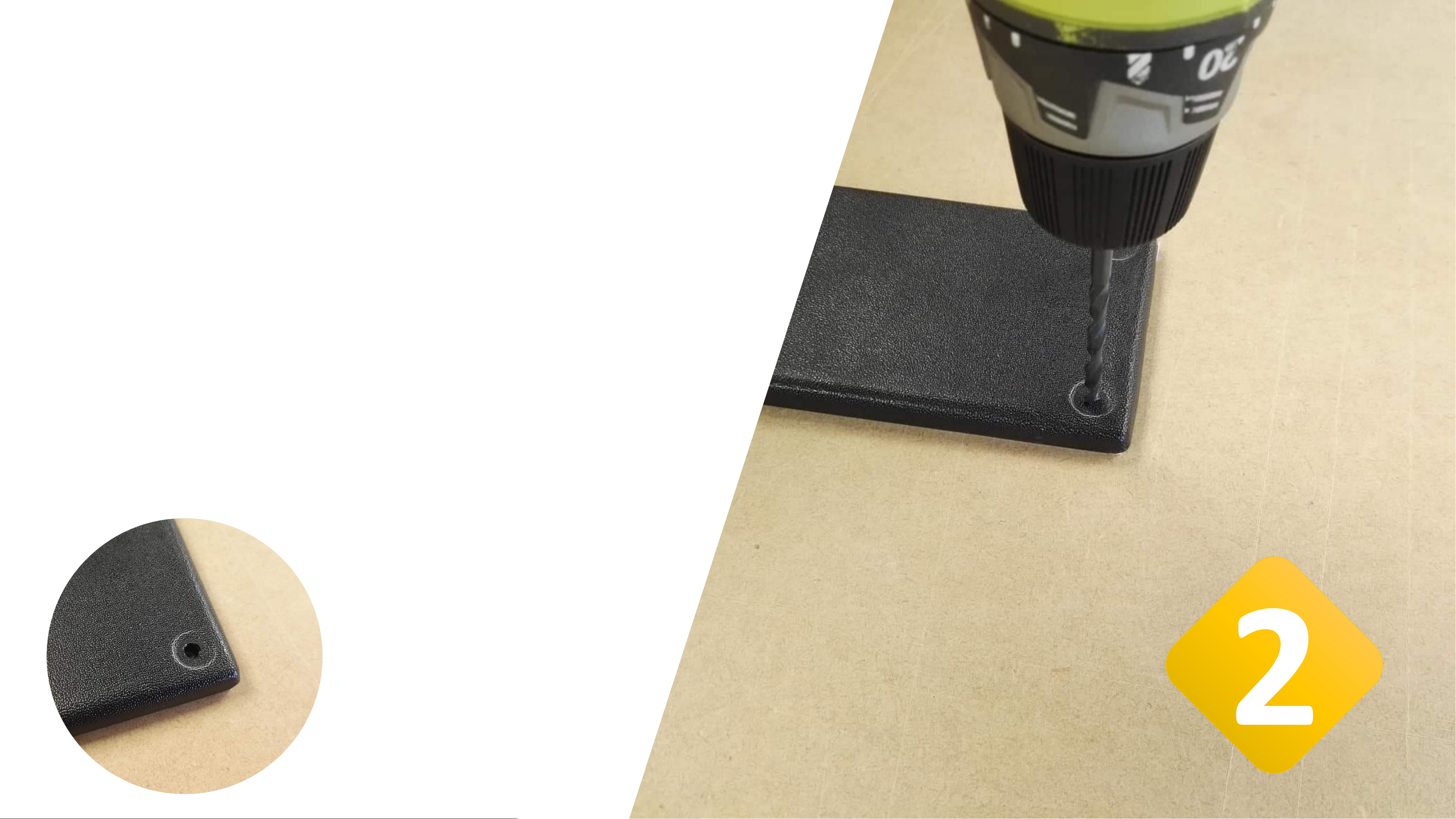
Drill a Pilot hole –
Formed Radome
Place the antenna on a flat surface to prevent the antenna
from bending in the process. We recommend using a
sacrificial piece of wood to protect the surface from being
damaged by the drill bit.
Position the drill bit on the dimple in the corner of the
antenna. Refer to the table on page 3 for antenna specific
max. THRU hole size.
Drill through carefully.
Drilled
through
pilot hole
6

Drill a Pilot hole –
Flat Radome
Place the antenna on a flat surface to prevent the
antenna from bending in the process. We recommend
using a sacrificial piece of wood to protect the surface
from being damaged by the drill bit.
Position the drill bit inside the hole that is pre-drilled
on the rear of the antenna. Refer to the table on page 3
for antenna specific max. THRU hole size.
Drill through carefully.
Drilled
through
pilot hole
7

Flush Mount the Antenna
Exchange the drill bit with the driver bit.
Hold the white ACM-side of the antenna
against the surface, where it is intended to be
mounted.
Place the screw in the pilot hole and screw it
in as required.
8

9
How to Attach Brackets to Picture Frame
and Flat Radome Antennas

Mounting Instructions
This document demonstrates step-by-step
how to attach a bracket to antenna models
with both a Picture Frame and flat radome
using screws.
Some models with flat radomes include drill
guides on the rear of the antenna which can
be drilled through without damaging the
antenna. For instructions please refer to page
3 of this document.
10

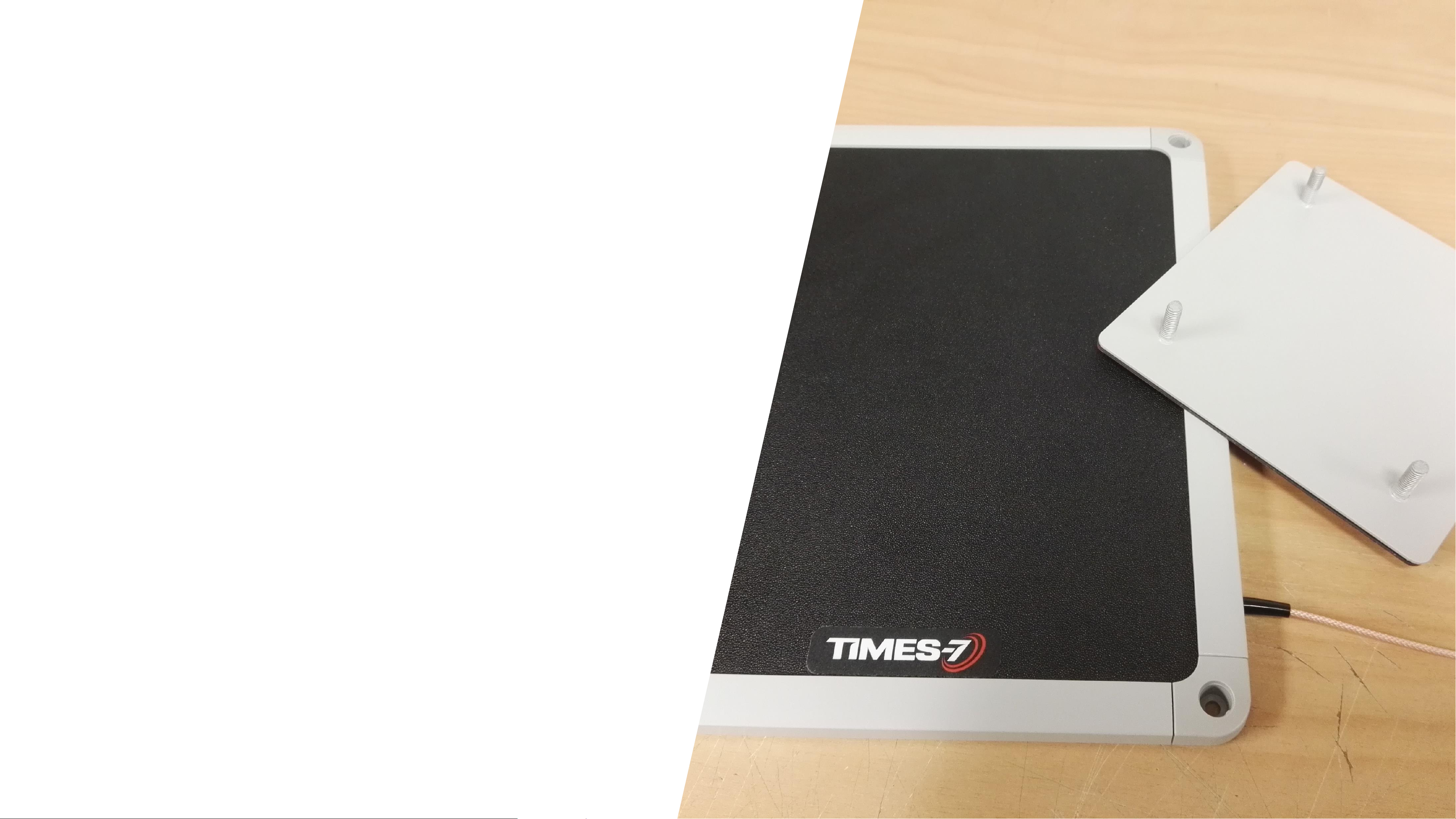
Attach Bracket – Picture Frame Antenna
(A4030C/L, A6031, A6032, A6034, A6034S)
• Using the supplied M4 mounting screws, secure the
bracket to the antenna using a nut and spring washer as
shown in Fig. 1-3.
• Tighten screws until the spring washers are flat, but
take care not to over tighten
• Plastic caps can then be used to cover the tops of the
screws as shown in Fig. 4.
Fig. 3Fig. 2Fig. 1 Fig. 4
11

Attach Bracket
– Flat Radome
• Antennas with a flat
radome must be pre-drilled
first using a 4mm drill bit.
• Use the pre-drilled holes
on the back of the antenna
as a guide to drill through
the radome.
• The bracket can then be
attached to the antenna in
the same way as the
picture frame antennas
(page 10), with care being
taken to not overtighten
the screws.
12

13
How to Attach the Adhesive VESA Backplate
for Small Antennas
Required Parts
• The antenna to be used
• An adhesive VESA mounting plate
• Isopropyl alcohol
• Cleaning cloth
• Scalpel
14

Clean surface with IPA
Using a clean cloth, use isopropyl alcohol
to briefly but thoroughly clean the
antenna surface that is to be adhered to.
Ensure all dust, debris and any grease or
oil marks are removed as these may
prevent the mounting plate from
adhering firmly.
15

Remove film and check
for bubbles
Carefully inspect the surface for any
bubbles that may have formed under the
surface of the adhesive as they may
prevent a strong bond.
Using the tip of a scalpel blade, pierce
any bubbles. This is best done when the
red film is still applied, so that the
pierced bubbles can be pushed out
without making contact with the
adhesive surface.
16

Attach the bracket to the
antenna
Remove the red protecting film. Using firm
and even pressure, apply the backplate to the
center of the antenna surface. Maintain firm
pressure for 30 seconds to ensure a strong
bond.
Allow the adhesive to settle for at least 10
minutes before being fitted to a bracket, in
order to give the adhesive time to form a
secure bond.
17

Contact our Customer Support
Feel free to contact us with any questions.
We are happy to help.
Call us +64 4 9746566
or write an Email to sales@times-7.com
© 2019 Times-7 Research Ltd. All rights reserved. Specifications are subject to change without
notice. Instruction Guide v2
18
 Loading...