

Page 1
MODEL 672
3.42"
2.88"
2.25"
1.75"
2.44”
TIME MARK is a division of
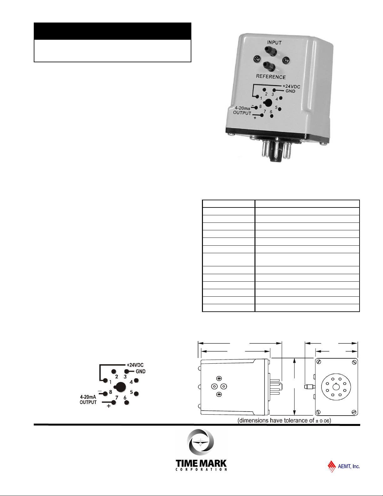
Pressure Transducer
0-15 psi Air Pressure Input
4-20 mA Output
5-Year Unconditional Warranty
DESCRIPTION
The Model 672 Pressure Transducer, part of the 600
series line of instrumentation controls, is a differential
pressure transducer. The 0-15 psi input allows the
Model 672 to output a proportional 4-20mA signal. It
can be DIN rail-mounted or mounted in a standard 8-pin
socket.
The Model 672 may be used to provide the input signal
for other instrumentation controls, including the
following Time Mark controls in the 600 series
instrumentation line:
Model 660 Trip Control
Model 661 Alarm Control
Model 662 Pump Up Control
Model 663 Pump Down Control
Model 670 Buffer/Scalar
Model 681 Digital Meter
PIN DIAGRAM
SPECIFICATIONS
Model 672
Input Voltage 24VDC ± 5%
Power Consumption 1W maximum
Air Pressure Input 0 to 15 psi
Max. Air Pressure 30 psi
Input Air Supply Fitting 3/16” I.D. tubing
Repeat Accuracy ± 1%
Signal Output 4-20mA proportional to 0-15 psi
(in water: 0-15 psi = 0 to 34.6 feet at 77º F)
Max. Load Resistance 500 ohms
Compensated Temp +32º to +158º F
Operating Temp -13º to +185º F
Enclosure Material ABS plastic
Mounting 8-pin socket (*order separately)
Weight 3 oz.
* Order 8-pin socket number 51X120
DIMENSIONS
01/2012
© 2012 TIME MARK CORPORATION
Page 2
MODEL 672
TIME MARK is a division of
Pressure Transducer
READ ALL INSTRUCTIONS BEFORE INSTALLING, OPERATING OR SERVICING THIS DEVICE.
KEEP THIS DATA SHEET FOR FUTURE REFERENCE.
GENERAL SAFETY
THE MODEL 672 PRESSURE TRANSDUCER IS NOT TO BE USED WITH INPUT VOLTAGES OTHER THAN
24VDC. ALL ELECTRICAL POWER SHOULD BE REMOVED WHEN CONNECTING OR DISCONNECTING
WIRING. THIS DEVICE AND WIRING SHOULD BE INSTALLED AND SERVICED BY QUALIFIED PERSONNEL.
Installation Instructions
INSTALLATION
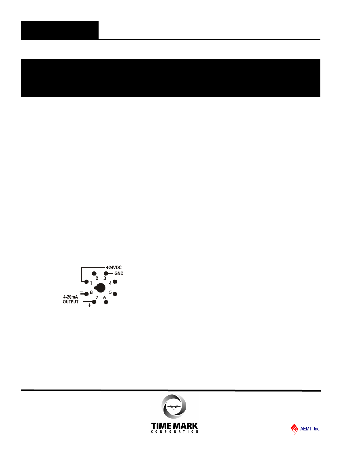
Observing the pin diagram shown below and on the
unit, connect the Model 650 Power Supply, or other
regulated 24 VDC power source to pins 1 and 3 on the
8-pin socket.
Connect the output leads for the 4-20mA current loop to
pins 7 and 8. Pay careful attention to polarity.
NOTE: When installing the Model 672 Transducer in areas
of high humidity or contamination, it is recommended that the
base area and all exposed metal parts of the socket be coated
liberally with a good quality silicone grease, such as Dow
Corning DC-4 or DC-4X. Insert the unit into the socket and
wipe off excess grease around the base. This will prevent the
entrance of moisture and other contaminates into the base
and socket areas.
PIN DIAGRAM
Connect a 3/16” I.D. air hose to the Model 672 INPUT
hose connection. Connect the other end of the input
hose to the measurement device air pressure output.
Connect a 3/16” I.D. air hose to the Model 672
REFERENCE hose connection. Connect the other end
of the input hose to the reference pressure source. If
the reference source is atmospheric pressure, do
not connect a hose to the REFERENCE hose
connector.
TROUBLESHOOTING
Should the Model 672 Pressure Transducer fail to
operate, check the power supply connections, making
sure that the polarity and voltage levels are correct.
Verify that all electrical connections are firmly attached
to the terminals.
Check the full length of the air hose and hose
connections, to insure there are no pressure leaks.
Connect a known pressure source to the INPUT
connection, while measuring the output current from
pins 7 and 8.
The output current must have a complete circuit,
through the controller, returning to the pressure
transducer. Should problems persist, contact the
factory for assistance.
WARRANTY
This product is warranted to be free from defects in
materials and workmanship, and is covered by our exclusive 5-year Unconditional Warranty. Should this
device fail to operate for any reason, we will repair it for
five years from the date of manufacture. For complete
warranty details, see the Terms and Conditions of
Sales page in the front section of the Time Mark catalog or contact Time Mark at 1-800-862-2875.
01/2012
© 2012 TIME MARK CORPORATION
 Loading...