

Page 1
60 Hz
COMMON
GROUND
COMMON
GROUND
32 VDC
24 VDC
AC 1
AC 2
AC
GROUND
1 8
7
6
5
4
3
2
MODEL 650
TIME MARK is a division of
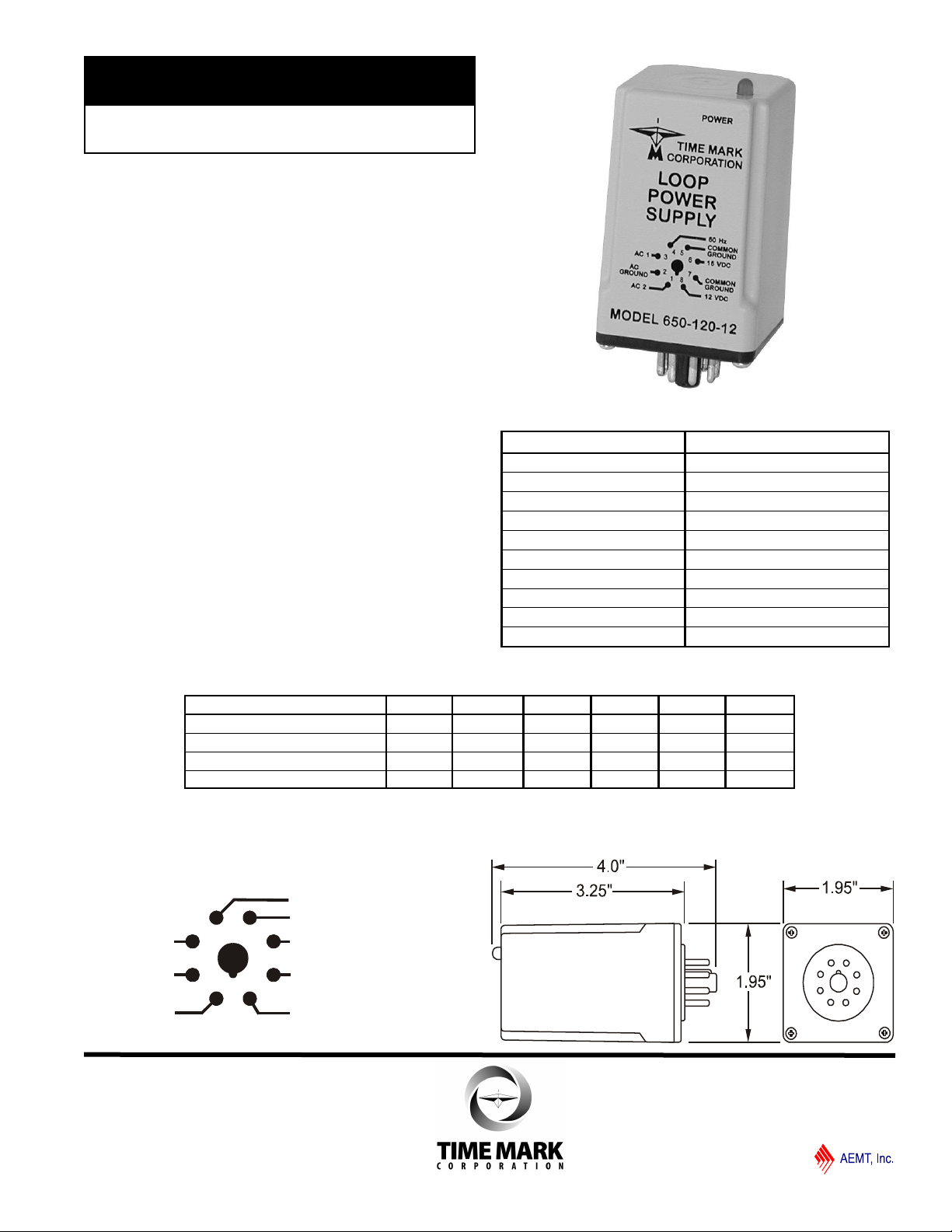
Loop Power Supply
Dual DC Voltage Outputs
60 Hz Pulse Output
5 Year Unconditional Warranty
DESCRIPTION
The Model 650 Loop Power Supply provides DC
power for instrumentation control modules.
Each option provides three output selections as shown
in the table below. For example the Model 650-240-24
has output options of 24VDC regulated, 32VDC
unregulated, and 60Hz pulse at 46 peak volts.
All outputs for the Model 650 are floating, electrically
isolated from ground. A power status indicator (LED)
is located on the top of the unit. The POWER LED
comes ON when power is applied.
Applications for this device include two-wire loop transducers (pressure, voltage, or current), alarm indicators,
meters and timers.
Model No. - Input Voltage - Output Regulated Example: 650-240-12
Option Number -120-5 -120-12 -120-24 -240-5 -240-12 -240-24
Input VAC 120 120 120 240 240 240
Output VDC Regulated 5 12 24 5 12 24
Output VDC Unregulated (Loaded) 16 16 32 16 16 32
60Hz pulse (peak voltage) 23 23 46 23 23 46
MODEL 650 ORDERING OPTIONS
SPECIFICATIONS
Model 650
Supply voltage See table below
Operating frequency 60Hz
Power consumption 6 watts maximum
Outputs See table below
Maximum combined current 150mA
Operating temperature -20° to +50º C
Humidity tolerance 0-97% w/o condensation
Enclosure material ABS plastic
Weight 9.5 ounces
Mounting 8-pin socket (*order separately)
* Order 8-pin socket number 51X120
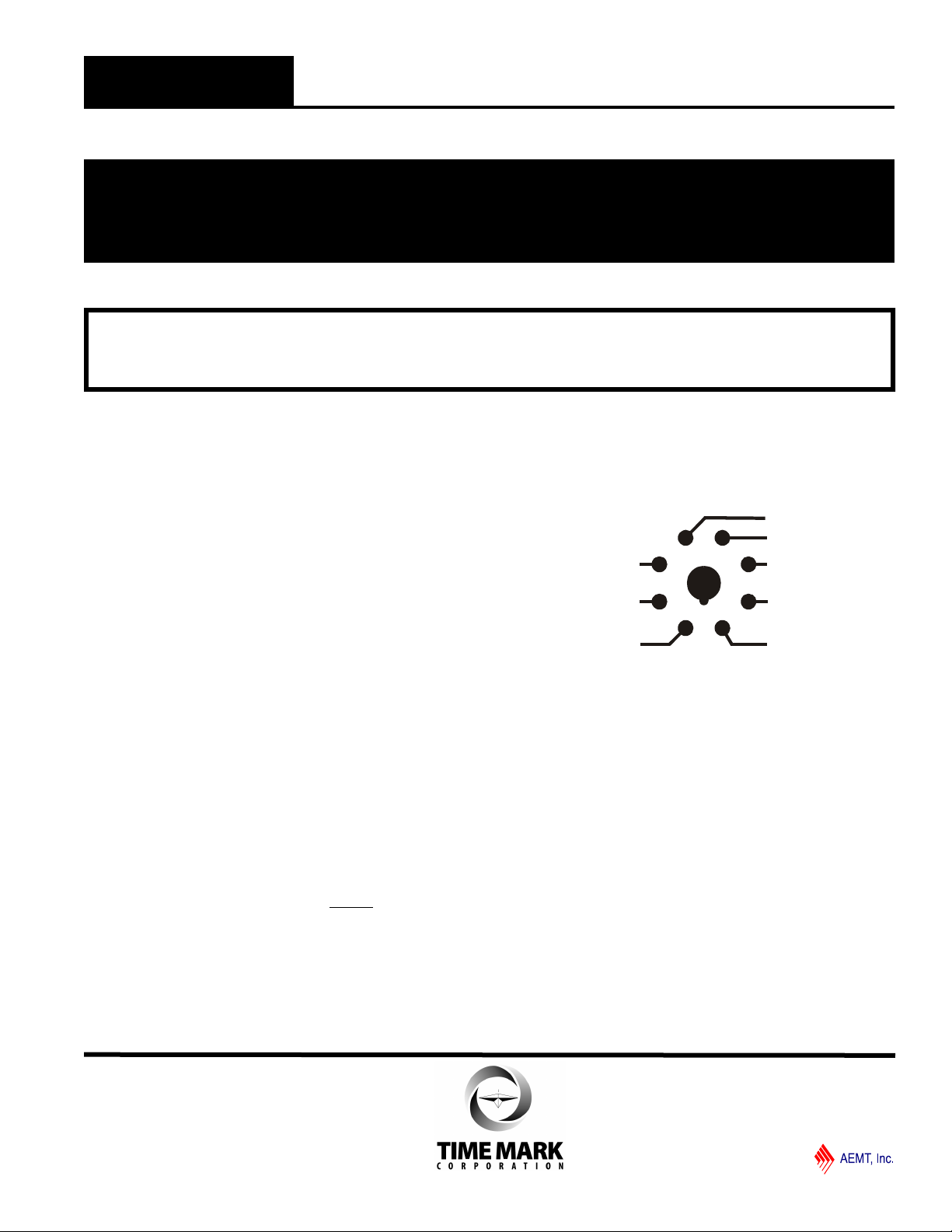
PIN DRAWING (Bottom view of unit)
DIMENSIONS
12/2012
© 2012 TIME MARK CORPORATION
Page 2
60 Hz
COMMON
GROUND
COMMON
GROUND
32 VDC
24 VDC
AC 1
AC 2
AC
GROUND
1 8
7
6
5
4
3
2
TIME MARK is a division of
MODEL 650
Loop Power Supply
READ ALL INSTRUCTIONS BEFORE INSTALLING, OPERATING OR SERVICING THIS DEVICE.
KEEP THIS DATA SHEET FOR FUTURE REFERENCE.
GENERAL SAFETY
POTENTIALLY HAZARDOUS VOLTAGES ARE PRESENT AT THE TERMINALS OF THE MODEL 650.
ALL ELECTRICAL POWER SHOULD BE REMOVED WHEN CONNECTING OR DISCONNECTING WIRING.
THIS DEVICE SHOULD BE INSTALLED AND SERVICED BY QUALIFIED PERSONNEL.
Installation Instructions
The Model 650 Loop Power Supply is not to be used with input voltages other than those for which the unit
was designed; 120VAC for the three “120” option units, or 240VAC for the three different “240” option units.
INSTALLATION
Connect the 60Hz input power to pins 1, 2 and 3 on the
8-pin socket, following the Model 650 base diagram
pictured on the unit (and on this data sheet).
Depending on the desired DC voltage output, connect
the DC load device to the appropriate socket output
pins.
NOTE: When installing the Model 650 Power Supply
in areas of high humidity or contamination, it is
recommended that the base area and all exposed
metal parts of the socket be coated liberally with a
good quality silicone grease, such as Dow Corning DC-
4 or DC-4X. Insert the unit into the socket and wipe off
excess grease around the base. This will pre-vent the
entrance of moisture and other contaminates into the
base and socket areas.
TROUBLESHOOTING
Should the Model 650 Loop Power Supply fail to
operate, check all connections. Verify that the proper
input source voltage is present, and check all fuses.
After you have verified the input voltage, note the
following: The power status indicator (LED), located on
top of the unit will be OFF if the output is shorted or
overloaded. Should problems persist, disconnect the
output lines, and measure the output voltages.
WARNING
NOTE: This pin drawing represents the bottom view of
the Model 650 Loop Power Supply module.
WARRANTY
This product is warranted to be free from defects in
materials and workmanship, and is covered by our
exclusive 5-year Unconditional Warranty. Should this
device fail to operate for any reason, we will repair it for
five years from the date of manufacture. For complete
warranty details, see the Terms and Conditions of Sales
page in the front section of the Time Mark catalog or
contact Time Mark at 1-800-862-2875.
12/2012
© 2012 TIME MARK CORPORATION
 Loading...