

Page 1
C
L
3.88"
3.0"
0.44"
3.03"
Holes are symetrical
about center line.
0.203" 4 PL.
5.5"
6.06"
0.55"
2.63"
0.28"
MOTOR
4-20mA
OUTPUT
REVERSE WIRES TO CT
IF MOTOR FAILS TO RUN
FOR MORE THAN THE INITIAL
2 SECOND PERIOD.
MODEL 276A-xx
L1
L2
MANUAL
RESTART
120VAC
COIL
TIME MARK is a division of
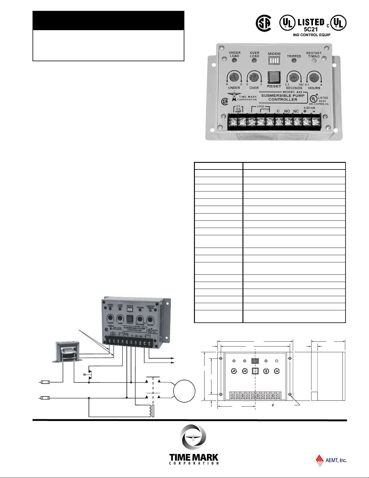
MODEL 422
Submersible
Pump Controller
Monitors True Motor Power
(volts x current x power factor)
Detects Motor Overload or Underload
Operates on 120 or 240VAC,
Single-phase or 3-phase
Built-in Trip and Restart Delay Options
SPECIFICATIONS
DESCRIPTION
The Model 422 Submersible Pump Controller detects
an overload or underload condition on all types of
running pump motors: suction pumps, submersible
pumps, etc.
This Monitor detects the actual power used (voltage x
current x power factor) and is more sensitive than
simple current monitors. The 422 can be used with
single phase pumps or, using the Model 276C current
transducer, with 3-phase pumps. Matching CT’s allow
the Model 422 to be used with most pump motor sizes.
Optional trip and restart delays are provided.
TYPICAL APPLICATION -single-phase monitoring
Model 422
Input Voltage Range 100-130VAC or 200-250VAC
Frequency 50/60Hz
Power Consumption
Nominal Current
Minimum Current
Current Adjustment 0 - 5 amps x PF
Current Output 4-20mA for chart recorders
Repeat Accuracy 1% (fixed conditions)
Output SPDT 10A at 240VAC resistive
Expected Relay Life Mech: 10 million operations
Trip Delay
Restart Delay
Indicators Red LED: Overload or Underload; tripped
Transient Protection 2500V for 10ms
Operating Temp - 20º to 131º F
Humidity Tolerance 97% w/o condensation
Enclosure Material ABS plastic
Weight 1 lb.
Agency Approvals UL Listed to US and Canadian safety
0.5 VA max.
2.5 amps
0.25 amps
Elec: 100,000 operations at rated load
OFF or 0.3 to 180 seconds
OFF or 0.1 to 4 hours
Yellow LED: Restart timing
standards CSA Certified
DIMENSIONS
Page 1 of 8 11/2011
© 2011 TIME MARK CORPORATION
Page 2
TIME MARK is a division of
MODEL 422
READ ALL INSTRUCTIONS BEFORE INSTALLING, OPERATING OR SERVICING THIS DEVICE.
Submersible Pump Controller
KEEP THIS DATA SHEET FOR FUTURE REFERENCE.
APPLICATION GUIDE
GENERAL
This application guide is written for equipment designers,
maintenance personnel, electrical contractors, etc.
It is intended to aid in the installation of the Model 422
Submersible Pump Controller into pump protection systems.
The notes and diagrams deal with methods of protecting motors in
the event of an underload condition or an overload condition.
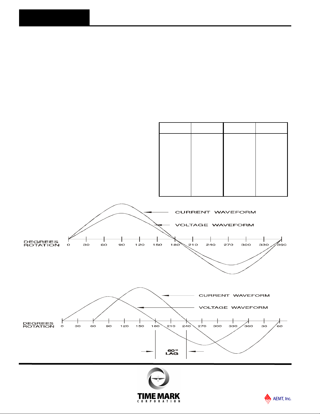
THEORY
The need for a system to detect an underload condition other than
by the simple monitoring of current becomes clear when
examining the following waveforms.
In a purely resistive circuit, as in Figure 1, the current (amps) is
directly proportional to the power (watts) being consumed. To find
the power, multiply the voltage across the load times the current
through the load. The result is in watts (V x A = W).
In Figure 2, When the load is not resistive, but inductive as it is
with a motor, the formula is no longer correct. The inaccuracy
occurs because the current and the voltage waveforms are not in
phase.
The current waveform lags the voltage waveform by as much as
90 degrees in a completely unloaded condition, or as little as 5 or
10 degrees in a fully loaded condition.
The current, as measured with an ammeter, may only vary a slight
amount as the motor changes from a fully loaded condition to a
completely unloaded condition. This makes it difficult to detect an
unloaded condition by simply monitoring current alone.
To obtain an accurate picture of real power consumption of any
inductive device, such as a motor, the formula V x A x Cosø = W
is used.
The Cosø is a multiplication factor derived from the number of
degrees of lag between the current and voltage waveforms.
This is called the “power factor” (or “PF”). The power factor is the
natural cosine of the degrees of lag:
Degrees
of lag
0 1.000 50 0.643
5 0.996 55 0.574
10 0.985 60 0.500
15 0.966 65 0.423
20 0.940 70 0.342
25 0.906 75 0.259
30 0.866 80 0.174
35 0.819 85 0.087
40 0.766 90 0.000
45 0.707
Power
Factor
Degrees
of lag
Power
Factor
Figure 1. RESISTIVE
LOAD
With a purely resistive load, the current and voltage
waveforms are occurring simultaneously.
Figure 2. INDUCTIVE
LOAD
With an inload, the current waveform lags
the voltage waveform by 60°.
Page 2 of 8 11/2011
© 2011 TIME MARK CORPORATION
Page 3

TIME MARK is a division of
2.38"
1.95"
1.63"
Secondary
Space for Primary turn:
0.25" 0.38"x
1.25"
0.43"
.187" dia.
Secondary terminals
(0 - 5 amps)
Loop one leg of AC
line thru transformer
as shown
MODEL 422
Submersible Pump Controller
APPLICATION GUIDE
Example: TRUE POWER CONSUMED BY AN AC
MOTOR
For this example we will use a 3-horsepower, 230 volt,
single phase motor.
Condition 1 represents the motor being used at near full
load, while Condition 2 represents a drop in motor load.
Comparing the results of this example, the motor
current decreased only 10% with a drop of 61% in the
motor load (input power). A drop in pump motor power
cannot be accurately measured by only monitoring the
current and voltage.
By monitoring the phase relationship and applying the
resultant power factor an accurate and selective
method of sensing changes in true power consumption
can be obtained.
The Model 422 Controller is based on the above
principal of detecting the actual power used, and is
more sensitive than simple current monitors.
ADDITIONAL FEATURES
As described previously, the Model 422 would fulfill the
basic requirements in most pump motor protection
control systems. However, there are situations which
would require the pump to restart automatically after a
preset time.
The Model 422 has an adjustable restart timer for
such applications. This timer has a range of 0.1 to 4
hours. If the restart timer is not needed, turn it off with
DIP switch 2.
If restart timing is needed for an underload condition
only, the overload restart can be turned off with DIP
switch 1.
Resetting the Model 422 is accomplished by cycling the
power off and back on, pressing the RESET button, or
by using the restart timer (DIP switch 2).
Some applications require a trip delay period before
shutting down the pump. The Model 422 has a built-in
trip delay timer. The timing range is from 0.3 to 180
seconds. The trip delay timer can be turned off with
DIP switch 4.
Example: (V x A x Cosø = Watts)
Condition 1
230 volts x 10 amps x 0.985 PF = 2265.5 watts
Condition 2
230 volts x 9 amps x 0.423 PF = 875.6 watts
Refer to the chart under INSTALLATION (pg 4) for all
DIP switch settings.
A 4-20mA output is provided for monitoring power
consumption. A 4mA output is equal to 0 watts and a
20mA output is equal to 600 watts at 120 V or 1200
watts at 240 V.
This signal can be sent to a strip chart recorder, a
process controller, computer, etc.
INPUT CURRENT REQUIREMENTS
The CT input of the Model 422 is the isolated winding of
a small current transformer within the unit. Ideally, the
current range needed should be between 2 and 3.5
amps for a fully loaded motor.
Polarity of the wires connected to the CT terminals is
critical to achieve the correct phase relationship
between the current and voltage waveforms as
described earlier.
This is simple to determine after the installation is
complete (refer to the ADJUSTMENT PROCEDURE, pg
5).
If the full load motor current is 3.5 amps or less, and the
pump motor is a single-phase type, connect one leg of
the motor current directly into the Model 422.
Figure 3 shows the Model 276A and Figure 4 shows
the Model 276B Current Transformers; available from
Time Mark.
Figure 3. MODEL 276A CURRENT TRANSFORMER
Page 3 of 8 11/2011
© 2011 TIME MARK CORPORATION
Page 4

2.6"
3.6"
.187" dia. typical
4.0"
2.3"
4.6"
TIME MARK is a division of
3.90"
2.00"
0.44"
1.25"
4.50"
3.88"
(2) 0.27" x 0.44" slots
B
C
MODEL 422
APPLICATION GUIDE INSTALLATION INSTUCTIONS
Figure 4. MODEL 276B CURRENT TRANSFORMER
Use the chart below to cross reference your motor horsepower
to a Time Mark single-phase or 3-phase current transformer.
Figure 5. CURRENT TRANSFORMER CHART
Motor
1 1/2 276A-30 276A-15 276A-10 *
7 1/2 276B-150 276B-60 276A-35 276A-20
100 276B-400 276B-200
125 276B-250
150 276B-300
200 276B-400
250 276B-500
300 276B-600
350 276B-700
400 276B-750
500 276B-1000
Submersible Pump Controller
276B Series
50 - 500 600 - 1200
B = 0.87”
C = 1.56” C = 2.06”
Time Mark Model Number
Single-Phase 3-Phase
HP
1/4 276A-10
1/3 276A-15
1/2 276A-15 276A-10
3/4 276A-20 276A-10 * *
1 276A-25 276A-15 276A-10
2 276A-35 276A-20 276A-10 *
3 276B-50 276A-25 276A-15 276A-10
5 276B-80 276A-40 276A-25 276A-15
10 276B-150 276B-75 276A-40 276A-20
15 276B-60 276A-30
20 276B-80 276A-40
25 276B-100 276B-50
30 276B-150 276B-60
40 276B-150 276B-75
50 276B-200 276B-100
60 276B-250 276B-150
75 276B-300 276B-150
120VAC 240VAC 240VAC 480VAC
* *
* *
* Direct connection to Model 276C (see page 8)
* * Direct connection to Model 422
B = 0.87”
*
*
*
3-PHASE INSTALLATION
The basic Model 422 Controller is designed for use with
single-phase pump motors. However, it can easily be
used in 3-phase applications by installing the current
cancelling transformer, Model 276C. The Model 276C
(figure 6) monitors two of the three phases, and cancels
the effect of the current signal in the third phase, which
would otherwise cause a phase shift error in the Model
422.
Figure 6. MODEL 276C
IMPORTANT NOTE:
In 3-phase applications, the current inputs must
come from the same phases providing the voltage
input. The applications schematics shown on the
last page describe the interconnections.
INSTALLATION
Mount the Model 422 in the control panel or in a suitable
enclosure. Connect the voltage and current inputs to
the appropriate terminals on the Model 422 Monitor.
If the 4-20mA output is used, connect it across a 300
resistive load. Set the four MODE switches on the
Model 422 according to the chart below. During the
initial setup you may wish to disable all time delays.
DIP SW MODE ON OFF
After the system is completely installed, a simple test and
adjustment will insure that the polarity and threshold are
correct.
1
2
3
4
Overload Restart Disabled Enabled
Restart Delay Enabled Disabled
Reset Button Enabled Disabled
Trip Delay Enabled Disabled
Page 4 of 8 11/2011
© 2011 TIME MARK CORPORATION
Page 5

TIME MARK is a division of
MODEL 422
Submersible Pump Controller
READ ALL INSTRUCTIONS BEFORE INSTALLING, OPERATING OR SERVICING THIS DEVICE.
KEEP THIS DATA SHEET FOR FUTURE REFERENCE.
GENERAL SAFETY
POTENTIALLY HAZARDOUS VOLTAGES ARE PRESENT AT THE TERMINALS OF THE MODEL 422.
ALL ELECTRICAL POWER SHOULD BE REMOVED WHEN CONNECTING OR DISCONNECTING WIRING.
THIS DEVICE SHOULD BE INSTALLED AND SERVICED BY QUALIFIED PERSONNEL.
INSTALLATION INSTRUCTIONS
ADJUSTMENT
Connect a temporary jumper across the NO contacts on
the Model 422 (this keeps the motor running as the
Model 422 trips off and resets).
With the correct voltage applied to the system, the
motor should start and run continuously. Make sure the
motor is running under its normally loaded condition.
With a clamp-type ammeter, measure the current in one
of the wires connected to the CT terminals on the Model
422. A reading between 2 and 3.5 amps should be
measured for best results. This current level can be
changed by exchanging the CT with a different ratio.
Turn the UNDER adjustment through its entire range
and find the spot where the UNDERLOAD LED just
illuminates.
Turn the UNDER adjustment until the LED just goes
out. If the UNDERLOAD LED is lit all the time, reverse
the two wires connected to the CT terminals and readjust.
Repeat this procedure for the OVER adjustment. If the
OVERLOAD indicator LED stays on all the time, the
current input may be incorrect. Check the CTs for
proper sizing.
Set the SECONDS adjustment for the appropriate TRIP
delay, and HOURS adjustment for the appropriate
RESTART delay, as required for the application.
Remove the jumper from the NO contacts; the motor
should continue to run. The adjustment is now
complete.
TROUBLESHOOTING
Should the Model 422 Submersible Pump Controller fail
to operate, check all connections to the device and its
control circuits. Insure that the proper voltage and
currents have been applied.
Check all fuses. Should the Model 422 operate
improperly, check that the CT is properly sized. Check
all DIP switch settings. If problems persist, contact the
factory for technical assistance.
OPERATION
When AC voltage is first applied, the output transfers
for approximately two seconds, completing the motor
control circuit and allowing the motor to come up to
speed.
If the power being used is within acceptable limits the
contacts remain energized and the motor continues to
run. If the power drops or rises outside the limits, the
contacts will open.
WARRANTY
This product is warranted to be free from defects in
materials and workmanship for one year. Should this
device fail to operate, we will repair it for one year from
the date of manufacture. For complete warranty
details, see the Terms and Conditions of Sales page in
the front section of the Time Mark catalog or contact
Time Mark at 1-800-862-2875.
Page 5 of 8 11/2011
© 2011 TIME MARK CORPORATION
Page 6

MOTOR
4-20mA
OUTPUT
REVERSE WIRES TO CT
IF MOTOR FAILS TO RUN
FOR MORE THAN THE INITIAL
2 SECOND PERIOD.
MODEL 276A-xx
L1
L2
MANUAL
RESTART
120VAC
COIL
MOTOR
4-20mA OUTPUT
REVERSE WIRES TO CT
IF MOTOR FAILS TO RUN
FOR MORE THAN THE INITIAL
2 SECOND PERIOD.
MODEL 276B-xx
L1
L2
MANUAL
RESTART
240VAC
COIL
TIME MARK is a division of
MODEL 422
Submersible Pump Controller
TYPICAL APPLICATIONS
SINGLE-PHASE, 120V, <3 HP
SINGLE-PHASE, 240V, 7.5 HP
Shows No Power Applied
Shows No Power Applied
Page 6 of 8 11/2011
© 2011 TIME MARK CORPORATION
Page 7

4-20mA
OUTPUT
REVERSE WIRES
TO CT IF MOTOR
FAILS TO RUN
FOR MORE THAN
THE INITIAL
2 SECOND PERIOD.
M
O
D
E
L
2
7
6
C
L1
L2
MANUAL
RESTART
240VAC
COIL
OBSERVE POLARITY
AS SHOWN
USE MODEL 276A-xx
MOTOR
L3
TIME MARK is a division of
MOTOR
4-20mA OUTPUT
REVERSE WIRES TO CT
IF MOTOR FAILS TO RUN
FOR MORE THAN THE INITIAL
2 SECOND PERIOD.
L1
L2
MANUAL
RESTART
240VAC
COIL
MODEL 276A-xx
MODEL 422
Submersible Pump Controller
TYPICAL APPLICATIONS
SINGLE-PHASE, 240V, 1/2 TO 5 HP
3-PHASE, 240V, 1 TO 10 HP
Shows No Power Applied
Shows No Power Applied
Page 7 of 8 11/2011
© 2011 TIME MARK CORPORATION
Page 8

4-20mA
OUTPUT
REVERSE WIRES
TO CT IF MOTOR
FAILS TO RUN
FOR MORE THAN
THE INITIAL
2 SECOND PERIOD.
M
O
D
E
L
2
7
6
C
MANUAL
RESTART
120VAC
COIL
MOTOR
OBSERVE POLARITY
AS SHOWN
USE MODEL 276B-xx
120VAC
480VAC
T
I
M
E
M
A
R
K
3
-
P
H
A
S
E
M
O
N
I
T
O
R
L1
L3
L2
4-20mA
OUTPUT
REVERSE WIRES
TO CT IF MOTOR
FAILS TO RUN
FOR MORE THAN
THE INITIAL
2 SECOND PERIOD.
M
O
D
E
L
2
7
6
C
L1
L2
MANUAL
RESTART
240VAC
COIL
OBSERVE POLARITY
AS SHOWN
MOTOR
L3
TIME MARK is a division of
MODEL 422
Submersible Pump Controller
TYPICAL APPLICATIONS
Over/Under Load & Phase Loss Protection
3-PHASE, 240V, <1 HP
THE INFORMATION PRESENTED IN THIS GUIDE IS CORRECT TO THE BEST OF OUR KNOWLEDGE. HOWEVER, TIME MARK CORPORATION
DOES NOT WARRANT THE APPLICATIONS AS OUTLINED NOR MAKE ANY OFFERS THAT THE CIRCUITS ARE FREE FROM PATENT
INFRINGEMENT. TIME MARK CORPORATION RESERVES THE RIGHT TO CHANGE OR ALTER SPECIFICATIONS AT ANY TIME.
Shows No Power Applied
Shows No Power Applied
Page 8 of 8 11/2011
© 2011 TIME MARK CORPORATION
 Loading...