

Page 1

12.0"
11.5"
5.5"5.0"
.187" dia
4.62"
3.25"
TIME MAR K is a division of
MODEL 403
Liquid Level
Controller
Dual run-time meters
Selectable lead/lag or automatic
alternation
Four sensing levels
Alarm outputs
Hand-off-auto controls
DESCRIPTION
The Model 403 Liquid Level Controller provides central
control of duplex pumping systems. The Model 403
includes pump alternating, visual run-time meters, handoff-auto (HOA) controls and alarm outputs.
Four level-sense inputs interface with float switches,
pressure switches, or other level sensing devices which
can provide a contact closure.
A SPST, normally-closed internal power-fail contact opens
when AC power 120VAC is connected to the controller,
and closes if power is lost or removed. Connections for
external remote alarm contacts, which must remain closed
for normal operation (or jumpered if not required), are
supplied for each pump.
If either circuit opens, the corresponding pump will be
locked out until the problem is corrected and the ‘Alarm
reset’ switch is pressed.
SPECIFICATIONS
MODEL 403
Input voltage 105-130VAC
Input frequency 60Hz
Power consumption 10W max.
Contacts SPST relay
Contact rating 10A at 240VAC resistive
Float Switch Potential 12VDC at 1mA
Transient protection 2500 V for 10ms
Operating temperature - 20º to +140º F
Display
Humidity tolerance 0-97% without condensation
Expected relay life
Case material 20 gauge Steel
Termination Removable terminal strip
Weight
Mechanical: 10 million operations
Electrical: 100,000 operations at rated load
to 99,999.9 non-resettable
4.9 lbs
DIMENSIONS
Page 1 of 4 11/2011
© 2011 TIME MARK CORPORATION
Page 2
TIME MAR K is a division of
MODEL 403
Liquid Level Controller
READ ALL INSTRUCTIONS BEFORE INSTALLING, OPERATING OR SERVICING THIS DEVICE.
KEEP THIS DATA SHEET FOR FUTURE REFERENCE.
POTENTIALLY HAZARDOUS VOLTAGES ARE PRESENT AT THE TERMINALS OF THE MODEL 403.
ALL ELECTRICAL POWER SHOULD BE REMOVED WHEN CONNECTING OR DISCONNECTING WIRING.
DO NOT EXCEED THE OUTPUT OR INPUT RATINGS, AS STATED IN THE SPECIFICATIONS.
PROTECT THE UNIT WITH PROPERLY RATED FUSES.
DO NOT INSTALL IN DAMP OR MOIST AREAS.
THIS DEVICE SHOULD BE INSTALLED AND SERVICED BY QUALIFIED PERSONNEL.
GENERAL SAFETY
Installation Instructions
INSTALLATION
Mount the controller in a suitable enclosure. Unplug the
terminal connectors from the controller.
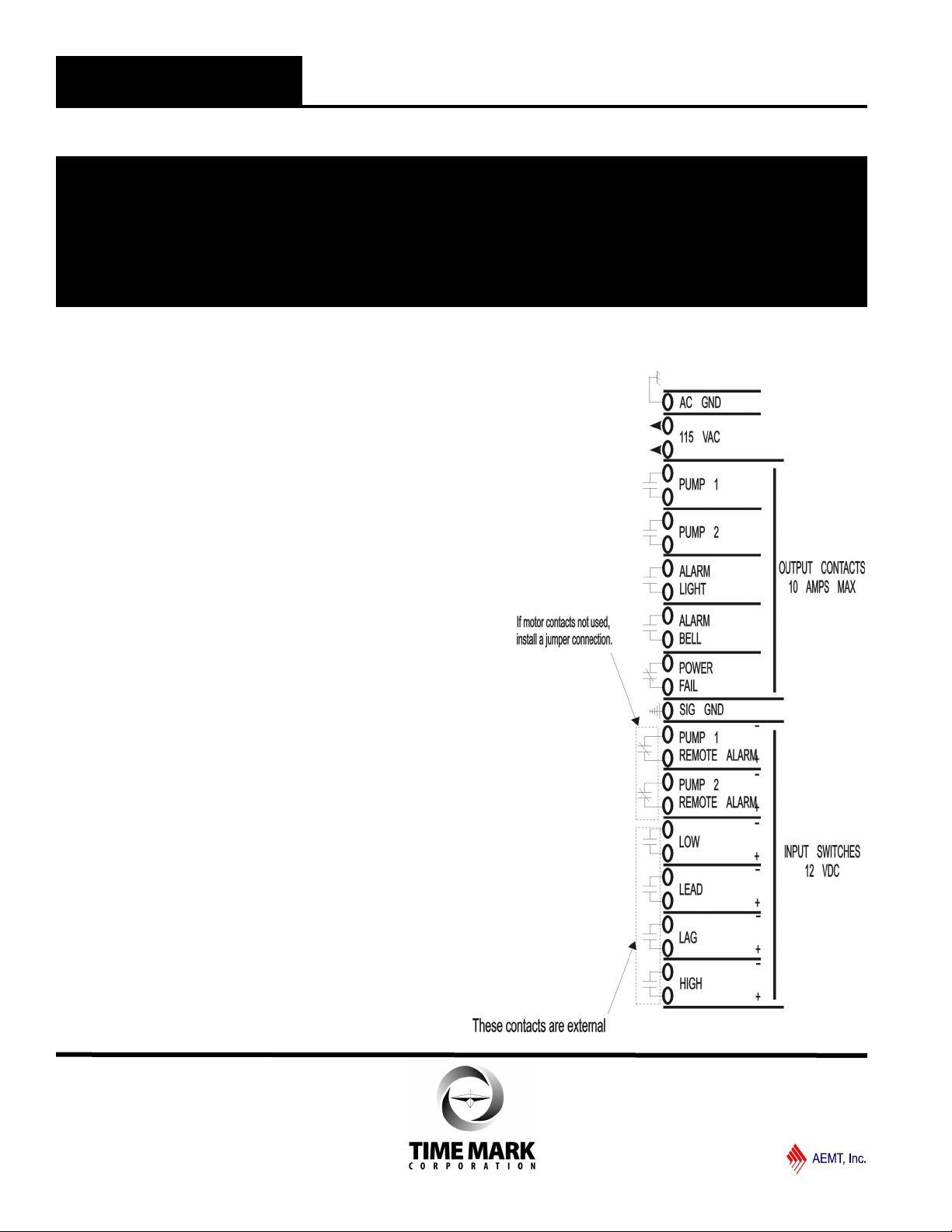
Referring to the terminal block decal on the controller and
the illustration on this page, make the following
connections.
1. Connect a chassis ground to the terminals marked AC
GND.
2. Connect 115VAC operating power to the terminals
marked 115VAC.
3. Connect the LOW float switch to the LOW terminals.
Polarity is not critical.
4. Repeat step 3 for LEAD, LAG and HIGH terminals.
5. The SIGNAL GROUND connection is a common
between the controller, (Model 403), and a Liquid
Level Sensor, ( Model 404), no connection is
necessary if the sensor is not used.
6. The PUMP 1 & 2 REMOTE ALARM terminals should
be connected to normally closed (NC) alarm contacts
in the motors. If none exist it is still necessary to
install a jumper connection between Pump 1 REMOTE
ALARM terminals & PUMP 2 REMOTE ALARM
terminals.
7. The POWER FAIL, ALARM BELL, & ALARM LIGHT
are not required for proper operation, but are provided
for your convenience. If used, connect an a u d i b l e /
visual alarm across the terminals. The POWER FAIL
contact is open while power is applied and closes
on loss of power. Connect audible and v i s u a l
alarms across the ALARM BELL and ALARM L i g h t
terminals respectively. These contacts are
normally open and will close on a fault (high or remote
alarm) condition.
8. Connect the PUMP 1 and the PUMP 2 contacts to the
appropriate motor control circuits. These contacts
start and stop the pump motors during operation.
Set the HOA (Hand-off-Auto) switches and the LEAD
PUMP selector switch as required. Apply operating power.
Test alarm LEDs and bells by pressing the ALARM TEST
switch.
Page 2 of 4 11/2011
© 2011 TIME MARK CORPORATION
Page 3
TIME MAR K is a division of
MODEL 403
Liquid Level Controller
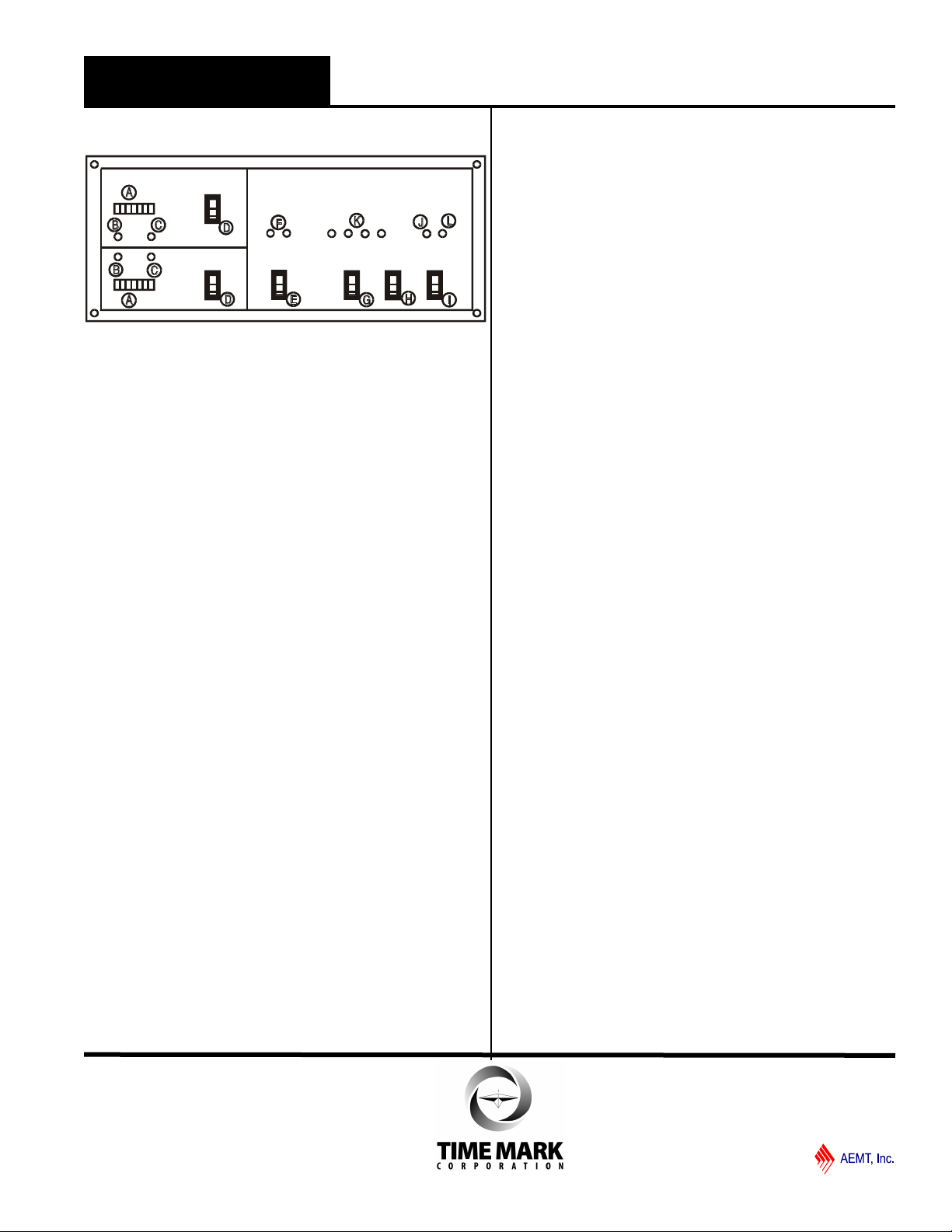
Model 403 Panel
Panel Layout
A. Pump running time meter to 99,999.9 hours, non resettable.
B. Indicator LEDs illuminate when pumps are running.
C. Indicator LEDs illuminate when pump is stopped
because the remote alarm circuit is open.
D. Hand-off-Auto switch to manually or automatically
control the pumps.
E. Lead pump selector switch alternates lead pump
selection or a fixed lead pump operation of pump
1 or 2.
F. Indicator LEDs show which pump is the lead pump
for the next pumping cycle.
G. Momentary switch tests remote alarm bell, light,
and illuminates alarm light J.
H. Momentary switch silences alarm bell until problem
is corrected.
I. Momentary switch resets all alarm indicators to
return to normal operation.
J. Alarm light stays lit until alarm reset switch is
pressed.
K. Indicator LEDs show which level switches are
closed.
L. Indicator LED illuminates when primary power is
applied.
OPERATION
The Liquid Level controller can be used in either pumpdown applications (with sump pumps) or in pump-up
applications (to fill water tanks or reservoirs). The type
of application is determined by the type of level switch
used, normally-open or normally-closed.
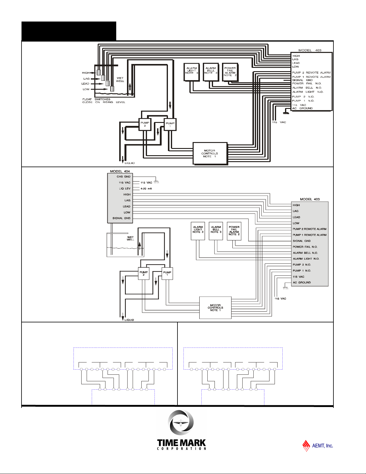
In typical application, as shown on page 4, pumps are
used to remove water from wet well when the water
level activates the float switches. Activating the first
switch (LOW) prepares the controller for operation. No
pump is started. The second level switch (LEAD) starts
the first pump.
Which pump actually starts is determined by the LEAD
PUMP selector switch. The third switch (LAG) starts
the second pump running. The final level switch (HIGH)
illuminates the alarm indicator and closes the alarm bell
and alarm light outputs.
As the level switches are opened (in reverse order) all
operating pumps remain on until the LOW switch is
opened. All pumps are then turned off and the internal
alternator is triggered. On the next operating cycle the
next pump depending which was on before either 1 or 2
will become the lead pump.
If the HIGH level is triggered an alarm light and alarm
bell circuit are activated, plus an LED on the controller
illuminates to warn of the problem.
Should this occur, an ‘Alarm Silence’ switch on the
controller breaks the alarm bell contacts, but leaves the
LED alarm indicator on.
When the alarm condition is corrected, an alarm reset
switch returns the controller to its normal operating
mode.
TROUBLESHOOTING
Problem: Remote alarm LEDs will not extinguish
Causes: 1. Remote alarm inputs not jumpered closed
2. Motor circuit to close jumpers is open
Solutions: 1. Install jumpers
2. Close circuit
Problem: Remote alarm LEDs come on for no apparent
reason and inputs are jumpered closed.
Causes: Externally generated noise. Noise can be
generated from faulty circuit breakers, contacts
and motors. It can also be induced from the
source being too close to the controller with little
or no shielding.
Solutions: Replace faulty components; install noise
suppression devices; shield wiring.
Note: This device is not a field repairable unit. Should the unit not
operate properly during installation or testing, insure that all electrical,
ground, and physical connections are correct. Verify that the proper
voltage is applied and check all fuses. Check all motor control
circuits, and insure that, if the REMOTE ALARM contacts are not
used, they are jumpered. If everything is correct and the device still
fails to operate, contact the factory. Should the controller fail during
use, contact the factory for instructions on returning the device for
repair.
WARRANTY
This product is warranted to be free from defects in materials
and workmanship for one year. Should this device fail to
operate, we will repair it for one year from the date of
manufacture. For complete warranty details, see the Terms and
Conditions of Sales page in the front section of the Time Mark
catalog or contact Time Mark at 1-800-862-2875.
Page 3 of 4 11/2011
© 2011 TIME MARK CORPORATION
Page 4
+ - -+ -+ -+
HIGH LAG LEAD LOW
C NO C NC NCCNOC NCCNOC NCCNOC
4 3 2 1
MODEL 4042
MODEL 403
PUMP DOWN
APPLICATION
SETPOINT 4 > SETPOINT 3 > SETPOINT 2 > SETPOINT 1 SETPOINT 1<SETPOINT 2<SETPOINT 3<SETPOINT 4
APPLICATION
PUMP UP
MODEL 403
MODEL 4042
1234
C NO C NCC NO C NCC NO C NCNCCNOC
LOWLEADLAGHIGH
+ -+ -+ --+
Fig. 3
Model 403 to Model 4042
Fig. 4
Model 403 to Model 4042
TIME MAR K is a division of
MODEL 403
TYPICAL
APPLICATIONS
Fig. 1
Model 403 to float switches
Note:
1. Remote alarm contacts
are normally closed
contacts located at the
motor controllers. Jumper
closed if not used.
2. Power fail contacts close
on power failure.
3. Alarm Bell and Alarm
Light contacts close on
alarm condition.
Fig. 2
Model 403 to Model 404
Liquid Level Controller
Note:
1. Remote alarm contacts are normally
closed contacts located at the motor
controllers. Jumper closed if not
used.
2. Power fail contacts close on power
failure.
3. Alarm Bell and Alarm Light contacts
close on alarm condition.
Page 4 of 4 11/2011
© 2011 TIME MARK CORPORATION
 Loading...