

MODEL 310
2.88”
2.44”
1.75”
3.52”
+
1
3
2
4
5
10
6
7
9
8
11
COIL AC/DC
TIME MARK is a division of
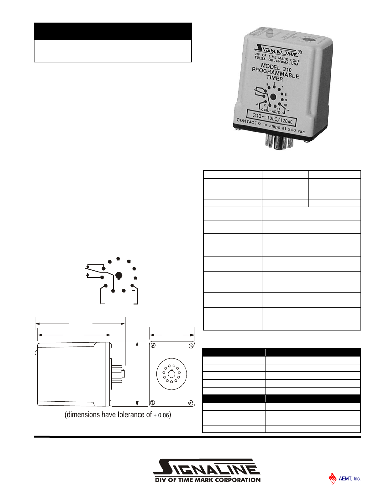
Programmable Timer
Multiple Timing Ranges
5 Function Modes
Digital Timing Circuit
5-Year Unconditional Warranty
DESCRIPTION
The Model 310 Programmable Timer is a universal timer
designed to replace over 20 standard timers. Each Model 310
can be set for one of five functions in four timing ranges, and
is available in two voltage ranges.
The digital design of the Model 310 provides high accuracy
repeatability and response time. The heavy-duty output relay
carries loads up to 10 amps at up to 240 volts AC, resistive.
Programming is accomplished by simply installing jump-er
wires between two or more socket pins. An LED indicator
illuminates when the relay is energized.
PIN DIAGRAM
DIMENSIONS
Shows No Power Applied
SPECIFICATIONS
MODEL 310-24 310-120
Supply Voltage 24V AC/DC 110VDC / 120VAC
Voltage Range (AC) 20-28V
Voltage Range (DC) 20-32VDC 95-125VDC
Functional Modes Interval Timer; Operate Delay
Timing Ranges
Accuracy ± 10% **
Repeatability
Response Time 100ms **
Power Consumption 3W
Contact Rating SPDT 10A at 240VAC resistive
Expected Relay Life Mech: 10 million operations
Operating Temp -4º to +122º F
** @ Ambient Temp 70º F
Humidity Tolerance 0-97% without condensation
Enclosure Material ABS plastic
Mounting 11-pin socket (not included)*
Weight
50/60Hz
Release Delay; Single Shot; Recycle
0.15 to 15 seconds; 0.6 to 60 seconds
5 to 480 seconds; 0.6 to 64 minutes
0.1% **
Elec: 100,000 operations at rated load
4.5 oz.
* order 11-pin socket number 51 X 016
105-130V
50/60Hz
PROGRAMMING
TIME DELAY MODES JUMPER
Interval Timer 2 to 5
Operate Delay 2 to 5, 7 to 10
Release Delay N.O. switch 2 to 6
Single Shot N.O. switch 2 to 5
Recycle 2 to 5, 7 to 10 to 11
TIMING RANGE JUMPER
0.15 to 15 seconds
0.6 to 60 seconds
5 to 480 seconds 8 to 9 to 10
0.6 to 64 minutes
9 to 10
8 to 10
none
11/2011
© 2011 TIME MARK CORPORATION
Outp ut
Supply
Voltage
Delay
Outp ut
Supply
Voltage
Delay
Cont ro l
Switch
Outp ut
Supply
voltage
Delay
Release
Init iate
Outp ut
Supply
Voltage
Delay
Outp ut
Supply
Voltage
T1 T1 T1 T1T2 T2 T2
MODEL 310
TIME MARK is a division of
Programmable Timer
READ ALL INSTRUCTIONS BEFORE INSTALLING, OPERATING OR SERVICING THIS DEVICE.
KEEP THIS DATA SHEET FOR FUTURE REFERENCE.
GENERAL SAFETY
POTENTIALLY HAZARDOUS VOLTAGES ARE PRESENT AT THE TERMINALS OF THE MODEL 310.
All electrical power should be removed when connecting or disconnecting wiring.
This timer and wiring should be installed and serviced by qualified personnel.
Installation Instructions
This diagram refers to RELEASE DELAY function (previous column)
INSTALLATION
Mount the 11-pin socket in a suitable enclosure. Connect the
appropriate operating power to terminals 10 and 2.
Referring to the diagrams below, and the PROGRAMMING
TABLE and PIN DRAWING on the reverse of this sheet,
connect timing and function jumpers to the socket terminals.
Connect the load to the appropriate relay output terminals of
the socket.
Install the timer in the socket.
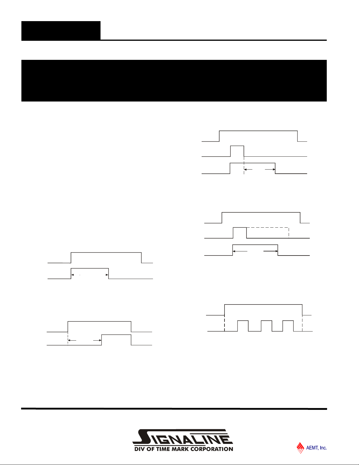
FUNCTION DESCRIPTIONS
INTERVAL TIMER: The output relay energizes when operating power is applied. When the timing period elapses, the
relay de-energizes. The timer is reset by removing and
reapplying power.
OPERATE DELAY: The delay period begins when operating
power is applied. When the timing period elapses, the output
relay energizes. The timer is reset and restarted by removing
and reapplying power.
RELEASE DELAY: Operating power is continuously applied
to the timer. When the external control switch is closed the
output relay energizes. When the control switch is opened the
timing period begins. If the control switch closes before the
timing period elapses, the output relay remains energized and
the timing period is reset. When the timing period elapses, the
output relay de-energizes. The timer is restarted by re-closing
the control switch. Refer to diagram at top of next column
SINGLE SHOT: Operating power is continuously applied to
the timer. When the external control switch is closed the
output relay energizes and the timing period begins.
Regardless of the condition of the control switch, when the
timing period elapses the output relay de-energizes.
* If Switch is re-closed before time has elapsed, timing will restart*
RECYCLE: Operating power is continuously applied to the
timer. When operating power is applied, the OFF delay period
begins. When the OFF delay period elapses, the output relay
energizes, and the ON delay period begins. This cycle repeats
until operating power is removed.
NOTE: For recycle timing ON and OFF times are equal.
WARRANTY
This product is warranted to be free from defects in materials
and workmanship, and is covered by our exclusive 5-year
Unconditional Warranty. Should this device fail to operate
for any reason, we will repair it for five years from the date of
manufacture. For complete warranty details, see the Terms
and Conditions of Sales page in the front section of the Time
Mark catalog or contact Time Mark at 1-800-862-2875.
11/2011
© 2011 TIME MARK CORPORATION
 Loading...