

Page 1
MODEL 300
Programmable Timer
Multiple timing & voltage ranges
Five function modes
Easy to program
5-Year Unconditional Warranty
DESCRIPTION
The Model 300 Programma ble Timer is designed to replace
over 100 standard timers. One Model 300 can be set for one
of five functions, covers four timing ranges, and has a power
supply for any AC/DC voltage from 10 to 28 Volts or 40 to 260
Volts. An “SG” version of this model is available using silver
with gold flash contacts.
The digital design of the Model 300 provides hig h accuracy,
repeatability and response time. The output of the Model 300
is a heavy-duty SPDT electro-mechanical output relay.
Programming options are chosen by simply setting the four
DIP switches on top of the relay, and then adjusting a
potentiometer for percent of delay. A LED indicator
illuminates when the relay is energized.
The Model 300 can be set to Delay-on-Release by adding an
external jumper between pins 6 and 8 (see Installation
Instructions on reverse side).
The Model 300 is UL Recognized and CSA Certified.
UL SPECIFICATIONS*
Models 300
Input
Voltage (VAC)
Power 3 Watts Max
Output
10-28V AC/DC OR 40-260V AC/DC
240V AC, 10A, Resistive
120V AC, 4A, General Use
240V AC, 2A, General Use
* Pilot Duty:
120V: Make 1 5A, Break 1.5A
240V: Make 7.5A, Break 0.75A
C300, Pilot Duty
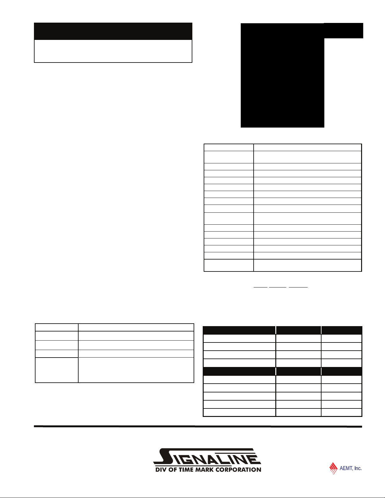
SPECIFICATIONS
MODEL 300
Voltage L = 10-28V AC/DC
Timing Range 0.15 seconds to 64 minutes
Accuracy ±5%
Repeatability 0.1%
Response time 100ms
Contacts SPDT
Contact rating 10A at 240VAC resistive
Transient protection 775V, 80 Joules
Expected relay life Mechanical: 10 million operations
Operating temperature -20º to +140º F
Humidity tolerance 0-97% without condensation
Case material NORYL Plastic
Mounting
Weight 4.5 oz.
Additional Options /C = Custom (Voltage and/or Timing)
Ordering Examples (Model-Voltage [/Options]):
300-H = Model 300 with a 40-260V AC/DC voltage range
300-L /SG = Model 300 with a 10-28V AC/DC voltage range and
optional silver with gold flash contacts.
Contact Time Mark to order a custom programmed unit
Electrical: 100,000 operations at rated load
** order 8-pin socket number 51 x 120
H = 40-260V AC/DC
8-pin socket (not included)**
/SG = Silver with Gold Flash Contacts
PROGRAMMING
TIMING RANGE SWITCH 1 SWITCH 2
0.15 to 15 seconds
0.6 to 60 seconds
5 to 480 seconds ON ON
0.6 to 64 minutes
FUNCTIONS SWITCH 3 SWITCH 4
Interval-on-Operate ON OFF
Delay-on-Operate ON ON
Delay-on-Release* ON OFF
Recycle Start-ON OFF OFF
Recycle Start-OFF OFF ON
* For Delay on Release—See Installation Instructions on reverse side.
OFF ON
ON OFF
OFF OFF
© 2014
TIME MARK is a division of
05/2014
TIME MARK CORPORATION
Page 2
MODEL 300
Programmable Timer
READ ALL INSTRUCTIONS BEFORE INSTALLING, OPERATING OR SERVICING THIS DEVICE.
KEEP THIS DATA SHEET FOR FUTURE REFERENCE.
GENERAL SAFETY
POTENTIALLY HAZARDOUS VOLTAGES ARE PRESENT AT THE TERMINALS OF THE MODEL 300.
ALL ELECTRICAL POWER SHOULD BE REMOVED WHEN CONNECTING OR DISCONNECTING WIRING.
THIS DEVICE SHOULD BE INSTALLED AND SERVICED BY QUALIFIED PERSONNEL.
Installation Instructions
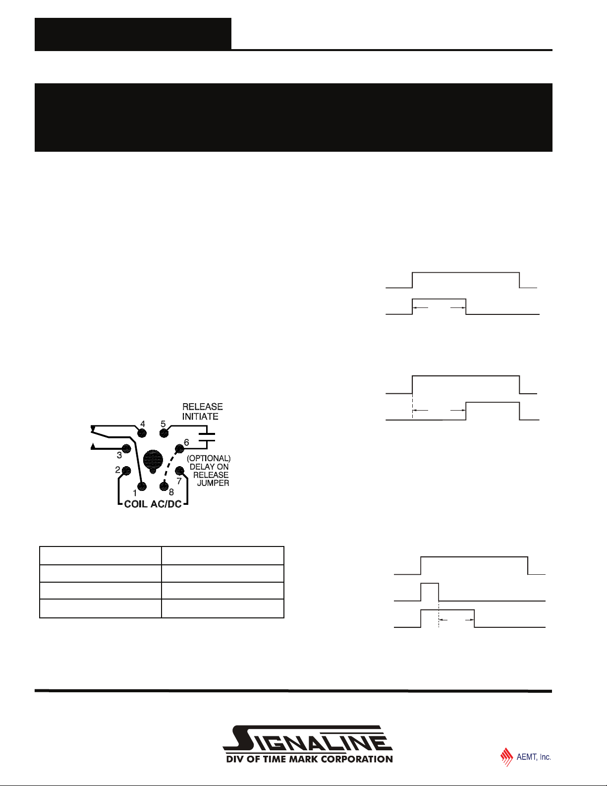
INSTALLATION
1. Mount the 8-pin socket in a suitable enclosure.
2. Referring to the PROGRAMMING table on the reverse
side of this sheet and PIN CONNECTIONS diagram
below, set the DIP switches for desired function and
timing range.
3. Connect the load to the appropriate relay output
terminals of the socket.
4. For the Delay-on-Release function, install a normally
open switch on terminals 5 and 6 of the socket and add
an external jumper between pins 6 and 8 (shown as a
dashed line in Pin Connections diagram below).
5. Connect the appropriate operating power to terminals 7
and 2.
PIN CONNECTIONS
An LED on top of the unit provides a quick visual indicator of
the relay’s status.
LED Indicator Unit Status
Green Energized
FUNCTION DESCRIPTIONS
Interval-on-Operate: The output relay energizes when op-
erating power is applied. When the timing period elapses, the
relay de-energizes. The timer is reset by removing and
reapplying power.
Supply voltage
Output
Delay
Delay-on-Operate: The delay period begins when operating
power is applied. When the timing period elapses, the output
relay energizes. The timer is reset and restarted by removing
and reapplying power.
Supply voltage
Delay-on-Release: Operating power is continuously applied to
the timer. When the external release initiate switch is closed
the output relay energizes. When the control switch is
opened the timing period begins. If the control switch closes
before the timing period elapses, the output relay remains
energized and the timing period is reset. When the timing
period elapses, the output relay de-energizes. The timer is
restarted by re-closing the control switch.
For the Delay on Release function, you must add an external
jumper between pins 6 and 8.
Output
Delay
Supply voltage
Red De-energized
Flashing (Green or Red) Relay is Timing
Release initiate
Output
Delay
Page 2 of 3 05/2014
© 2014
TIME MARK is a division of
TIME MARK CORPORATION
Page 3

MODEL 300
Programmable Timer
READ ALL INSTRUCTIONS BEFORE INSTALLING, OPERATING OR SERVICING THIS DEVICE.
KEEP THIS DATA SHEET FOR FUTURE REFERENCE.
GENERAL SAFETY
POTENTIALLY HAZARDOUS VOLTAGES ARE PRESENT AT THE TERMINALS OF THE MODEL 300.
ALL ELECTRICAL POWER SHOULD BE REMOVED WHEN CONNECTING OR DISCONNECTING WIRING.
THIS DEVICE SHOULD BE INSTALLED AND SERVICED BY QUALIFIED PERSONNEL.
Installation Instructions
Recycle Start-ON: Operating power is continuously applied
to the timer. When operating power is applied, the ON delay
period begins. When the ON delay period elapses, the output
relay de-energizes, and the OFF delay period begins. This
cycle repeats until operating power is removed.
Supply voltage
Output
Recycle Start-OFF - Operating power is continuously applied
to the timer. When operating power is applied, the OFF delay
period begins. When the OFF delay period elapses, the
output relay energizes, and the ON delay period begins. This
cycle repeats until operating power is removed.
Supply voltage
T1 T2 T1 T1 T1T2 T2
Output
T1 T2 T1 T1 T1T2 T2
NOTE: For recycle timing ON and Off times are equal.
WARRANTY
This product is warranted to be free from defects in materials
and workmanship, and is covered by our exclusive 5-year
Unconditional Warranty. Should this device fail to operate
for any reason, we will repair it for five years from the date of
manufacture. For complete warranty details, see the Terms
and Conditions of Sales page in the front se ction of the Time
Mark catalog or contact Time Mark at 1-800-862-2875.
DIMENSIONS
Shows No Power Applied
Page 3 of 3 05/2014
© 2014
TIME MARK is a division of
TIME MARK CORPORATION
Page 4

Have Questions? Call us at (800) 862-2875 and talk to a real live person.
© 2014
TIME MARK is a division of
05/2014
TIME MARK CORPORATION
 Loading...