

TIME MARK is a division of
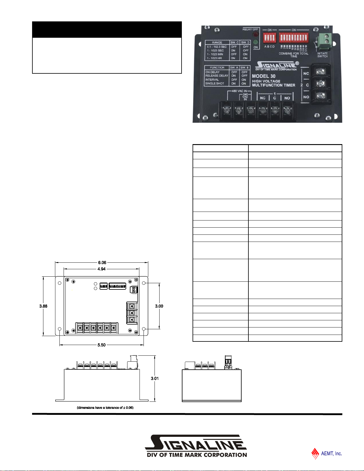
MODEL 30
High Voltage
Multi-function Timer
⚫ 600VAC Contacts
⚫ 240/480VAC Operating Voltage
⚫ 4 Timing Functions
⚫ 4 Timing Ranges
DESCRIPTION
The Model 30 is a High Voltage Multifunction Timer.
The digital design of the Model 30 provides high accuracy,
repeatability and response time. The output of the Model 30 is
a heavy-duty DPDT electro-mechanical output relay.
Four DIP switches select one of four timing functions and one
of four timing ranges. Delay time is set with a 10-position DIP
switch. When timing either the red LED will blink indicating the
relay is de-energized or the green LED will blink indicating the
relay is energized. On completion of the delay period either
the red LED lights indicating the relay is de-energized or the
green LED lights indicating the relay is energized.
DIMENSIONS
SPECIFICATIONS
MODEL 30
Voltage 240/480VAC Single Phase
Power Consumption 3.7W
Frequency 50/60 Hz
Timing Ranges
Accuracy
Repeatability ± 0.1%
Reset Time 1 Sec for On Delay and Interval
Initiate Switch Input 5V Open Circuit / 500µa Short Circuit
Contacts DPDT
N.O. Contact Rating
N.C. Contact Rating
Expected Relay Life
Frequency of Operation 360 Operations/Hr
Operating Temperature -20 to +140º F
Humidity Tolerance 0 – 97% w/o Condensation
Case Material Noryl
Mounting Surface Mount
Weight 1 lb 1 oz
Mechanical: 10,000,000 Operations
Electrical: 100,000 Operations at Rated
0.1 – 102.3 Sec
1 – 1023 Sec
1 – 1023 Min
1 – 1023 Hr
± 2% of Time Delay Setting
± 0.025 Sec
10A, 600VAC General Purpose
1.5Hp, 480VAC or 600VAC
0.5A, 12VAC Minimum
3A, 277VAC
2A, 480VAC
1A, 600VAC
0.1A, 12VAC Minimum
Load
11440 East Pin e St r eet
Tul s a, O k lah o ma 7 411 6
07/2018
© 2018 TIME MARK CORPORATION
TIME MARK is a division of
MODEL 30
High Voltage Multi-function Timer
READ ALL INSTRUCTIONS BEFORE INSTALLING, OPERATING OR SERVICING THIS DEVICE.
KEEP THIS DATA SHEET FOR FUTURE REFERENCE.
GENERAL SAFETY
POTENTIALLY HAZARDOUS VOLTAGES ARE PRESENT AT THE TERMINALS OF THE MODEL 30.
ALL ELECTRICAL POWER SHOULD BE REMOVED WHEN CONNECTING OR DISCONNECTING WIRING.
THIS DEVICE SHOULD BE INSTALLED AND SERVICED BY QUALIFIED PERSONNEL.
Installation Instructions
INSTALLATION
1. Mount the Model 30 to the back panel of a suitable
enclosure (mounting hardware is not included).
2. Set the DIP switches for the desired timing range and
function as shown in the PROGRAMMING table .
3. Set the DIP switches for the delay time as shown in the
ADJUSTMENT PROCEDURE.
4. Connect the load to the appropriate relay output
terminals.
5. For the Release Delay and Single Shot function, install a
normally open switch to the green 2-position plug.
6. Connect operating power to the appropriate terminals of
the 6-position terminal strip. Refer to drawing below.
*We recommend a 1A 600VAC Fuse on input
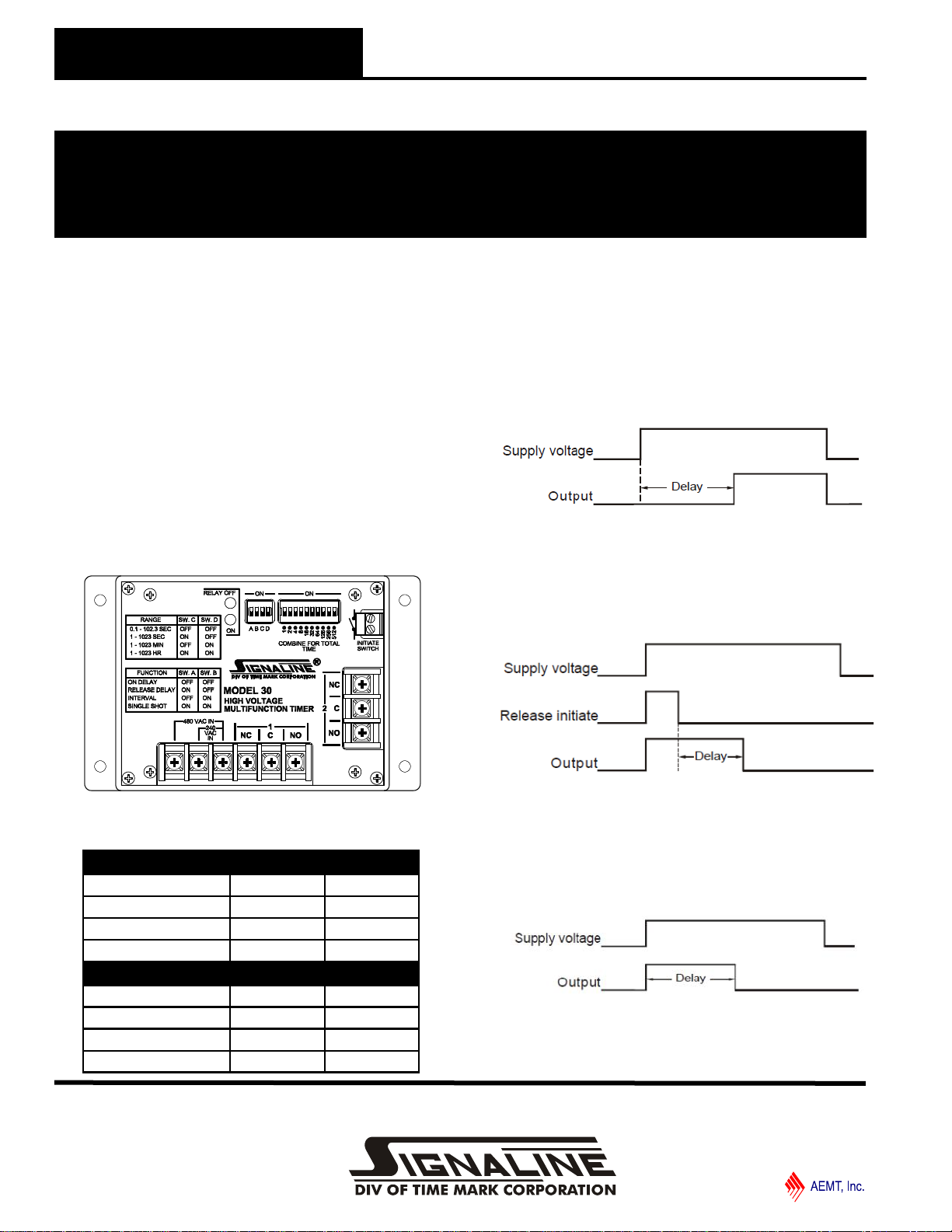
FUNCTION DESCRIPTIONS
On Delay: The time delay begins when the supply voltage is
applied. Upon completion of the delay period, the internal relay
will energize, and remain that way until the supply voltage is
removed.
Release Delay: Supply voltage must be constantly applied.
When the control switch is closed, the internal relay will
energize. Timing begins when the control switch is opened.
The delay can be reset by re-closing the control switch. On
completion of the delay, the relay will de-energize.
PROGRAMMING (4-Position DIP Switch)
FUNCTION SWITCH A SWITCH B
ON DELAY OFF OFF
RELEASE DELAY ON OFF
INTERVAL OFF ON
SINGLE SHOT ON ON
TIMING RANGE SWITCH C SWITCH D
0.1 - 102.3 SEC OFF OFF
1 - 1023 SEC ON OFF
1 - 1023 MIN OFF ON
1 - 1023 HR ON ON
Interval: The internal relay energizes immediately on
application of the supply voltage. Upon completion of the delay
period, the relay de-energizes. The supply voltage must be
removed to reset the timer.
11440 East Pin e St r eet
Tul s a, O k lah o ma 7 411 6
Page 2 of 3 07/2018
© 2018 TIME MARK CORPORATION

124 ⚫
8
16
32 ⚫
64 ⚫
128
256
512
Code:⚫= switch ON
= switch OFF
124
8 ⚫
16
32 ⚫
64 ⚫
128 ⚫
256 ⚫
512 ⚫
Code:⚫= switch ON
= switch OFF
TIME MARK is a division of
MODEL 30
High Voltage Multi-function Timer
READ ALL INSTRUCTIONS BEFORE INSTALLING, OPERATING OR SERVICING THIS DEVICE.
KEEP THIS DATA SHEET FOR FUTURE REFERENCE.
GENERAL SAFETY
POTENTIALLY HAZARDOUS VOLTAGES ARE PRESENT AT THE TERMINALS OF THE MODEL 30.
ALL ELECTRICAL POWER SHOULD BE REMOVED WHEN CONNECTING OR DISCONNECTING WIRING.
THIS DEVICE SHOULD BE INSTALLED AND SERVICED BY QUALIFIED PERSONNEL.
Installation Instructions
FUNCTION DESCRIPTIONS (cont’d)
Single Shot (Re-Triggerable): With power applied to the
coil, the relay will energize for the time period set by the user
when the initiate switch (dry contact) is closed. At the end of
the preset time period, the relay will de-energize. If the initiate
switch opens and then closes multiple times while the relay is
energized (i.e. it is “retriggered”), the relay will then restart the
delay time. The relay will remain energized until the
retriggering stops and the delay time ends. When power is
removed, the relay will de-energize.
RELAY STATUS
LED INDICATOR UNIT STATUS
GREEN ENERGIZED
RED DE-ENERGIZED
FLASHING (GREEN OR RED) RELAY IS TIMING
ADJUSTMENT PROCEDURE
The procedure to set the delay time requires some simple
calculations, which can be completed easily after the basic
steps are explained.
1. Convert the delay time required to hours, minutes,
seconds, or tenths of seconds, depending upon the timing
range selected.
ADJUSTMENT PROCEDURE
For example:
7 hrs, 32 min = (7x60)+32 = 452 minutes
(Select timing range 1 - 1023 min)
15 min, 2 secs = (15x60)+2 = 902 seconds
(Select timing range 1 - 1023 sec)
6.7 secs = (6.7*10) = 67 tenths of a second
(Select timing range 0.1 - 102.3 sec)
2. To set the desired delay period on the timer, just add the
values of the selected dip switches (beginning with the largest
value first) to total the desired time.
e.g. #1: 100 seconds with a 1 second increment
64 + 32 + 4 = 100 seconds.
e.g. #2: 100 seconds with a 0.1 second increment
512 + 256 + 128 + 64 + 32 + 8 = 1000 tenths of a second.
WARRANTY
This product is warranted to be free from defects in materials
and workmanship, and is covered by our exclusive 5-year
Unconditional Warranty. Should this device fail to operate
for any reason, we will repair it for five years from the date of
manufacture. For complete warranty details, see the Terms
and Conditions of Sales page in the front section of the Time
Mark catalog or contact Time Mark at 1-800-862-2875.
11440 East Pin e St r eet
Tul s a, O k lah o ma 7 411 6
Page 2 of 3 07/2018
© 2018 TIME MARK CORPORATION

TIME MARK is a division of
Have Questions? Call us at (800) 862-2875 and talk to a real live person.
1144 0 Ea s t P i ne S tree t
Tul s a, O k lah o ma 7 411 6
07/2018
© 2018 TIME MARK CORPORATION
 Loading...