

Page 1
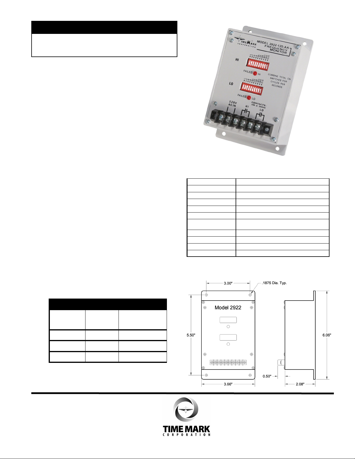
MODEL 2922
Frequency Monitor
Monitors over and/or under frequency
Automatic reset
Solid-state electronic circuitry
DESCRIPTION
The Model 2922 Frequency Monitor is designed to
monitor power line frequency. It is intended for systems
where line frequency variations will cause improper
operation of electrical equipment.
A solid-state sensing circuit drives two internal
electromechanical relays. One relay is energized when
the line frequency is high and the other relay is
energized when the line frequency is low. Operating
power is drawn from the same line being monitored.
The Model 2922 is set to the over and/or under
frequency trip points using ten binary-coded switches.
A frequency variation outside the trip points causes the
appropriate relay to energize and an appropriate LED
indicator to illuminate.
Applications for the Model 2922 include standby power
plants, portable power supplies, and windmill
generators.
ORDERING:
Model Nominal
(VAC)
Operating
Voltage
2922-24 24 20 - 30
SPECIFICATIONS
Model
Input Voltage XXX = 24, 120 or 240
Operating Frequency 45-1023 Hz
Response Time 1 second
Transient Protection 2500 V for 10 msec
Contact Rating SPDT x 2 10 amps at 240VAC resistive
Expected Relay Life Mech: 10 million operations
Operating Temp - 20° to +122° F
Humidity Tolerance 0-97% w/o condensation
Enclosure Material ABS plastic
Weight 12 oz. Max.
2922-XXX
Elec: 100,000 at rated load
DIMENSIONS
2922-120 120 90 - 130
2922-240 240 190 - 240
Page 2
MODEL 2922
1
2
4
8
163264
128
256
512
1
2
4
8
16
32
64
128
256
5
12
HI
Switch ON
Switch OFF
1
2
4
8
163264
128
256
512
1
2
4
8
16
32
64
128
256
5
12
HI
Switch ON
Switch OFF
Model 2922
L1
LOAD
M
LO FREQUENCY
CONTROL
HI FREQUENCY
CONTROL
L2
A
C
H
I
L
O
Frequency Monitor
READ ALL INSTRUCTIONS BEFORE INSTALLING, OPERATING OR SERVICING THIS DEVICE.
KEEP THIS DATA SHEET FOR FUTURE REFERENCE.
GENERAL SAFETY
POTENTIALLY HAZARDOUS VOLTAGES ARE PRESENT AT THE TERMINALS OF THE MODEL 2922.
ALL ELECTRICAL POWER SHOULD BE REMOVED WHEN CONNECTING OR DISCONNECTING WIRING.
THIS DEVICE SHOULD BE INSTALLED AND SERVICED BY QUALIFIED PERSONNEL.
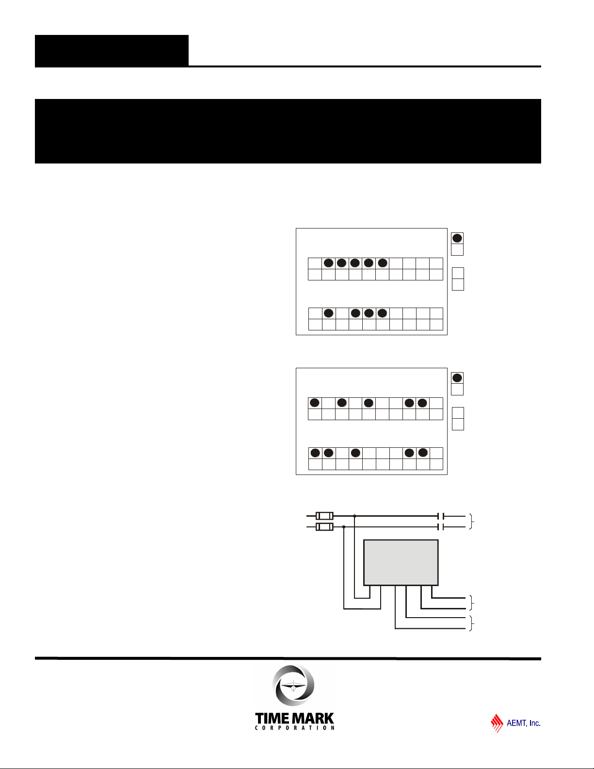
Installation Instructions
INSTALLATION
Connect the control wiring to the terminals with the
contact markings (refer to the diagram on the unit).
Apply power.
TROUBLESHOOTING
Should the Model 2922 Frequency Monitor fail to
operate, check all connections. Verify that power is
present, and check all fuses. Should problems persist,
contact the factory at 800-862-2875 for assistance.
OPERATION
To select a frequency trip point, set the appropriate
switches to ON. Figure 1 shows the Model 2922 set
to trip at frequencies below 58 Hz and above 62 Hz.
Figure 2 shows the Model 2922 set for a frequency
band of 400 Hz +/-5 Hz.
WARRANTY
The Model 2922 Frequency Monitor is warranted to
be free from defects in materials and workmanship for
one year. Should this device fail to operate, we will
repair or replace it for one year from the date of
purchase. For complete warranty details, see the
Terms and Conditions of Sales page in the front section
of the Time Mark catalog.
Figure 1
Figure 2
TYPICAL APPLICATION
Shows No Power Applied
 Loading...