

Page 1
2
3
4
5
6
7
8
1
1
2
3
4
5
6
7
8
0-5 amps
0-5 amps
To current monitor
From CT
Use 14 ga. Wire minimum
Keep as short as possible.
1000 ft. Using 22 ga.
CONNECTION DIAGRAM
TIME MARK is a division of
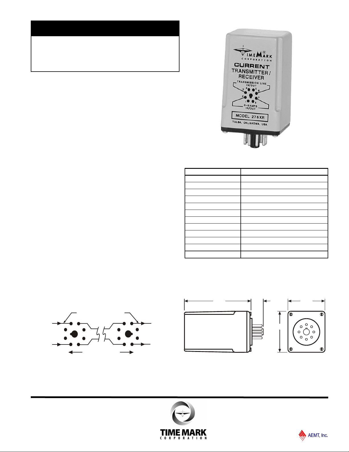
MODEL 276XR
3.25" 0.65"
1.95"
1.95"
Current
Transmitter/Receiver
Allows longer transmission lines
from CT to current monitor
No external power required
Convenient socket mounting
Five year unconditional warranty
DESCRIPTION
The Model 276XR Current Transmitter/Receiver
consists of two identical modules. One module accepts
the input from a standard CT, while the second module
is connected to a current monitor. The transmission
lines between the two modules can be up to 1000 feet
long.
The input module will accept any current input from zero
to 5 amps, while the output module will produce a zero
to 5 amp signal. Line loss across 1000 feet is no more
than 6% of the input. The Model 276XR module will
operate with any AC current from 50 to 400 Hz. No
supply voltage is required to operate the transmitter/
receiver link.
TYPICAL APPLICATION
SPECIFICATIONS
Model 276XR
Supply voltage none required
Input current Zero to 5 amps
Output current Zero to 5 amps
Frequency range 50-400 Hz
Max. line loss 6%
In/out line 14 ga. wire
Transmission line 22 ga. wire
Transmission line length 1000 feet
Operating temperature - 20° to +131° F
Humidity tolerance 0-97% w/o condensation
Mounting 8-pin socket (*order separately)
Weight (each)
*order 8-pin socket number 51X120
4.9 oz.
DIMENSIONS
© 2012 TIME MARK CORPORATION
01/2012
Page 2
2
3
4
5
6
7
8
1
1
2
3
4
5
6
7
8
0-5 amps
0-5 amps
To current monitor
From CT
Use 14 ga. Wire minimum
Keep as short as possible.
1000 ft. Using 22 ga.
CONNECTION DIAGRAM
TIME MARK is a division of
MODEL 276XR
Current Transmitter/Receiver
READ ALL INSTRUCTIONS BEFORE INSTALLING, OPERATING OR SERVICING THIS DEVICE.
KEEP THIS DATA SHEET FOR FUTURE REFERENCE.
GENERAL SAFETY
POTENTIALLY HAZARDOUS VOLTAGES ARE PRESENT AT THE TERMINALS OF THE MODEL 276XR.
ALL ELECTRICAL POWER SHOULD BE REMOVED WHEN CONNECTING OR DISCONNECTING WIRING.
THIS DEVICE SHOULD BE INSTALLED AND SERVICED BY QUALIFIED PERSONNEL.
Installation Instructions
INSTALLATION
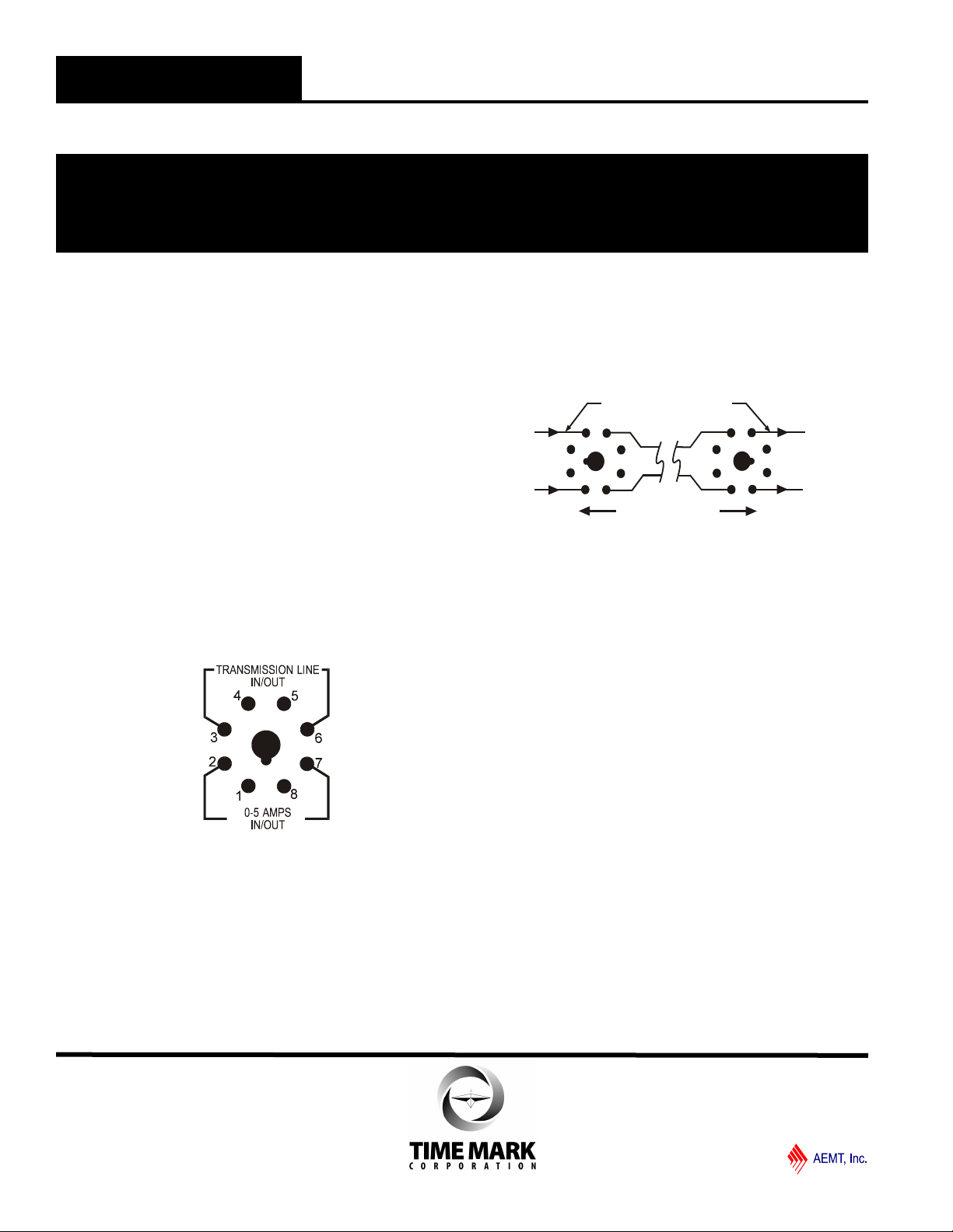
1. Place the two Model 276XR’s next to each other
with one of the models turned 180° so that it is
facing opposite the other.
2. Connect the two transmitter/receivers (CTR’s)
together using 22 gauge wire, as shown in the
diagram on the front of the page.
3. Using 14 gauge wire, connect pins 2 and 7 of one
of the CTR’s to the current transformer (CT) to be
used.
4. Connect the other CTR to your current monitor
with 14 gauge wire.
PIN CONNECTION
TYPICAL APPLICATION
TROUBLESHOOTING
Should these units fail to operate properly check to
make sure that all wires are connected properly to the
correct pins as shown on the front page.If problems still
persist, contact your local Distributor, or the
manufacturer at 800-862-2875.
WARRANTY
This product is warranted to be free from defects in
materials and workmanship, and is covered by our
exclusive 5-year Unconditional Warranty. Should
this device fail to operate for any reason, we will repair
it for five years from the date of manufacture. For
complete warranty details, see the Terms and
Conditions of Sales page in the front section of the
Time Mark catalog or contact Time Mark at 1-800-862-
2875.
© 2012 TIME MARK CORPORATION
01/2012
 Loading...