

Page 1
2.25"
4-40
studs
typ.
4.75"
2.5"
3.9"
2.0"
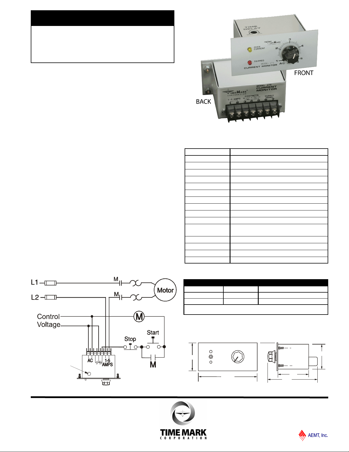
MODEL 275
TIME MARK is a division of
Trip Delay
Adjust
Single Phase
Current Monitor
Panel mounted
Auto or manual reset
Over current and tripped indicators
Matches standard current transfomers
SPECIFICATIONS
DESCRIPTION
The Model 275 Single Phase Current Monitor is
designed for monitoring alternating current in the range of 1
-5 amps, at 50 to 400Hz. The Model 275 provides a
contact transfer when the set current level is exceeded for
a period longer than the time delay. The OVER-CURRENT
indicator illuminates immediately. After the time delay, the
TRIPPED indicator lights and the relay contact transfers.
This device can directly monitor AC currents in the range of
1 to 5 amps; 50-400Hz. Matching transformers are
available to extend the use of this monitor to most any
current range.
The Model 275 is available with automatic or manual reset.
Operating power is supplied by separate 24 or 120 volt
power supply.
TYPICAL APPLICATION
MODEL 275
Supply voltage 120VAC or 24VAC
Power consumption 1 watt max.
Transient protection 2500V for 10ms
Frequency range 50-400Hz
Current range 1-5 amps
Trip delay range
Repeat accuracy 1% max.
Dead band 1% max
Contact Rating SPDT 10A at 240VAC resistive
Operating temp - 20º to +131º F
Expected relay life Mech: 10 million operations
Elec: 100,000 ops at rated load
Reset Automatic or Manual
Humidity tolerance 0-97% without condensation
Case material 20 Gauge CRS
Weight
adjustable 0.2 - 20 sec
11.5 oz.
Shows No Power Applied
O R D ER I N G O P T I O NS
MODEL VOLTS RESET
275-5 24VAC Auto
120VAC Manual
EXAMPLE: 275-5-120-A orders a Model 275 1-5 amps
120VAC automatic reset current monitor.
DIMENSIONS
11/2011
© 2011 TIME MARK CORPORATION
Page 2

MODEL 275
TIME MARK is a division of
Single Phase Current Monitor
READ ALL INSTRUCTIONS BEFORE INSTALLING, OPERATING OR SERVICING THIS
DEVICE.
KEEP THIS DATA SHEET FOR FUTURE REFERENCE.
GENERAL SAFETY
POTENTIALLY HAZARDOUS VOLTAGES ARE PRESENT AT THE TERMINALS OF THE
MODEL 275. ALL ELECTRICAL POWER SHOULD BE REMOVED WHEN CONNECTING
OR DISCONNECTING WIRING. THIS DEVICE SHOULD BE INSTALLED AND SERVICED
BY QUALIFIED PERSONNEL.
Installation Instructions
INSTALLATION
Connect the AC power and the control wiring to the
terminals with the appropriate markings (refer to
the diagram on the unit). For applications in the
1 to 5 amp range make the connections directly to
the motor to be monitored. For applications over
5 amps, Time Mark can supply a matching
transformer to extend the use of this monitor to
most any current range. Apply power.
ADJUSTMENT
Set the trip delay to the required amount of delay.
If the desired AC amps trip level is known, set the
AC AMPS adjustment to that point. A slight
adjustment up or down may be necessary to allow
for tolerance variations.
NOTE: If manual reset is used, press and hold
the reset button during this next step.
Usually a trip is desired only if the current
changes from the present nominal. For
calibration, turn the TRIP DELAY to maximum.
ADJUSTMENT - continued
Turn the AC AMPS adjustment slowly down, until
the yellow TRIPPED indicator lights. Turn the AC
AMPS adjustment back until the light just goes out.
Reset the TRIP DELAY to the previous setting.
TROUBLESHOOTING
Should the Model 275 Single Phase Current Monitor
fail to operate, check all connections. Verify that
power is present, and check all fuses. Should
problems persist, contact the factory at 800-8622875 for assistance.
WARRANTY
This product is warranted to be free from defects
in materials and workmanship for one year.
Should this device fail to operate, we will repair it
for one year from the date of manufacture. For
complete warranty details, see the Terms and
Conditions of Sales page in the front section of the
Time Mark catalog or contact Time Mark at 1-800862-2875.
11/2011
© 2011 TIME MARK CORPORATION
 Loading...