

Page 1
3.5
3.125
4.5
2.25
4.8
4.0
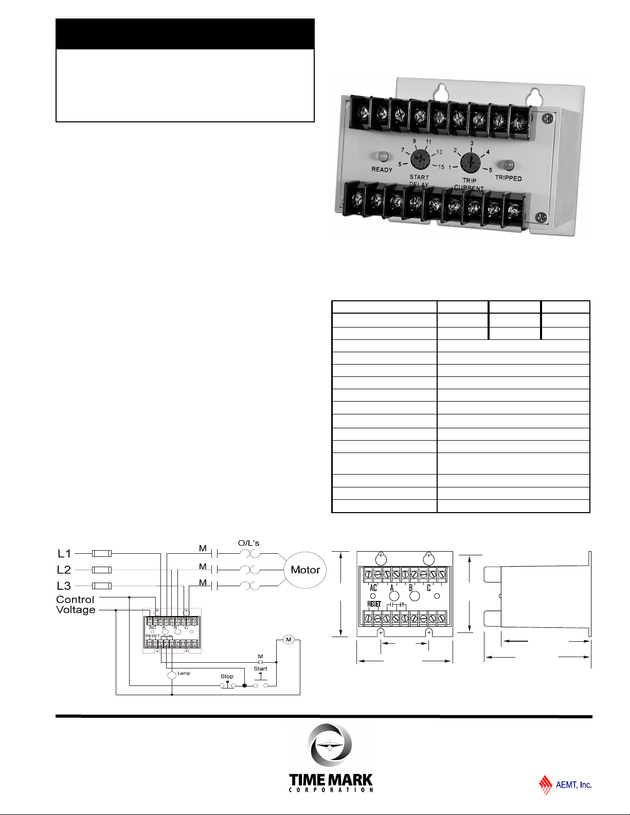
MODEL 2744
TIME MARK is a division of
3-Phase Over Current
Monitor
For Motor Jams
Monitors over current
Fail-safe design
Automatic or manual reset
Adjustable start delay timer
For use on motors, pumps, conveyors, etc.
DESCRIPTION
The Model 2744 3-Phase Over Current Monitor is designed
to monitor the current level of a three-phase line or to compare
the currents of three single-phase lines.
If one or more current inputs rises above the trip level after the
start delay has expired, the internal relay will de-energize.
An adjustable start delay of 5 to 15 seconds will prevent
nuisance tripping on start up. The current trip point is
adjustable from 1 to 5 amps, and matching current
transformers are available to extend the current range of the
monitor.
The Model 2744 will automatically reset when the current fault
is corrected. An external manual reset can be added by
installing a normally closed switch between the terminals
marked RESET.
TYPICAL APPLICATION
Over-current; auto reset; 5 amps
SPECIFICATIONS
Model 2744-24 2744-120 2744-220
Supply voltage 20-28VAC 100-130VAC 190-250VAC
Max supply voltage 30V 140V 260V
Power consumption 1.5 Watts max.
Transient protection 2500 VRMS for 10ms
Frequency range 50 - 400Hz
Input current 1-5 amps ±5%
Max. input current 40 amps for 2 sec
Current range 1-5 amps ± 5%
Start delay 5 to 15 sec ± 5%
Dead band 4% max.
Contact rating SPDT 10A at 240VAC resistive
Expected relay life
Operating temperature - 20º to +131º F
Enclosure material ABS plastic
Weight
Mech: 10 million operations
Elec: 100,000 ops at rated load
1 lb. 5.9 oz.
DIMENSIONS
Shows No Power Applied
11/2011
© 2011 TIME MARK CORPORATION
Page 2
C
B
A
AC
RST
Reset
MANUAL RESET
MODEL 2744
TIME MARK is a division of
3-Phase Over Current Monitor
READ ALL INSTRUCTIONS BEFORE INSTALLING, OPERATING OR SERVICING THIS DEVICE.
KEEP THIS DATA SHEET FOR FUTURE REFERENCE.
GENERAL SAFETY
POTENTIALLY HAZARDOUS VOLTAGES ARE PRESENT AT THE TERMINALS OF THE MODEL 2744.
ALL ELECTRICAL POWER SHOULD BE REMOVED WHEN CONNECTING OR DISCONNECTING WIRING.
THIS DEVICE SHOULD BE INSTALLED AND SERVICED BY QUALIFIED PERSONNEL.
Installation Instructions
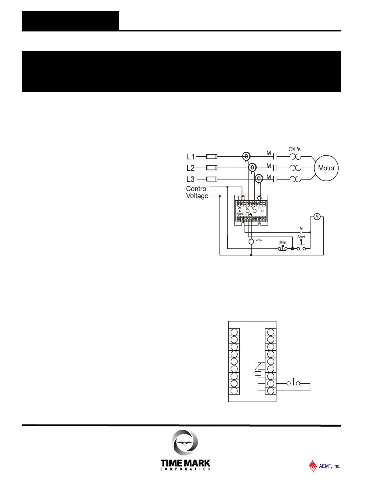
INSTALLATION
Mount the Model 2744 in a suitable enclosure.
If the current to be monitored is 5 amps or less, break and
connect each wire to the three inputs of the Model 2744 (see
TYPICAL APPLICATION on front page). Observe polarity.
If the current to be monitored is greater than 5 amps,
install a current transformer on the line. Connect the
secondary leads of the CT to the Model 2744 terminals (see
TYPICAL APPLICATION on this page). Observe polarity.
Connect the operating supply voltage to the AC input
terminals.
Connect the load control wiring to the appropriate terminals.
For most motor control applications, use the normally open
contact(s), which will close when the current is within the
acceptable range. For alarm applications, use the normally
closed contact(s). Refer to the diagram on this page.
If a manual reset is desired, connect a normally closed push
-button across the RESET terminals (see figure 1).
ADJUSTMENT PROCEDURE
Set the START DELAY adjustment to the required setting. If
the desired current trip level is known, set the CURRENT
adjustment to that point. A slight adjustment up or down may
be necessary to allow for tolerance inaccuracies.
TYPICAL APPLICATION
Over-current; auto reset; 5 amps
Shows No Power Applied
figure 1
WARRANTY
This product is warranted to be free from defects in materials
and workmanship for one year. Should this device fail to operate, we will repair it for one year from the date of manufacture.
For complete warranty details, see the Terms and Conditions of
Sales page in the front section of the Time Mark catalog or contact Time Mark at 1-800-862-2875.
11/2011
© 2011 TIME MARK CORPORATION
 Loading...