

Page 1
2.08"
.47"
5.5"
3.0"
3.88"
6.06"
.203 dia. typ.
A B C
AC
MODEL 274
M
O/L's
Control
Voltage
M
M
L2
L3
L1
M
600 Volts Max.
AC
M
Start
Stop
Motor
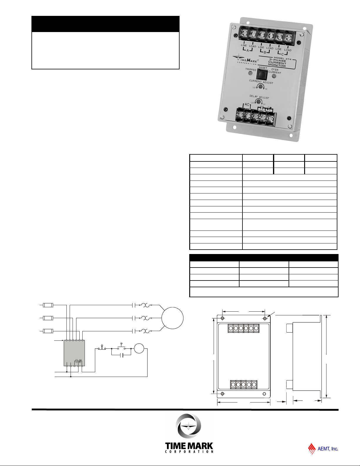
Model
274
TIME MARK is a division of
3-Phase
Current Monitor
Monitors 3 Simultaneous Currents
1 to 5 Amps per Leg
Adjustable Trip for Highest Current
DESCRIPTION
The Model 274 3-Phase Current Monitor is designed
to monitor all legs of a 3-phase line, and can also be
used to monitor three individual single phase lines.
The output relay will energize on an over-current
condition on any one of the 3 monitored lines. Two
indicator lamps are provided to show when an overcurrent condition exists and when the output relay is
tripped. An adjustable trip delay of 0.2 to 20 seconds is
provided to reduce nuisance tripping. Matching current
transformers are available to extend the range of the
device upward to 1,000 amps.
The Model 274 is offered in either manual or automatic
reset models. An external power supply of 24, 120, or
240VAC powers the device.
TYPICAL APPLICATION - 1 to 5 Amps
SPECIFICATIONS
Model 274-5-24 274-5-120 274-5-240
Input Voltage 24VAC 120VAC 240VAC
Input Voltage Range 20 - 28V 100 - 130V 190 - 250V
Current Range 1 to 5 amps
Power Consumption 3W max.
Frequency Range 50 to 400Hz
Dead Band 4% max.
Trip Delay
Reset Automatic or Manual
Contact Rating SPDT 10A at 240VAC resistive
Expected Relay Life
Operating Temperature - 20º to +131º F
Enclosure Material ABS plastic
Weight
MODEL VOLTS RESET
274-5 24VAC Auto
120VAC Manual
240VAC
EXAMPLE: 274-5-120-A orders a Model 274, 1-5 amps
120VAC automatic reset current monitor.
Mech: 10 million operations
Elec: 100,000 ops at rated load
O R D E R I N G O P T I O N S
0.2 to 20 seconds
1 lb. 4.5 oz.
DIMENSIONS
Shows No Power Applied
11/2011
© 2011 TIME MARK CORPORATION
Page 2
MODEL 274
M
O/L's
Control
Voltage
M
M
L2
L3
L1
M
AC
M
Start
Stop
Motor
Model
274
TIME MARK is a division of
3-Phase Current Monitor
READ ALL INSTRUCTIONS BEFORE INSTALLING, OPERATING OR SERVICING THIS DEVICE.
KEEP THIS DATA SHEET FOR FUTURE REFERENCE.
GENERAL SAFETY
POTENTIALLY HAZARDOUS VOLTAGES ARE PRESENT AT THE TERMINALS OF THE MODEL 274.
ALL ELECTRICAL POWER SHOULD BE REMOVED WHEN CONNECTING OR DISCONNECTING WIRING.
THIS DEVICE SHOULD BE INSTALLED AND SERVICED BY QUALIFIED PERSONNEL.
Installation Instructions
INSTALLATION
NOTE: Be sure that all electrical circuits are turned
off before connecting to the Model 274.
Mount the Model 274 3-Phase Current Monitor in a suitable
enclosure.
If the current to be monitored is 5 amps or less: Break
and connect each wire to the three inputs of the Model 274
(see TYPICAL APPLICATION - 1 to 5 Amps). Observe
polarity. Limit voltage to 600V maximum.
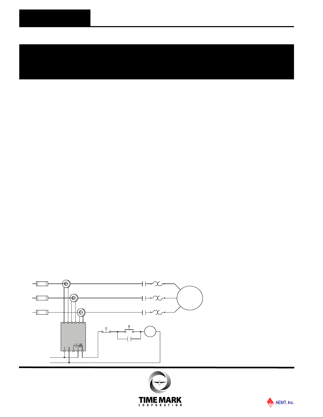
If the current to be monitored is greater than 5 amps:
Install a current transformer (CT) on the line. Connect the
secondary leads of the CT to the Model 274 terminals (see
TYPICAL APPLICATION - Over 5 Amps). Observe polarity.
Connect the operating supply voltage to the AC input
terminals.
Connect the load control wiring to the appropriate terminals.
For most motor control applications, use the
normallyclosed contact(s), which will open when the current is
above the desired trip level. For alarm applications, use the
normally-open contact(s).
Turn on the supply voltage. The contacts should not transfer,
and neither of the indicator lights should be lit.
ADJUSTMENT
Set the DELAY ADJUST to the required amount of delay.
If the desired current trip level is known, set the CURRENT
ADJUST to that point. A slight adjustment up or down may be
necessary to allow for tolerance inaccuracies.
Usually a trip is desired only if the current changes from the
present nominal. To calibrate for this (On Manual Reset
versions, press and hold the reset button during this step),
turn the DELAY ADJUST to maximum. Turn the CURRENT
ADJUST up (or down) until the OVER CURRENT indicator
lights. Turn the adjustment back until the light just goes out .
Reset the time delay to the previous setting.
TROUBLESHOOTING
Should the Model 274 3-Phase Current Monitor fail to
operate, check all connections. Verify that all three voltages
are present, and check all fuses. Should problems persist,
contact the factory at 800-862-2875, for assistance.
WARRANTY
This product is warranted to be free from defects in materials
and workmanship for one year. Should this device fail to operate, we will repair it for one year from the date of manufacture.
For complete warranty details, see the Terms and Conditions
of Sales page in the front section of the Time Mark catalog or
contact Time Mark at 1-800-862-2875.
TYPICAL APPLICATION - Over 5 Amps
Shown With No Power Applied
11/2011
© 2011 TIME MARK CORPORATION
 Loading...