

Page 1
MODEL 27
TIME MARK is a division o f
True RMS Current
Monitor
User selectable relay operation
options
Low or High Trip with independent
delays or disabled
User programmable
Can be restored to factory settings
or calibrated using a True RMS
Multimeter in the field
Model 27SG has silver with gold
flash contacts for low current.
DESCRIPTION
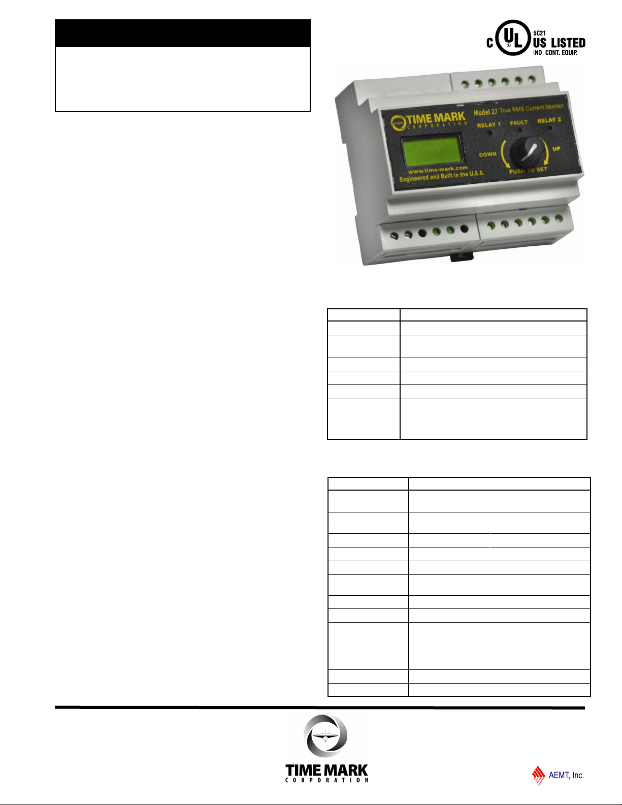
Model 27 True RMS Current Monitor has a display
that shows the current with an accuracy of +/- 0.5%.
The display is updated every second and re-initialized
every 30 seconds.
This unit has a user selectable relay option for High-Low
or DPDT. It can also be user-selected to energize on
fault or de-energize on fault. The user can select
automatic or manual restart on the Model 27. The SG
version of the Model 27 has silver with gold flash
contacts for low current applications.
Model 27 True RMS Current Monitor can be either
calibrated using a True RMS Multimeter or can be
restored to factory defaults in the field.
UL SPECIFICATIONS*
Model 27 and 27SG
Input
AC Current
Range
Amps 5A
Frequency 50/60Hz (400Hz optional with jumper)
DC Power 24 Volts, 2 watts
Output
0.5A - 1200A with External CT
0.5A - 5A at Terminals
240V AC, 10A, Resistive
120V AC, 4A, General Use
240V AC, 2A, General Use
C300, Pilot Duty
OTHER SPECIFICATIONS
Model 27 and 27SG
Max Voltage on
Current Terminals
Start-up Delay 5 secs. Min. or Automatic reset delay setting
Output Contacts SPDT x 2 10 Amps @ 240VAC
Repeat Accuracy
Reset Type
Expected Relay Life Mech: 10 million operations
Elec: 100,000 min. at rated load
Operating Temp
Humidity Tolerance
Enclosure Material
Mounting
Weight
(to allow for solid lock)
± 0.5 % (fixed conditions)
0-97% w/o condensation
600V
Manual or Automatic
-20°F to +130°F
Lexan 920
Polycarbonate
UL 94 V-0 1.5 mm
UL E45329
DIN Rail 35mm
8.5 oz.
Page 1 of 4 07/2013
© 2013 TIME MARK CORPORATION
Page 2
TIME MARK is a division o f
MODEL 27
True RMS Current Monitor
READ ALL INSTRUCTIONS BEFORE INSTALLING, OPERATING OR SERVICING THIS DEVICE.
KEEP THIS DATA SHEET FOR FUTURE REFERENCE.
GENERAL SAFETY
POTENTIALLY HAZARDOUS VOLTAGES ARE PRESENT AT THE TERMINALS OF THE MODEL 27.
ALL ELECTRICAL POWER SHOULD BE REMOVED WHEN CONNECTING OR DISCONNECTING WIRING.
THIS DEVICE SHOULD BE INSTALLED AND SERVICED BY QUALIFIED PERSONNEL.
Installation Instructions
INSTALLATION AND SETUP
Controls:
Rotary encoder with switch. Pressing the encoder
switch will display the set points. Pressing the
encoder switch for more than 5 seconds will enter
the setup mode. Pressing switch displays the next
menu item. Holding down the switch during setup
mode will sequence through menus with 1 second
intervals. Rotating the knob clockwise increases
the value and counter-clockwise will decrease
value.
For non-value options, rotating the knob either way
will change the options on the display.
Setup Options: (Press encoder for at least 5
seconds to enter setup)
High current: (Factory Enabled: Set Point = 5A,
5S Delay)
Enable/Disable: (If disabled, set point and delay
are skipped)
Set Range: Low Set + 1% to 1200A in 0.5A steps
High trip delay: 0 to 20.0 seconds in 0.1Sec
steps
Low current: (Factory Enabled: Set Point = 1A,
5S Delay)
Enable/Disable (If disabled set point and delay
are skipped)
Set Range: 1A to High Set -1% in 0.5A steps
Low trip delay: 0 to 20.0 seconds in 0.1Sec steps
Relay operation: (Factory = HI-LO)
Current High/Low option:
Separate High/Low relays
DPDT
Other faults DPDT
Relay operation on fault:
De-energize on fault
Energize on fault
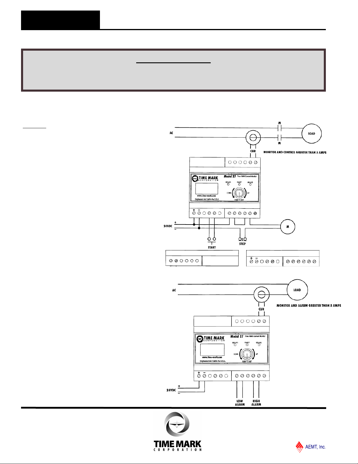
TYPICAL APPLICATION—MONITOR AND CONTROL > 5A
A/C
CURRENT
24VDC MANUAL
RESET
LOW HIGH
NO C NC | NO C NC
TYPICAL APPLICATION—MONITOR AND ALARMS > 5A
Page 2 of 4 07/2013
© 2013 TIME MARK CORPORATION
Page 3
TIME MARK is a division o f
MODEL 27
True RMS Current Monitor
READ ALL INSTRUCTIONS BEFORE INSTALLING, OPERATING OR SERVICING THIS DEVICE.
KEEP THIS DATA SHEET FOR FUTURE REFERENCE.
GENERAL SAFETY
POTENTIALLY HAZARDOUS VOLTAGES ARE PRESENT AT THE TERMINALS OF THE MODEL 27.
ALL ELECTRICAL POWER SHOULD BE REMOVED WHEN CONNECTING OR DISCONNECTING WIRING.
THIS DEVICE SHOULD BE INSTALLED AND SERVICED BY QUALIFIED PERSONNEL.
Installation Instructions
INSTALLATION AND SETUP (Continued)
High/Low Hysteresis range: (Factory Enabled: Set
Point = 5%)
As a % of set point 1 to 15% in 1% increments
HSP=High Set Point, LSP=Low Set Point,
Hy=Hysteresis
High trip:
Unit will trip at HSP and recover at HSP-
(Hy*HSP).
Low trip:
Unit will trip at LSP and recover at LSP+
(Hy*LSP).
External CT ratio (Default = 5:5)
5:5 to 1200:5
Start-up delay: (Default = 6S)
2 to 15 seconds
The device will set the relays to the normal state for
the start-up time. After the start-up time, if the
current is in the normal range, the relays will stay
in the normal state. If the current is not within the
normal range, the relays will be set to the fault
state
Restart: (Default = Automatic)
Automatic or Manual
Automatic – After a high or low fault, the device will
start the restart timer. When the timer times out,
the unit will perform a restart.
Manual - Closing an external switch will reset the
unit
If Manual, High restart and restart delay are
skipped.
High or No High Restart when Automatic: (Default =
High Restart)
High Restart – Device will restart after a high trip.
No High Restart – Device will not start after a high
trip but will restart after low trip.
Automatic Restart Delay range: (Default = 6 Mins)
1 to 300 Minutes in 1 Minute steps
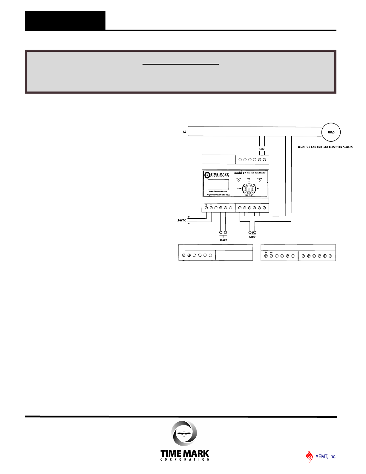
TYPICAL APPLICATION—MONITOR AND CONTROL < 5A
A/C
CURRENT
24VDC MANUAL
RESET
LOW HIGH
NO C NC | NO C NC
INSTALLATION AND SETUP (Continued)
Exit from Setup options
Repeat Setup
Press encoder to begin setup from beginning.
(High Enable)
Exit & No Save
Press encoder to exit setup. Any changes are
discarded.
Exit & Save
Press encoder to exit setup and save changes. Unit will
begin using new settings.
Start up delay:
5 Seconds Minimum (To allow for solid lock) or Start up
Delay setting. Relays will remain energized during start
up delay.
Unit can be re-calibrated in field with a Digital Multimeter
(True RMS preferred)
Factory settings can be restored in field.
Page 3 of 4 07/2013
© 2013 TIME MARK CORPORATION
Page 4
TIME MARK is a division o f
MODEL 27
True RMS Current Monitor
READ ALL INSTRUCTIONS BEFORE INSTALLING, OPERATING OR SERVICING THIS DEVICE.
KEEP THIS DATA SHEET FOR FUTURE REFERENCE.
GENERAL SAFETY
POTENTIALLY HAZARDOUS VOLTAGES ARE PRESENT AT THE TERMINALS OF THE MODEL 27.
ALL ELECTRICAL POWER SHOULD BE REMOVED WHEN CONNECTING OR DISCONNECTING WIRING.
THIS DEVICE SHOULD BE INSTALLED AND SERVICED BY QUALIFIED PERSONNEL.
Installation Instructions
MODIFYING DISPLAYED CURRENT
If measured amperage is different than the Model 27’s
displayed current, follow this procedure:
1) Measure the actual current
2) Check the secondary current of the CT with a clampon type of Ammeter
3) If the ratio is different from the theoretical current that
should be available from the CT, you can change the
CT ratio on the Model 27 to display the true reading of
the current.
OPTIONAL 400HZ FREQUENCY SETUP
To change the Model 27 from the factory default 50/60Hz
frequency to 400Hz, simply remove the blank cover plate
(without holes) and move the jumper from 50/60Hz to
400Hz . Replace the cover plate when completed.
UNIT FIELD RESTORE FACTORY SETTINGS
AND RECALIBRATION
1) From a powered down condition. Place a current
meter in series with the test current. Apply the current
to the unit first.
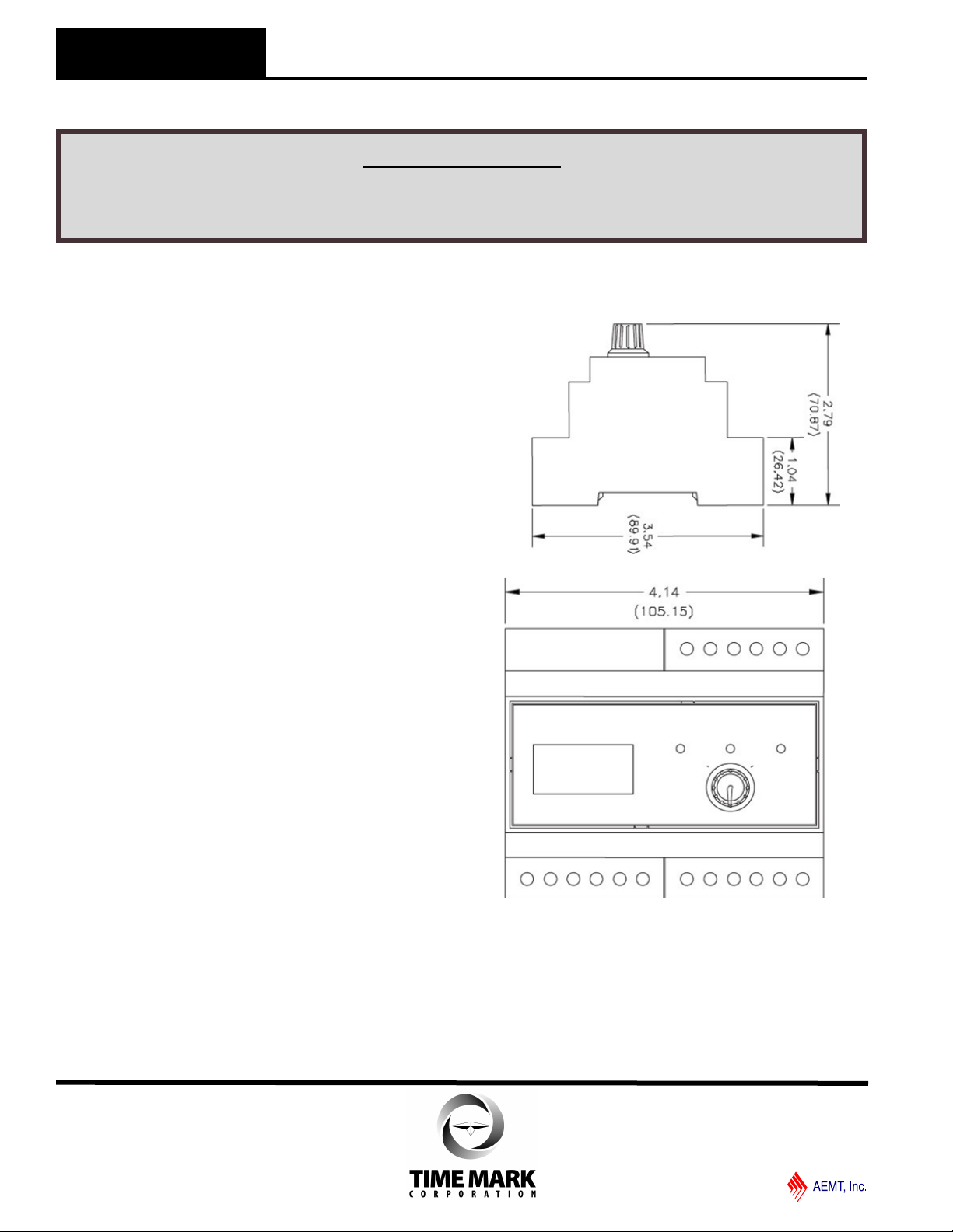
DIMENSIONS
2) Press and hold the Encoder switch while applying the
DC power to the unit. As soon as the splash screen
appears release the button. The display will show “No
Rest Fac”. Rotate encoder to change option to “Yes”
to restore factory settings. Press the Encoder switch.
3) The display will show the phase Current. Rotate
encoder to change the reading on the display to be
what is on the meter. When readings match press the
Encoder switch.
4) The unit will return to normal operation.
WARRANTY
This product is warranted to be free from defects in materials and workmanship for one year. Should this device fail to operate, we will repair it for one year from the
date of manufacture. For complete warranty details,
see the Terms and Conditions of Sales page in the front
section of the Time Mark catalog or contact Time Mark
at 1-800-862-2875.
Page 4 of 4 07/2013
© 2013 TIME MARK CORPORATION
 Loading...