

Time Mark 269R Data Sheet
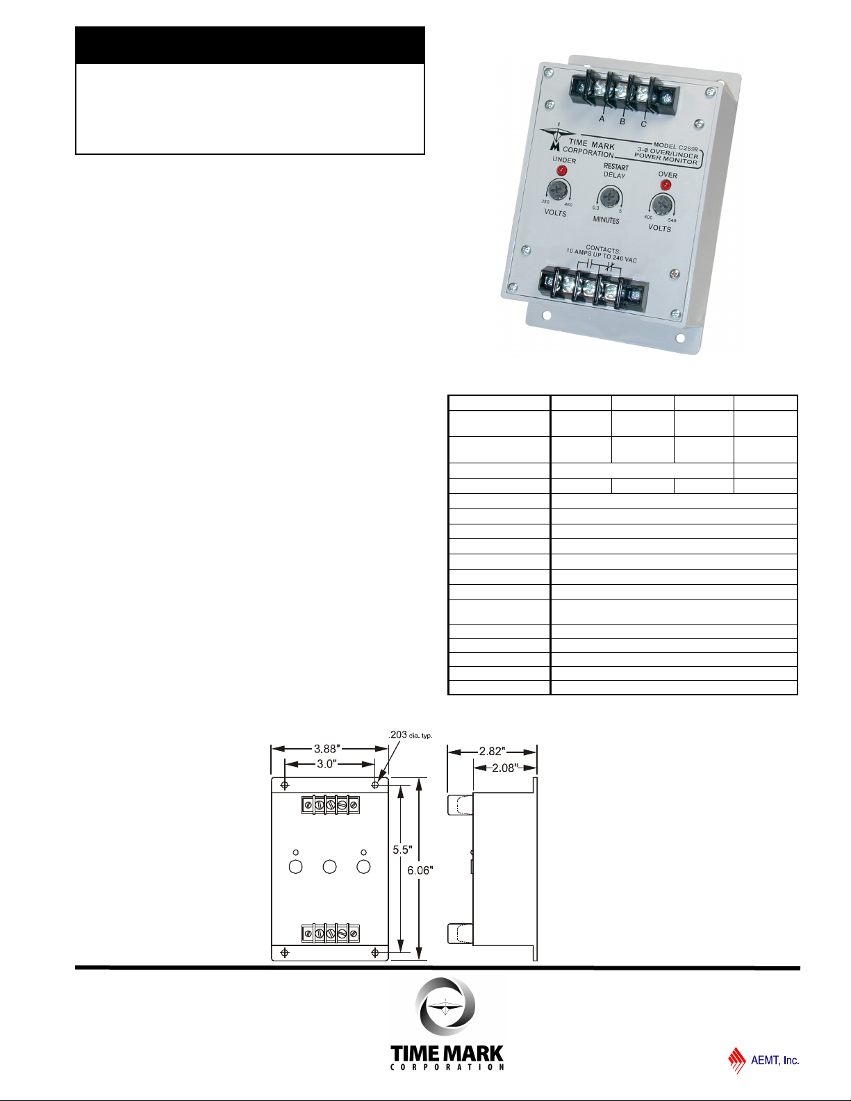
MODEL 269R
TIME MARK is a division of
Over & Under
3-Phase Monitor
Monitors for High Voltage, Low Voltage,
Phase Loss & Phase Reversal
4 Voltage Ranges
Automatic Reset
5 Year Unconditional Warranty
Adjustable Restart Delay
DESCRIPTION
The Model 269R Over & Under 3-Phase Monitor
continuously monitors 3-phase lines for high voltage, low
voltage, phase loss or phase reversal. This device
features a solid-state voltage and phase angle sensing
circuit, which drives a SPDT output relay.
The Model 269R is independent of the system load, and
may be used on any horsepower motor. When phase
sequence is correct, and the voltage remains between the
upper and lower trip points, the output relay remains
energized. When a fault condition is sensed, the output
relay drops out.
The Model 269R does not require a neutral connection,
and can be used on Wye or Delta systems. Each of the
four voltage versions can be adjusted over a wide range.
An adjustable restart delay (0.3-5 minutes) allows
compressor head pressures to bleed off, in the event of
short-term power failures. OVER and UNDER voltage
failure indicators aid in calibration and system
troubleshooting.
DIMENSIONS
SPECIFICATIONS
Model A269R B269R C269R EX269R
Nominal AC Voltage
(phase to phase)
Adj Range - Upper
- Lower
Frequency 60Hz 50Hz
Power Consumption
Transient Protection 2500VRMS for 10ms
Repeat Accuracy
Response Time 4 ±2 seconds fixed
Reset Time Adjustable 0.3 to 5 minutes
Reset Type Automatic
Dead Band Approximately 2%
Output Contacts SPDT 10A at 240VAC resistive
Expected Relay Life Mech: 10 million operations
Operating Temp - 20º to +130º F
Humidity Tolerance 0-97% w/o condensation
Enclosure Material ABS Plastic
Mounting Surface
Weight 9 oz.
120VAC 208/240VAC 480VAC 380VAC
110 - 145V
80 - 115V
1.5W
Elec: 100,000 operations at rated load
210 - 280V
170 - 240V
3W 6W 6W
± 0.1% of set point (fixed conditions)
400 - 540V
380 - 460V
350 - 450V
300 - 400V
11/2011
© 2011 TIME MARK CORPORATION
MODEL 269R
TIME MARK is a division of
Over & Under 3-Phase Monitor
READ ALL INSTRUCTIONS BEFORE INSTALLING, OPERATING OR SERVICING THIS DEVICE.
KEEP THIS DATA SHEET FOR FUTURE REFERENCE.
GENERAL SAFETY
POTENTIALLY HAZARDOUS VOLTAGES ARE PRESENT AT THE TERMINALS OF THE MODEL 269R .
ALL ELECTRICAL POWER SHOULD BE REMOVED WHEN CONNECTING OR DISCONNECTING WIRING.
THIS DEVICE SHOULD BE INSTALLED AND SERVICED BY QUALIFIED PERSONNEL.
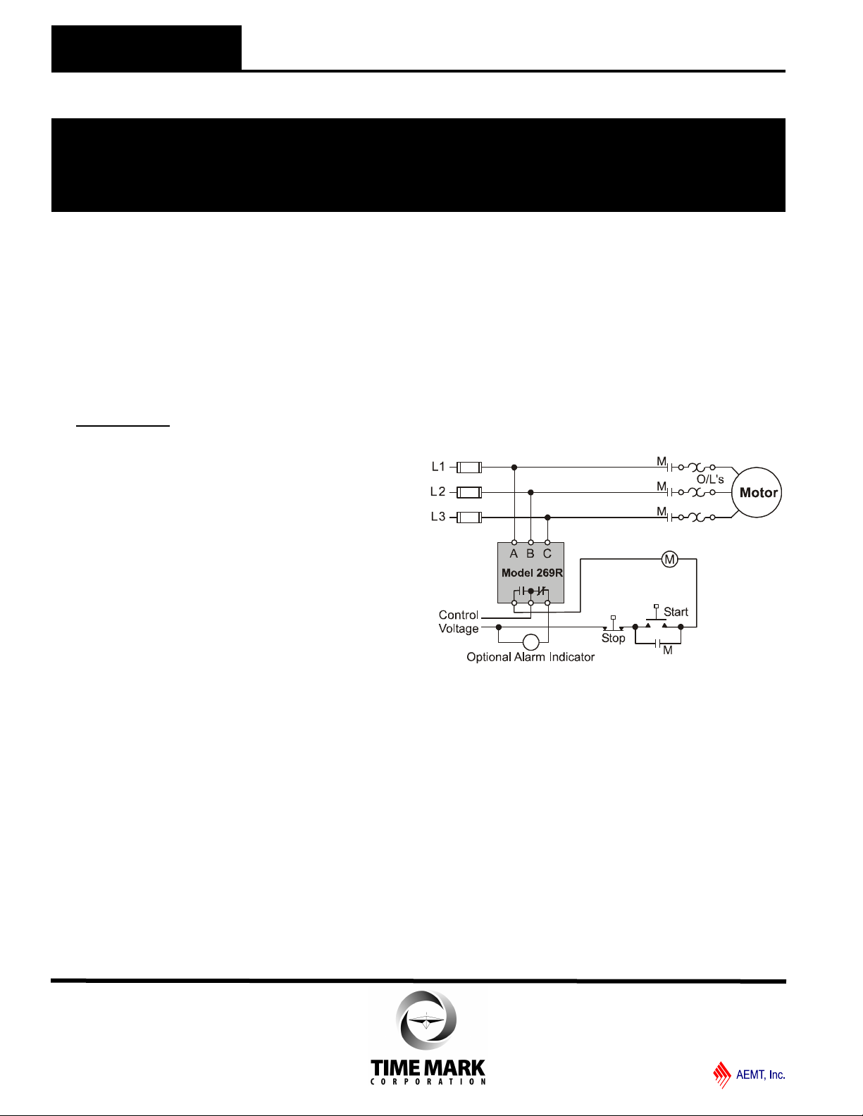
Installation Instructions
INSTALLATION
Rotate both the UNDER VOLTS and MINUTES
adjustments counter-clockwise, and OVER VOLTS adjustment clockwise. The 3-phase wiring should be
connected to the terminals marked A, B and C.
The control wiring will be connected to the opposite end
of the unit, to the terminals with the relay contact
markings. The markings printed on the Model 269R are
the failed condition of the contacts.
When power is applied to the unit, the TRIP LED
indicator should not be lit (the reset switch may have to
be pressed on manual reset versions). If the TRIP
indicator comes on when power is applied, check that
all three phases are present and of the correct voltage.
If the voltage is correct, remove power, then reverse
two of the three phase wires.
Re-apply power. The TRIP indicator should not be on.
After a brief delay (approx. 20 seconds) the contacts
will transfer.
ADJUSTMENT SETTINGS
Rotate the UNDER VOLTS adjustment clockwise, until
the contacts trip and the UNDER indicator illuminates.
Slowly rotate the UNDER VOLTS adjustment counterclockwise, until the LED goes out (on manual reset versions, hold the RESET button down while making this
adjustment). Rotate the OVER VOLTS adjustment
counter-clockwise, until the contacts trip and the OVER
trip indicator illuminates. Slowly rotate the OVER
VOLTS adjustment clockwise until the LED goes out.
After approximately 20 seconds, the contacts will
transfer and the NORMAL indicator will come on. If
nuisance trips occur, rotate the VOLTS adjustment
slightly farther, counter-clockwise. This method of
adjustment will be correct in most cases.
Set the MINUTES delay as required. Application
dependent.
TROUBLESHOOTING
Should the Model 269R Monitor fail to operate properly,
check that all three voltages are present, and are of the
correct voltage level and phase rotation (a Model 108A
or 108B Phase Sequence Detector should be used to
verify phase rotation). Check all fuses and verify that all
wiring connections are correct. If problems persist,
contact your local Time Mark Distributor, or the factory
for assistance.
TYPICAL APPLICATION
Shows No Power Applied
WARRANTY
This product is warranted to be free from defects in
materials and workmanship, and is covered by our
exclusive 5-year Unconditional Warranty. Should this
device fail to operate for any reason, we will repair it for
five years from the date of manufacture. For complete
warranty details, see the Terms and Conditions of Sales
page in the front section of the Time Mark catalog or
contact Time Mark at 1-800-862-2875.
11/2011
© 2011 TIME MARK CORPORATION
 Loading...