

Page 1
MODEL 2642
TIME MARK is a division of
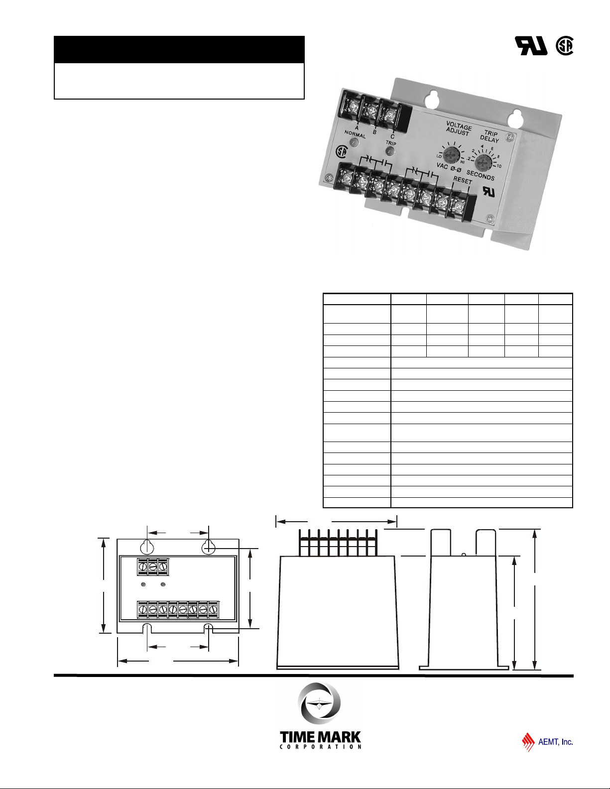
4.5"
4.8"
4.0"
4.5"
3.5"
2.25"
2.25"
3.13"
3-Phase Monitor
Detects Phase Loss, Low Voltage
and Phase Reversal
Adjustable Trip Delay
Automatic or Manual Reset
DPDT Output Contacts
DESCRIPTION
The Model 2642 3-Phase Monitor protects electrical
equipment by sensing phase loss, low voltage and reverse
phase conditions. This device uses a combination of
voltage and phase angle sensing, and will detect a phase
loss even when regenerated voltages are present.
The Model 2642 is fail-safe; the output contacts will
transfer when correct power is applied, and trip out on any
fault condition or complete loss of power. Each of five
voltage versions can be adjusted throughout a wide
operating range. An adjustable trip delay timer prevents
nuisance tripping caused by momentary voltage dips.
The DPDT output contacts allow the Model 2642 to be
used in control circuits and alarm circuits. The automatic reset can be converted to a manual reset by
adding a normally closed switch.
DIMENSIONS
SPECIFICATIONS
MODEL A2642 B2642 C2642 D2642 EX2642
Nominal AC Voltage
(phase to phase)
Adjustment Range 85-125V 160-260V 380-500V 450-600V 300-400V
Frequency 60Hz 60Hz 60Hz 60Hz 50Hz
Power Consumption
Transient Protection 2500 VRMS for 10ms
Repeat Accuracy
Response Time
Reset Time
Dead Band Approximately 2%
Output Contacts DPDT 10 amps at 240VAC resistive
Expected Relay Life Mech: 10 million operations
Operating Temp - 20° to +131° F
Humidity Tolerance 0 - 97% w/o condensation
Enclosure Material ABS plastic
Mounting Surface
Weight 12 oz.
Agency Approvals UL Recognized; CSA Certified
120VAC 208/240VAC 480VAC 575VAC 380VAC
0.25W 0.5W 1.5W 2.5W
Elec: 100,000 operations at rated load
1.5W
± 0.5% of setpoint (fixed conditions)
Adjustable 0.2 to 10 seconds ±5%
0.15 seconds
11/2011
© 2011 TIME MARK CORPORATION
Page 2
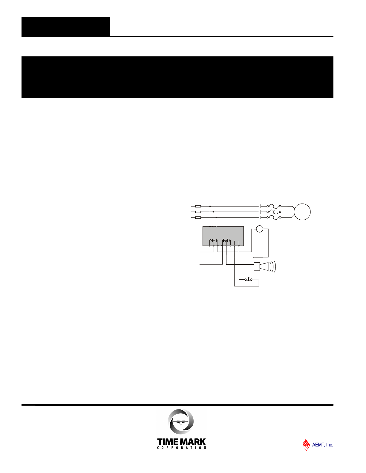
Alarm (optional)
M
M
Motor
M
L1
L2
L3
Control
Voltage
Alarm
Circuit
O/L
M
A BC
Model 2642
RESET
Manual Reset (omit for auto reset)
Shown with no power applied
MODEL 2642
TIME MARK is a division of
3-Phase Monitor
READ ALL INSTRUCTIONS BEFORE INSTALLING, OPERATING OR SERVICING THIS DEVICE.
KEEP THIS DATA SHEET FOR FUTURE REFERENCE.
GENERAL SAFETY
POTENTIALLY HAZARDOUS VOLTAGES ARE PRESENT AT THE TERMINALS OF THE MODEL 2642.
ALL ELECTRICAL POWER SHOULD BE REMOVED WHEN CONNECTING OR DISCONNECTING WIRING.
THIS DEVICE SHOULD BE INSTALLED AND SERVICED BY QUALIFIED PERSONNEL.
Installation Instructions
INSTALLATION
Turn both adjustment control potentiometers fully counterclockwise.
Connect the 3-phase wires to the terminals marked A, B
and C.
Connect the control wires to one set of the terminals with
the relay contact markings. The contact markings on the
unit are the failed or tripped condition of the contacts. The
second set of output terminals can be used in an alarm
circuit or in the control circuit of a second load. Refer to
the TYPICAL APPLICATION drawing.
As provided, the Model 2642 has an Automatic Reset. If
you prefer a Manual Reset, install a normally-closed push
button across the terminals marked RESET. The Manual
Reset leads should be kept as short as possible.
Apply power. If the contacts do not transfer when power is
applied (TRIPPED indicator off; NORMAL indicator on),
check that all three phases are present and of the correct
voltage.
If all phases are correct, remove power from the unit,
reverse any two of the A, B or C terminal wires (phase
rotation is reversed), and re-apply power. The contacts
should then transfer.
ADJUSTMENT
NOTE: When adjusting the Model 2642 you may wish to
jumper the control circuit contacts (& disconnect the alarm
contacts, if used) to prevent the unit from cycling the load.
Rotate the VOLTAGE ADJUST pot clock-wise until the unit
trips (NORMAL indicator off, TRIP indicator on).
Slowly turn the VOLTAGE ADJUST pot counter-clockwise
until the unit resets (TRIP indicator off; NORMAL indicator
on).
Set the TRIP DELAY adjustment to the desired amount of
delay to prevent nuisance trips.
These adjustment settings will be correct for most
applications. Should nuisance trips occur, even with the
TRIP DELAY set, turn the VOLTAGE ADJUST pot slightly
farther counter-clockwise. Any adjustments should be
made in very small increments.
TYPICAL APPLICATION
Shows No Power Applied
WARRANTY
This product is warranted to be free from defects in
materials and workmanship, and is covered by our
exclusive 5-year Unconditional Warranty. Should this
device fail to operate for any reason, we will repair it for
five years from the date of manufacture. For complete
warranty details, see the Terms and Conditions of Sales
page in the front section of the Time Mark catalog or
contact Time Mark at 1-800-862-2875.
11/2011
© 2011 TIME MARK CORPORATION
 Loading...