

Page 1
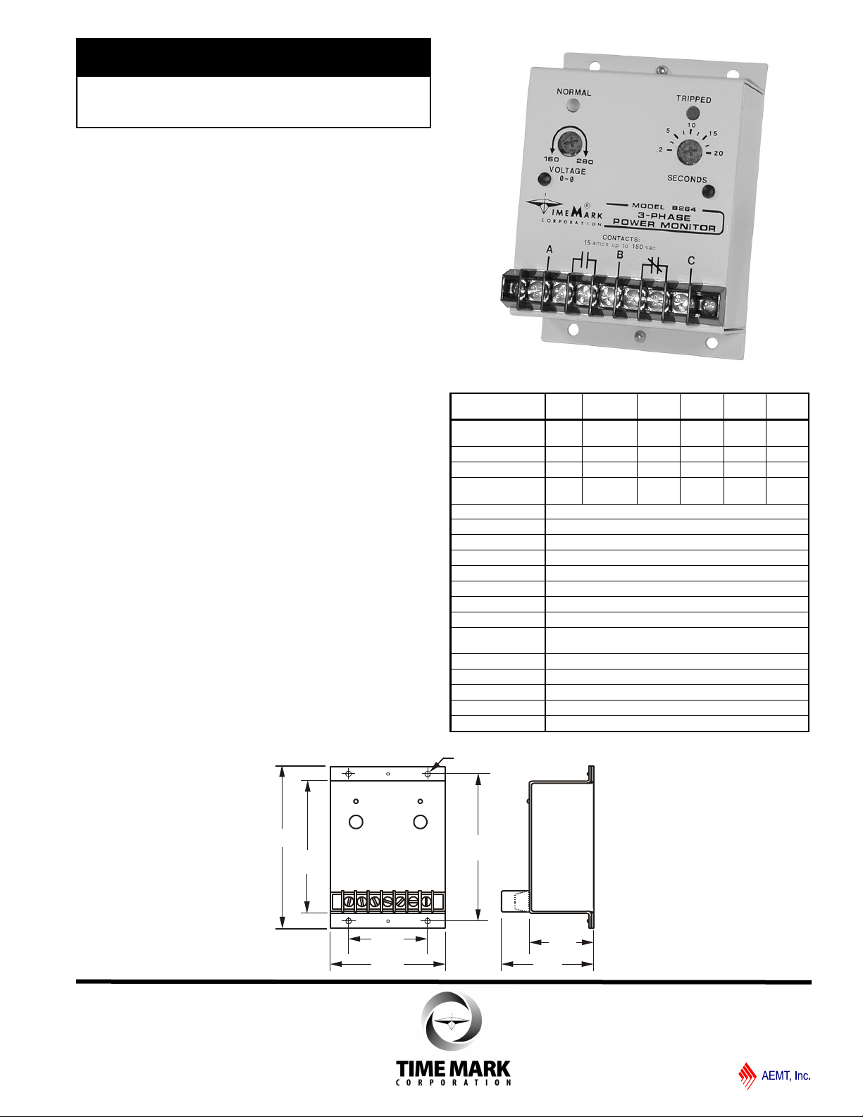
4.31"
4.75"
3.87"
2.31"
3.38"
1.88"
2.70"
.19 dia. typ.
MODEL 264
TIME MARK is a division of
3-Phase Monitor
Detects Phase Loss, Low Voltage,
Phase Reversal
Adjustable Trip Delay
Isolated Contacts
5 Year Unconditional Warranty
DESCRIPTION
The Model 264 3-Phase Monitor continuously monitors
3-phase Wye or Delta systems for abnormal conditions.
The solid-state electronic sensing circuit drives two
separate SPST relays, one normally open and the other
normally closed. An adjustable trip delay reduces or
eliminates nuisance tripping caused by momentary
voltage fluctuations on motor start-up.
Standard versions are 120V, 208/240V, 480V and 575V
at 60Hz; and 380V or 415V at 50Hz. Voltage ranges are
sufficiently wide to allow for proper adjustment to
existing conditions. Both TRIPPED and NORMAL indicators are provided to aid in trip point adjustments and
system troubleshooting.
The Model 264 is not sensitive to line current and can
be used with any size motor or compressor.
DIMENSIONS
SPECIFICATIONS
Model A264 B264 C264 D264 EX264-
Nominal AC Voltage
(phase to phase)
Adjustment Range
Frequency
Power Consumption
(per phase)
Transient Protection 2500VAC for 10ms
Repeat Accuracy
Response Time 2 +/- 2 to 20 +10/-2 seconds
Reset Time
Reset Type Automatic
Dead Band Approximately 8% of 125VAC or 10VAC
Output Contacts One (1) SPST N.O. One (1) SPST N.C.
Contact Rating 10 amps at 240VAC resistive
Expected Relay Life Mech: 10 million operations
Operating Temp - 20° to +130° F
Humidity Tolerance 0 - 97% w/o condensation
Enclosure Material 20 gauge steel
Mounting Surface
Weight 10 oz.
120VAC 208/240VAC 480VAC 575VAC 380VAC 415VAC
85-125V 160-260V 380-500V 450-600V 300-400V 340-460V
60Hz 60Hz 60Hz 60Hz 50Hz 50Hz
0.25W 0.5W 1.5W 2.5W 1.5W 1.5W
± 0.1% of set point (fixed conditions)
0.15 seconds
Elec: 100,000 operations at rated load
380
EX264415
11/2011
© 2011 TIME MARK CORPORATION
Page 2
MODEL 264
A B C
START
STOP
ALARM
M
M
M
M
MOTOR
M
L1
L2
L3
MODEL
264
CONTROL
CIRCUIT
ALARM
CIRCUIT
O/L's
TIME MARK is a division of
3-Phase Monitor
READ ALL INSTRUCTIONS BEFORE INSTALLING, OPERATING OR SERVICING THIS DEVICE.
KEEP THIS DATA SHEET FOR FUTURE REFERENCE.
GENERAL SAFETY
POTENTIALLY HAZARDOUS VOLTAGES ARE PRESENT AT THE TERMINALS OF THE MODEL 264.
ALL ELECTRICAL POWER SHOULD BE REMOVED WHEN CONNECTING OR DISCONNECTING WIRING.
THIS DEVICE SHOULD BE INSTALLED AND SERVICED BY QUALIFIED PERSONNEL.
Installation Instructions
WARNING
The Model 264 is not to be used in applications
where voltages to be monitored or switched
will exceed voltage specifications for the
particular unit. See ‘Adjustment Range’ in the
Specifications table on the reverse side of this
data sheet.
INSTALLATION
Connect the 3-phase wires to the terminals marked A, B
and C. Turn both controls fully counter-clockwise.
Connect the control wires to the terminals with the relay
contact markings. NOTE: The contact markings on the
unit are the TRIPPED condition of the contacts.
Apply power. If the contacts do not transfer when power is
applied (NORMAL indicator on), check that all three
phases are present, and of the correct voltage. If all
phases are correct, rotate the VOLTAGE adjustment
counter-clockwise, to the low position. If the contacts still
do not transfer, remove power from the unit. Reverse any
two of the three input wires, and re-apply power. The
contacts should transfer to the normal condition (normallyopen contact closed, NORMAL indicator ON).
ADJUSTMENT
NOTE: During adjustment, you may want to install a
jumper across the control contacts, to prevent cycling the
load on and off.
Set the trip delay to .2 seconds.
Rotate the VOLTAGE adjustment slowly clockwise until the
contacts transfer to the failed condition (TRIPPED indicator
lit).
Slowly turn the VOLTAGE adjustment counter-clockwise,
until the contacts reset to the normal condition (NORMAL
indicator on).
If you installed a jumper across the control contacts to
prevent load cycling, remove it now.
Set the SECONDS adjustment to the desired amount of
trip delay. ThIs trip delay will prevent most nuisance
tripping; however, if nuisance tripping does occur, turn the
VOLTAGE adjustment slightly farther, counter-clockwise.
In making adjustments to eliminate nuisance tripping,
the VOLTAGE adjustment should be rotated in very
small increments, until the true nuisance trips are
eliminated.
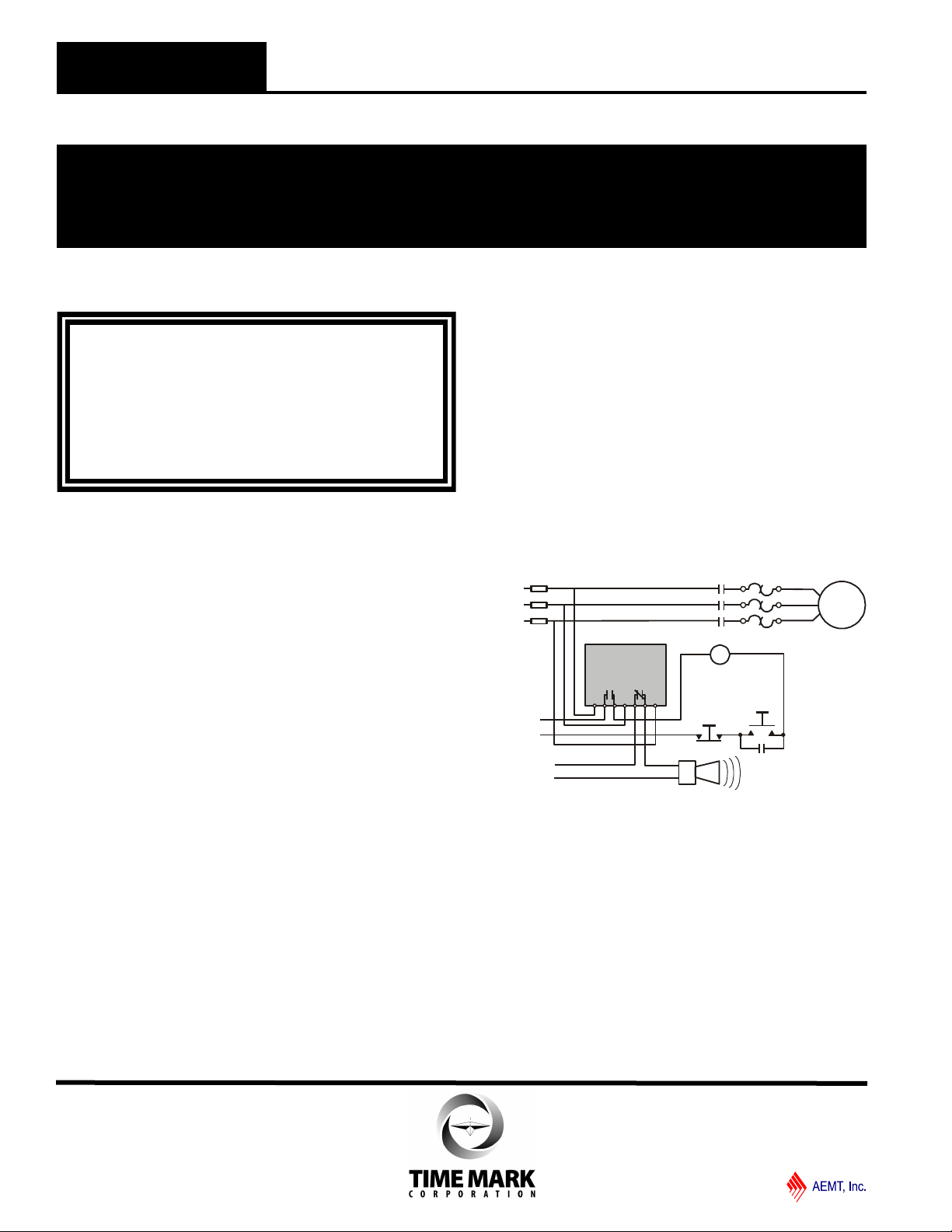
TYPICAL APPLICATION
Shown De-Energized
WARRANTY
This product is warranted to be free from defects in
materials and workmanship, and is covered by our
exclusive 5-year Unconditional Warranty. Should this
device fail to operate for any reason, we will repair it for
five years from the date of manufacture. For complete
warranty details, see the Terms and Conditions of Sales
page in the front section of the Time Mark catalog or
contact Time Mark at 1-800-862-2875.
11/2011
© 2011 TIME MARK CORPORATION
 Loading...