

Page 1
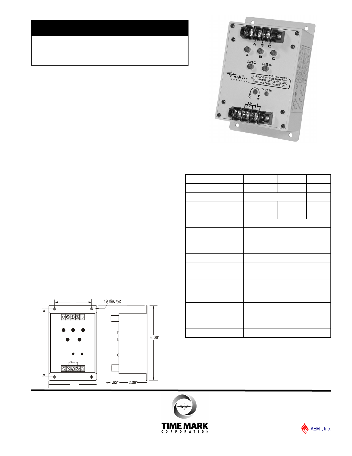
MODEL 2638
TIME MARK is a division of
3.0"
5.5"
3.88"
ABC
3-Phase Monitor
with Line Voltage & Phase Sequence Indicator
Detects Phase Loss, Phase Reversal
and Low Voltage
LED Status Indicators
Automatic Reset
5 Year Unconditional Warranty
DESCRIPTION
The Model 2638 3-Phase Monitor combines a 3-phase
monitor with a line voltage and phase sequence indicator.
Like other Time Mark monitors, the Model 2638 senses
phase loss, phase reversal and low voltage.
When power and phasing are correct, the internal relay
energizes. Status indicators will show that all phases are
present, and the direction of phase rotation.
When a fault occurs, the monitor trips its relay and
indicates which phase is lost, or, if a reversal is present.
This allows you to automatically protect your equipment by
correcting for the appropriate fault condition. The Model
2638 will automatically reset when correct power is
restored.
One 50Hz version and two 60Hz versions are available
from stock.
DIMENSIONS
SPECIFICATIONS
Model B2638 C2638 EX2638
Nominal Voltage 208/240VAC 480VAC 380VAC
Frequency 60Hz 50Hz
Adjustment Range 160-240 380-480 300-400
Power Consumption 3.7W 6.7W 6.5W
Transient Protection 2500V for 10ms
Repeat Accuracy ±0.1% (fixed conditions)
Response Time 0.05 seconds
Reset Time 0.05 seconds
Reset Type Automatic
Dead Band Approximately 2%
Output Contacts SPDT 10A at 240VAC resistive
Expected Relay Life Mech: 10 million operations
Elec: 100,000 operations at rated load
Operating Temperature -20° to +131° F
Humidity Tolerance 0-97% w/o condensation
Enclosure Material ABS plastic
Mounting Surface
Weight 12 oz.
11/2011
© 2011 TIME MARK CORPORATION
Page 2
OPTIONAL
ALARM
INDICATOR
STOP
START
MODEL
2638
O/L's
MODEL 2638
TIME MARK is a division of
3-Phase Monitor
READ ALL INSTRUCTIONS BEFORE INSTALLING, OPERATING OR SERVICING THIS DEVICE.
KEEP THIS DATA SHEET FOR FUTURE REFERENCE.
GENERAL SAFETY
POTENTIALLY HAZARDOUS VOLTAGES ARE PRESENT AT THE TERMINALS OF THE MODEL 2638.
ALL ELECTRICAL POWER SHOULD BE REMOVED WHEN CONNECTING OR DISCONNECTING WIRING.
THIS DEVICE SHOULD BE INSTALLED AND SERVICED BY QUALIFIED PERSONNEL.
Installation Instructions
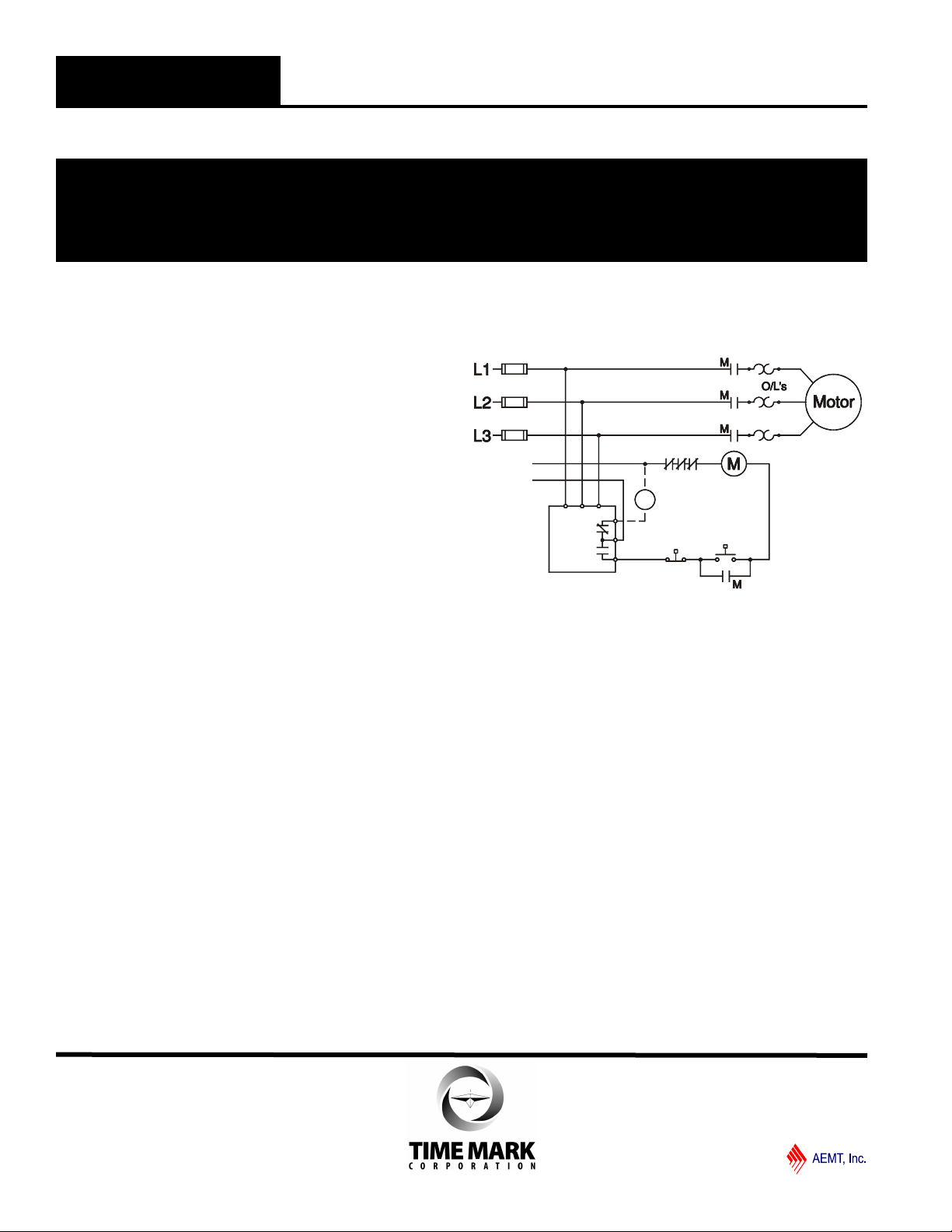
INSTALLATION
Mount the monitor in a suitable enclosure.
Connect 3-phase power to the terminals marked A, B and C.
For motor control applications, connect the load control
wiring to the normally open (NO) relay contacts.
For phase loss alarm applications, connect wiring to the
normally closed (NC) relay contacts.
Apply power. If the contacts do not transfer (TRIPPED
indicator ON), check that the three voltage indicators are lit
and that the ABC indicator is lit.
If one or more of the voltage indicators are off, not all phases
are present or of the correct voltage level.
If the CBA indicator is lit, remove power and reverse two of the
three phase wires (phase rotation is reversed).
Re-apply power. If the contacts still do not transfer, rotate the
TRIPPED level adjustment fully counter-clockwise. The
contacts should transfer, the TRIPPED indicator should be off,
the ABC indicator should be lit, and all three voltage indicators
should be lit.
ADJUSTMENT
Rotate the TRIPPED level adjustment clockwise until the relay
contact transfers (TRIPPED indicator ON). Slowly turn the
adjustment counter-clockwise, until the contacts resets.
This adjustment method sets the trip point roughly 5-10%
below the nominal voltage, and will be correct for most motor
applications. Should nuisance tripping occur, turn the
adjustment slightly farther counter-clockwise.
A more accurate adjustment method requires a 3-phase
variac, allowing the voltage to be lowered to a specific voltage
level. The 2638 can then be set to trip at this precise voltage.
If desired, the trip point can be factory pre-set for a nominal
fee. Contact the factory for more information.
TYPICAL APPLICATION
Shown De-Energized
TROUBLESHOOTING
Should the monitor fail to operate properly, check that all three
phases are present and of the correct voltage level. Check all
fuses and verify that all wiring connections are correct. Should
problems persist, contact the factory for assistance.
WARRANTY
This product is warranted to be free from defects in materials
and workmanship, and is covered by our exclusive 5-year
Unconditional Warranty. Should this device fail to operate
for any reason, we will repair it for five years from the date of
manufacture. For complete warranty details, see the Terms
and Conditions of Sales page in the front section of the Time
Mark catalog or contact Time Mark at 1-800-862-2875.
11/2011
© 2011 TIME MARK CORPORATION
 Loading...